
PS8RE III - Audio/video extension Furman - Free user manual and instructions
Find the device manual for free PS8RE III Furman in PDF.
| Product Type | Power conditioner / audio/video sequencer |
| Brand | Furman |
| Model | PS8RE III |
| Dimensions (H x W x D) | 44.33 x 482.6 x 165.1 mm |
| Weight | 3.03 kg |
| Power | 220-240 V AC, 50-60 Hz, 10 A max (thermal circuit breaker) |
| Number of outlets | 9 IEC-C13 outlets (1 front, 8 rear) including 3 switched and 6 sequenced |
| Surge protection | SMP+ (Series Multi-Stage Protection Plus) with clamp at 376 Vpeak and EVS (275 V AC) |
| Filtering | LiFT (Linear Filtering Technology): 10 dB @ 10 kHz, 40 dB @ 100 kHz, 50 dB @ 500 kHz |
| Sequencing | 3 steps with adjustable delay (0.5 to 10 seconds per step) |
| Remote control | 4-pin Phoenix interface (12 V, STAT, REM, GND) compatible with RS-1/RS-2 |
| Rear lamp | BNC connector for gooseneck lamp 12 V DC/AC, 0.5 A max |
| Indicators | LEDs: Power, Protection OK, EVS, DELAY 1/2/3 |
| Switches | Main on/off, sequence, rear lamp, resettable circuit breaker |
| Multiple connection | Ability to link multiple PS-8RE units in series or parallel |
| Maintenance | Clean with a dry cloth only |
| Safety | 10 A thermal circuit breaker, EVS protection, mandatory grounding |
| Warranty | 3 years for original purchaser (subject to conditions) |
| Operating temperature | 5 °C to 40 °C |
| Humidity | Less than 90% RH |
Frequently Asked Questions - PS8RE III Furman
User questions about PS8RE III Furman
0 question about this device. Answer the ones you know or ask your own.
Ask a new question about this device
Download the instructions for your Audio/video extension in PDF format for free! Find your manual PS8RE III - Furman and take your electronic device back in hand. On this page are published all the documents necessary for the use of your device. PS8RE III by Furman.
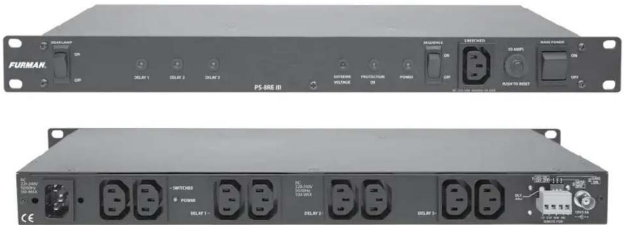
USER MANUAL PS8RE III Furman
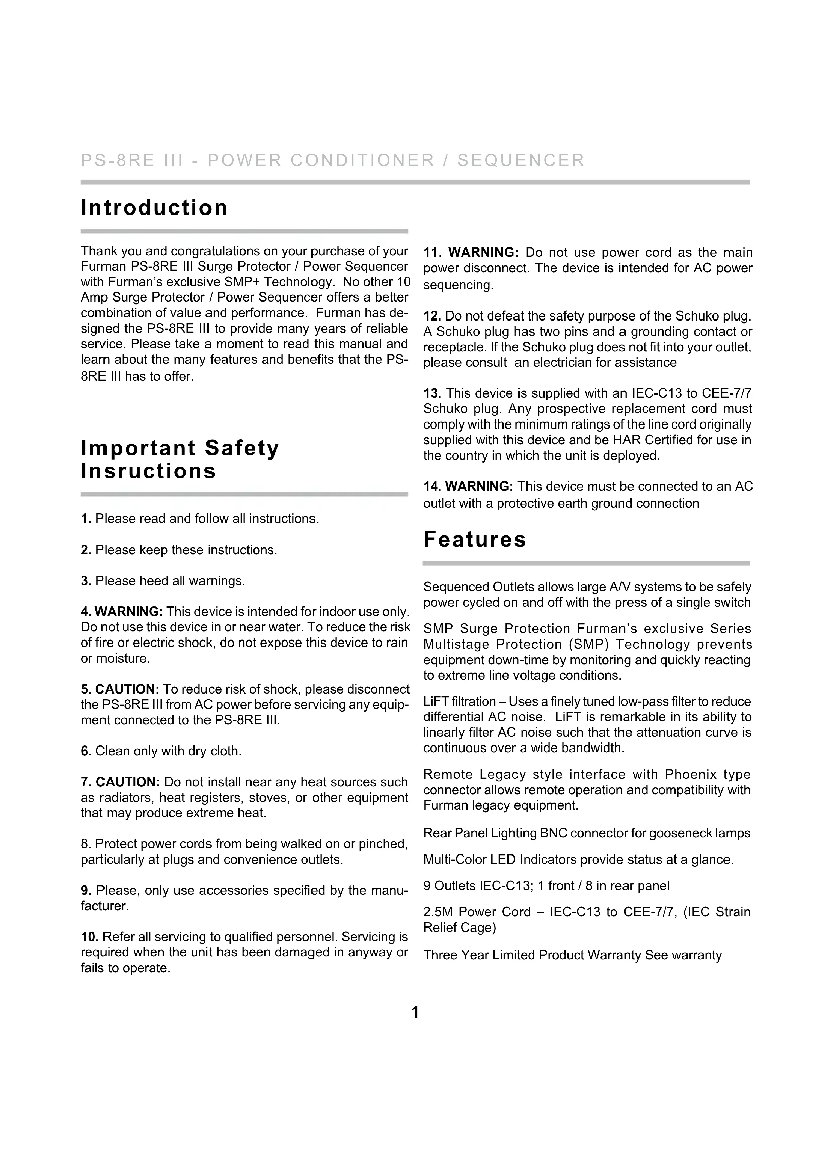
Power Conditioner / Sequencer
text_image
FURMAN. REM LAMP ON OFF DELAY 1 DELAY 2 DELAY 3 PS-BRE III EXTRAIRE VOLTAGE PROTECTION ON POWER SEQUENCE ON OFF SWITCHED 10 AMPS MAIN POWER ON PUSH TO RESET OFF AC: 220-480V DC/DVD 10A MAX CE -SWITCHES POWER DELAY 1- DELAY 2- DELAY 3- AC: 220-480V DC/DVD 10A MAX OUT: 10V/1.5A AMBI PUTEnglish 1 - 11
Deutsch 12 - 23
Français 24 - 35
Español 36 - 47
Русский 48 - 58
Introduction
Thank you and congratulations on your purchase of your Furman PS-8RE III Surge Protector / Power Sequencer with Furman's exclusive SMP+ Technology. No other 10 Amp Surge Protector / Power Sequencer offers a better combination of value and performance. Furman has designed the PS-8RE III to provide many years of reliable service. Please take a moment to read this manual and learn about the many features and benefits that the PS-8RE III has to offer.
Important Safety Instructions
-
Please read and follow all instructions.
-
Please keep these instructions.
-
Please heed all warnings.
-
WARNING: This device is intended for indoor use only. Do not use this device in or near water. To reduce the risk of fire or electric shock, do not expose this device to rain or moisture.
-
CAUTION: To reduce risk of shock, please disconnect the PS-8RE III from AC power before servicing any equipment connected to the PS-8RE III.
-
Clean only with dry cloth.
-
CAUTION: Do not install near any heat sources such as radiators, heat registers, stoves, or other equipment that may produce extreme heat.
-
Protect power cords from being walked on or pinched, particularly at plugs and convenience outlets.
-
Please, only use accessories specified by the manufacturer.
-
Refer all servicing to qualified personnel. Servicing is required when the unit has been damaged in anyway or fails to operate.
-
WARNING: Do not use power cord as the main power disconnect. The device is intended for AC power sequencing.
- Do not defeat the safety purpose of the Schuko plug. A Schuko plug has two pins and a grounding contact or receptacle. If the Schuko plug does not fit into your outlet, please consult an electrician for assistance
- This device is supplied with an IEC-C13 to CEE-7/7 Schuko plug. Any prospective replacement cord must comply with the minimum ratings of the line cord originally supplied with this device and be HAR Certified for use in the country in which the unit is deployed.
- WARNING: This device must be connected to an AC outlet with a protective earth ground connection
Features
Sequenced Outlets allows large A/V systems to be safely power cycled on and off with the press of a single switch
SMP Surge Protection Furman's exclusive Series Multistage Protection (SMP) Technology prevents equipment down-time by monitoring and quickly reacting to extreme line voltage conditions.
LiFT filtration – Uses a finely tuned low-pass filter to reduce differential AC noise. LiFT is remarkable in its ability to linearly filter AC noise such that the attenuation curve is continuous over a wide bandwidth.
Remote Legacy style interface with Phoenix type connector allows remote operation and compatibility with Furman legacy equipment.
Rear Panel Lighting BNC connector for gooseneck lamps Multi-Color LED Indicators provide status at a glance.
9 Outlets IEC-C13; 1 front / 8 in rear panel
2.5M Power Cord - IEC-C13 to CEE-7/7, (IEC Strain Relief Cage)
Three Year Limited Product Warranty See warranty
Sequenced Outlets
AV equipment is most vulnerable and susceptible to damage during those first few milliseconds after the power is turned on or off.
When audio amplifiers are powered on, a large inrush current occurs as the large capacitors in the power supply charge. This inrush can be on the order of several hundred amps for a number of AC cycles. If more than one amplifier is connected to a single branch circuit, the inrush current is multiplied and can cause the circuit breaker to trip, or the line voltage to sag. Additionally, if the amplifier is powered on either before or concurrent with signal processing equipment, the result can be a dreaded speaker "pop". This all-too familiar noise occurs as transients from the signal processing equipment flow uncontrolled to the inputs of the power amplifier. The amplifier amplifies this signal and passes the transient "pop" along to the speakers. The result can be catastrophic to both speaker and amplifier.
Powering down A/V is equally as perilous. Unlike other A/V equipment, the large capacitors found in amplifiers will store their charge. This means if signal processing devices and amplifiers are switched off simultaneously, the amplifiers are still operational as the signal processing equipment is switched off. Just as with startup, the power down phase can cause equipment to emit transients which are amplified by the amplifier, then propagated to the speakers and "pop"!
AC Power sequencing addresses these problems by powering up your equipment in stages. The signal processing equipment is powered on first and allowed to stabilize, and then the amplifiers are powered on.
The first stage signal processing equipment may still emit transient noise upon power up, but because the amplifiers have yet to power on, the transient signal passes without incident. Power sequencing stages the activation of heavy loads, which prevents nuisance breaker trips and equipment damage due to line sags and brown-outs. This means that inrush currents are offset in time, rather than occurring simultaneously. This can also be advantageous to upstream equipment if the sequencer is supplementing other power management such as a UPS or voltage regulator.
The Furman PS-8RE III provides three delay stages. If three stages of power sequencing are not enough for your application, you can chain together multiple PS-8RE III sequencers. For best results we recommend that your power amplifiers always receive power last. Plug the amplifiers into DELAY 3, or divide them into two groups and plug one group into DELAY 2, and the other into DELAY 3. The low level equipment feeding the amps, such as mixers and signal processors, should plug into DELAY 1 such that they will turn on and stabilize first.
The turn-on delay intervals are factory preset to 5 seconds per stage. This delay can be increased or decreased using the rear panel trim pot adjustment (see "Adjusting the Delay Interval" for details).
In the event of a power outage, all equipment plugged into the PS-8RE III will lose power simultaneously. When power is restored, the behavior of the PS-8RE III will depend upon switch settings and how the unit has been configured:
- If the PS-8RE III has been configured for Maintained mode and the Sequence switch is in the ON position, the delayed outlet groups will turn on in the normal delayed sequence when power is restored.
- If the PS-8RE III has been configured for Momentary mode the delay outlets will remain off until activated by the end user.
SMP+ (Series Multi-Stage Protection Plus)
Furman's SMP+ surge suppression virtually eliminates service calls. Traditional surge suppression circuits “sacrifice” themselves when exposed to multiple transient voltage spikes, requiring the dismantling of your system, and repair of your surge suppressor. With Furman's SMP+, however, damaging transient voltages are safely absorbed, clamped, and dissipated.
Unique to Furman's SMP+ is its unparalleled clamping voltage. While other designs offer clamping voltages that are well above 660 Vpeak, the SMP+ clamps at 376 Vpeak, (266 VAC RMS). This unprecedented level of protection is ONLY available with Furman's SMP+ technology. Furman's trusted over-voltage circuitry protects against all too frequent accidental connections to 408 or 440 VAC by quickly disconnecting the loads from the incoming power until the over voltage condition has been corrected.
LiFT (Linear Filtering Technology)
Traditional AC filters - conditioners have been designed for unrealistic laboratory conditions. Prior technologies, whether multiple pole filter or conventional series mode, could actually harm audio and video performance more than they help. This is due to the resonant peaking of their antiquated, non-linear designs. Under certain conditions, these designs can actually add more than 10 dB of noise to the incoming AC line!
Worse still, lost digital data, the need to re-boot digital pre-sets, or destroyed digital converters are frequently caused by excessive voltage spikes and AC noise contaminating the equipment ground. Furman's SMP+ with LiFT takes another approach, ensuring optimal performance through linear filtering and no leakage to ground.
Front Panel Features

text_image
FURMAN. REAR LAMP ON OFF DELAY 1 DELAY 2 DELAY 3 PS-8RE III EXTRAM VOLTAGE PROTECTION OK POWER SEQUENCE ON OFF SWITCHED 10 AMPS PUSH TO RESET MAIN POWER ON OFFRear Panel Lamp ON / OFF Switch
DELAY 1, 2, and 3 Indicators
The DELAY 1, 2, and 3 indicators always show the present state of the corresponding DELAY 1, 2, and 3 outlets. In all cases, if the indicator is ON, the outlet is ON. If the indicator is OFF, the outlet is OFF.
EVS Indicator
The EXTREME VOLTAGE (EVS) LED indicates the state of the EVS detection system. This LED is normally off, but illuminates Red when an EVS error has occurred. If the PS-8RE III encounters a line voltage above the EVS threshold (275 VAC) the SMP will disconnect the power from the rear panel outlets and the EVS LED will activate. The EVS LED will extinguish and power will be restored when the line voltage returns to normal conditions.
PROTECTION OK Indicator:
Although the Furman SMP+ Filter assures protection from transient voltage spikes and surges, nature can occasionally produce electrical forces that are beyond the capabilities of any surge suppression device to absorb without sustaining some degree of damage. In the rare instance where this occurs, the green “PROTECTION OK” LED indicator located on your front panel will either dim or extinguish completely. If this happens, the PS-8RE III’s surge protection capability has been compromised and the unit must be returned to Furman Sound, or an authorized Furman service center for repair.
Power Indicator
The POWER indicator is illuminated any time power is applied to the PS-8RE III.

text_image
FURMAN. REAR LAMP ON OFF DELAY 1 DELAY 2 DELAY 3 PS-BRE III EXTREME VOLTAGE PROTECTION OR POWER SEQUENCE ON OFF SWITCHED 10 AMPS PUSHTO RESET MAIN POWER ON OFFSequencing On/ Off Switch
This switch enables the power sequencing capabilities of the PS-8RE III. This is NOT the power On/Off switch.
Front Panel Covenience Outlet
Switched IEC C-13, 10A maximum.
Thermal Circuit Breaker
The overall current capacity of the PS-8RE III is 10 Amps. This refers to the combined steady-state current drawn by all devices plugged into all nine of its outlets. If the combined steady-state current level exceeds 10 Amps, the circuit breaker may trip, cutting off power to your connected equipment. If this occurs, you must reduce the load by unplugging one or more devices from the PS-8RE III. Then push the button on the front panecircuit breaker to reset it. Although 10 Amps is an absolute limit, the PS-8RE III's power sequencing capability will allow you to come as close as possible to using the full 10 Amps, because the risk of tripping the breaker is greatly reduced by sequencing on loads, thus allowing each stage to settle to its steady-state current draw before the next stage is powered.
Main Power On/Off Switch:
PS-8RE III main power On/Off switch with LED indicator on front panel. Rear panel indicator for the Switched Outlets bank.
Rear Panel Features
text_image
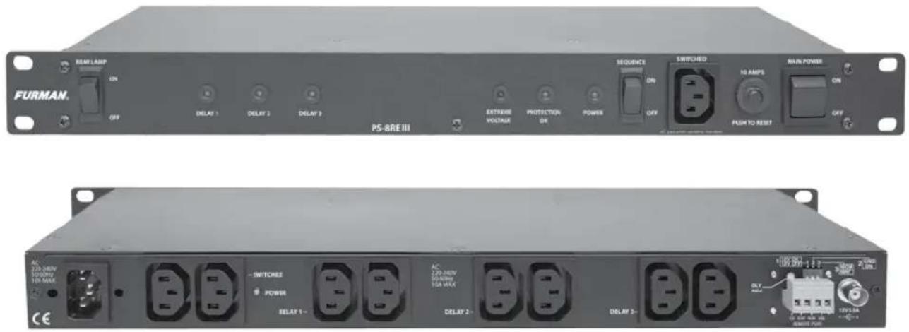
SWITCHED POWER DELAY 1- DELAY 2- DELAY 3 -AC Inlet IEC-C14, Male with Metal Retainer Clip For connecting included 2.5 m AC Power Cord.
Switched Outlets Bank
With Swtched Outlets Bank LED indicator.
Delay 1, 2 and 3 Outlets Banks Sequenced:
Sequencing Enabling On/Off Switch on Front Panel
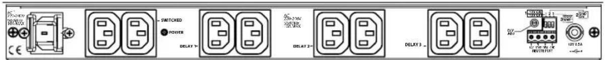
Delay Adjustment
The delay interval, which is the time between the turn-on / turn-off of consecutive delay outlets 1 and 2, or 2 and 3, is factory preset to approximately 5 seconds. It is possible to lengthen or shorten the delay interval by changing the position of the DLY-ADJ trim pot located on the right side of rear panel.
The delay adjustment procedure is simple and requires a small standard screwdriver. The DLY ADJ (delay adjustment) is a trim pot that is located on the rear of the PS-8RE III above the legacy interface and to the left of the DIP Switches. Locate the rectangular slot in the center of the trim pot and use a screwdriver the rotate the trim pot to set your desired delay. The minimum delay (1/2 Second) is achieved when the trim pot is adjusted fully counter-clockwise. The maximum delay (\~10 Seconds) is achieved when the pot is rotated fully clockwise.
text_image
DLY-ADJ Position Stage Delay 12V ON 12V OFF 1 2 3 MOM MNT 2 GND ON 12V 0.5A -- + 12V STAF REM GND REMOTE PORT Full CCW ½ Second 12 o'clock 5 Seconds Full CW 10 SecondsFig. A
text_image
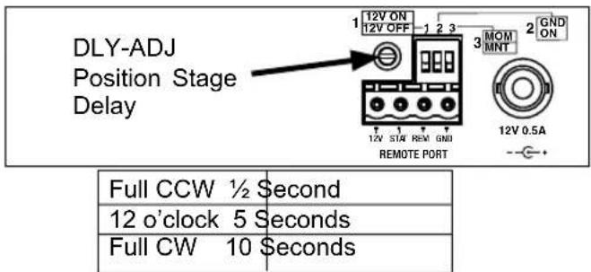
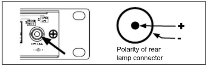
310CM MHT 2 OND ON 12V 0.5A Polarity of rear lamp connectorRear Lamp Socket
The PS-8RE III features a rear rack BNC socket which will accept any 12 VDC or 12VAC up to 12 Amp gooseneck lamp assembly, (such as the Furman GN-LED or GN-I).
Simply slide the BNC plug over the socket and rotate clockwise until both connectors snap into the locked position. The rear rack lamp can be powered ON or OFF with the Rear Lamp power switch which is located on the far left side of the front panel.
Note that the rear lamp socket is powered by 12 Volts DC and is therefore polarized. The lamp connector is polarized center positive (Figure A). If you are using a polarized lamp, please make sure that the lamp is polarized center positive. Most LED and incandescent lamps are polarity independent.
Remote Interface
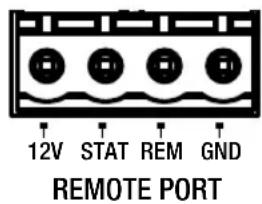
The PS-8RE III has a remote interface which can be used to control the PS-8RE III remotely using a Furman RS-1 (Maintained) or RS-2 (Momentary) wall switches. In the most basic, single unit configuration, only two wires and a switch are required to initiate a remote ON or OFF sequence. The switch may be either a momentary or maintained-contact type. If a third & fourth wire are available, an LED "Status Light" can be installed at the remote switching location to indicate the status of the PS-8RE III. The pins on the remote interface are described below:
| 1 2 3 4 12V STAT REM GND REMOTE PORT | ||
| Remote Interface | ||
| Pin Label Description | ||
| 1 12V 12VDC @12mA General Purpose Output | ||
| 2 STAT Output status LED | for driving an external | |
| 3 REM Input for controlling the sequencer remotely | ||
| 4 GND Ground (12VDC Power Common) | ||
PIN 1 +12VDC (12VDC Voltage Source)
The +12VDC terminal pin is a general purpose, 12VDC voltage source relative to the GND (#4) pin. It is provided to allow the user to control the operation of the sequencer
in "Legacy" mode by feeding the +12VDC signal back into the REM terminal input; which is pin #3 on the same connector.
PIN 2 STATUS (Output)
The STAT (status) terminal is an output that may be used to activate an LED to indicate the status of the PS-8RE III. If the STAT terminal is high, the PS-8RE III Delay outlets are either ON, or are in the process of sequencing ON. If the STAT terminal is low, the PS-8RE III Delay outlets are OFF. To use the STAT terminal output simply connect an LED between the STAT and GND with the Cathode (flat) side of the LED oriented toward the GND pin (Pin #4). Do not use a series current limiting resistor. If the LED does not light when the remote switch is ON, check the polarity of the LED and reverse the leads if necessary.
- If the LED is OFF, the DELAY outputs are OFF
- If the LED is ON, the DELAY outputs are ON
- If the LED is blinking, the DELAY 1,2 or 3 outputs are in transition either from ON to OFF or OFF to ON
PIN 3 REMOTE (Input)
The REM (remote) terminal is provided to allow remotely connected devices to sequence the PS-8RE III ON or OFF. The REM terminal has been designed to work with voltages from 5 to 30VDC. Filtering has been added to this input to prevent false triggering. The behavior of the PS-8RE III is controlled by the combination of the signal presented at the REM terminal input, and the arrangement of the rear panel DIP switches. Please refer to DIP SWITCH section for more details.
PIN 4 GND (Remote Interface Common)
The GND (ground) terminal pin serves a ground reference point for all other pins on the Remote Interface. GND can also be fed back into the REM pin (Pin #3) to activate the sequence when the PS-8RE III has been configured for GND ON mode. Please note that the GND terminal on the Remote Interface is not the same as chassis ground.
text_image
12V STAT REM GND REMOTE PORTDIP Switch
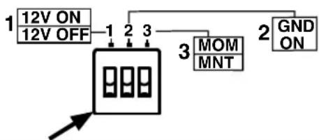
A rear panel three position DIP switch is used to set the sequence mode (+12V ON, +12V OFF, GND ON, Mom/Maint) which defines how the PS-8RE III will react to the signal presented on its REM input. The table below summarizes the behavior which is described in further detail below. Note that DIP switch position 2 overrides the setting of DIP switch 1, and DIP switch 3 overrides switches 1 and 2.
flowchart
graph TD
    A["12V ON\n12V OFF"] --> B["1"]
    B --> C["2"]
    C --> D["3"]
    D --> E["MOM\nMNT"]
    E --> F["2"]
    F --> G["GND\nON"]
| 1 2 3 | DIP 112V ON | DIP 2GND ON | DIP 3MOM/MNT | MODE | Note: The front panel SEQUENCE ON/OFF switch acts as an override. The SEQUENCE switch must be in the ON position for any of the sequenced outlets to be activated. |
| OFF | OFF | OFF | +12V OFF | Sequences the PS-8RE III ON when REM = Open CircuitFACTORY DEFAULT SETTINGSequences the PS-8RE III OFF when REM = 12VDC | |
| ON | OFF | OFF | +12V ON | Sequences the PS-8RE III ON when REM = 12VDCSequences the PS-8RE III OFF when REM = Open Circuit | |
| OFF | ON | OFF | GND ON | Sequences the PS-8RE III ON when REM is connected to GND terminal.Sequences the PS-8RE III OFF when REM = Open Circuit | |
| ON | ON | OFF | GND ON | ||
| OFF | OFF | ON | Momentary | Sequences the PS-8RE III from ON to OFF or OFF to ON each time +12V is applied to the REM input. | |
| ON | OFF | ON | Momentary | ||
| OFF | ON | ON | Momentary | ||
| ON | ON | ON | Momentary |
DIP Switch position #1 (Factory default is OFF)
DIP Switch position 1 defines how the PS-8RE III will behave when +12VDC is applied to the REM pin on the Remote interface. If this switch is in the ON position, the PS-8RE III will sequence ON when +12V is applied to the REM input. If this switch is in the OFF position (+12V OFF) the PS-8RE III will sequence OFF when +12V is applied to the REM input. DIP switches 2 and 3 must be in the OFF position (Maintained mode).
DIP Switch position #2 (Factory default is OFF)
DIP Switch position 2 defines how the PS-8RE III will behave when GND is applied to the REM pin on the Remote interface. If this switch is in the ON position, the PS-8RE III will sequence ON when GND is applied to the REM input. If this switch is in the OFF position the PS-8RE III will follow the behavior defined by DIP Switch #1. DIP switch 3 must be in the OFF position (Maintained mode).
DIP Switch position #3 (Factory default is OFF)
DIP Switch position 3 defines the switching preference for switches or devices connected to the REM pin on the Remote Interface. If this switch is in the ON position, the PS-8RE III will operate in Momentary mode. If this switch is in the OFF position the product will operate in Maintained mode.
Maintained switches, for example toggle switches or latching push-ON / push-OFF push button switches maintain their contact position until the switch is actuated a second time. Thus a switch that is closed will remain closed until the switch position is changed.
Momentary switches, for example non-latching push button switches, (including the Furman RS-2) are momentary contact devices that maintain their contact position (open or closed) only as long as the switch is held in a given position. When the actuator is released, the switch reverts to its normal position.
A switch of either kind may be used to actuate the PS-8RE III's remote operation. Maintained switches are generally most convenient when there is only one remote switch location used to control the PS-8RE III. When more than one switching location is required, momentary switches, operating in parallel allow the PS-8RE III to be sequenced ON or OFF from multiple locations
Connecting Multiple PS-8RE III Units Together
Multiple PS-8RE III units can be linked together (via their remote interface) to control large AV systems. There are two basic connection methods for the PS-8RE III; Serial and Parallel. The connection method you use may be series, parallel, or a combination thereof and will depend upon the requirements of your specific installation.
PS-8RE III in Series Mode
Series mode connection is normally used when more than three delay stages are needed. Combining PS-8RE III units in series requires an external 240 VAC coil SPST relay to trigger secondary (downstream) units. When connecting PS-8RE III units in series, the coil of the relay is plugged into one of the DELAY 3 outlets on the primary (upstream) unit.
PS-8RE III in Parallel Mode
Parallel mode can be used to activate loads in excess of 10 Amps by distributing the loads over one or more PS-8RE III units. When connected in parallel (see figures B and C) all connected PS-8RE III units will activate their DELAY 1 simultaneously. The activation times of DELAY stages 2 and 3 will depend upon the delay setting of each unit. If PS-8RE III units are operating in parallel to increase load capacity, each unit should be connected to an independent AC circuit rated at 10 amps or more. If in doubt, please consult with a qualified electrician to verify that your facility can support the load currents required for your installation.
Connecting Multiple PS-8RE III Units in Parallel
Parallel Maintained Mode:
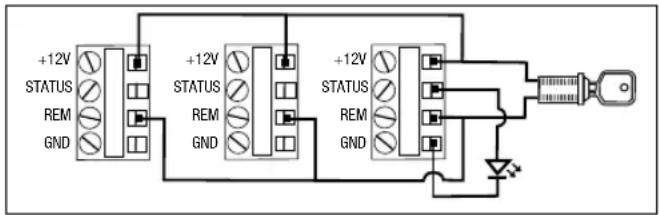
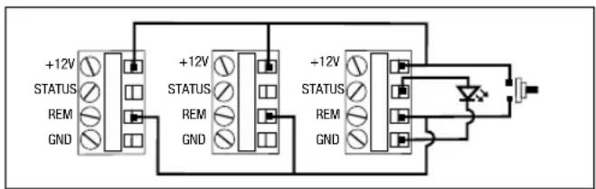
To control multiple PS-8RE III units with a single remote switch; connect the REM, +12V, and GND terminals of all units in parallel (Figure B). Make sure that the DIP #3 is OFF and the positions of DIP #1 and DIP #2 on all connected units are set to the same position. Connect a single maintained switch (such as the Furman RS-1) to the nearest PS-8RE III.
Parallel Momentary Mode
To control multiple PS-8REIII units with multiple switches, use Momentary mode (DIP #3 ON) and connect the REM, and +12V, terminals of all units in parallel (Figure C) and connect one or more momentary contact switches in parallel with the REM, and +12V terminals. All connected units will change state (from ON to OFF, or OFF to ON) each time one of the switches are pressed.
Helpful Hint: Breaker trips or unauthorized front panel operation can cause units operating in Momentary mode to fall out of sync. To restore sync, press and hold the remote switch (Figure C) for more than 4 seconds. This
text_image
+12V STATUS REM GND +12V STATUS REM GND +12V STATUS REM GNDFig. B Three PS-8RE III units configured for Parallel Maintained mode with LED indicator.
text_image
+12V STATUS REM GND +12V STATUS REM GND +12V STATUS REM GNDFig. C Three PS-8RE III units configured for Parallel Momentary mode with LED indicator.
will force all linked units into the OFF state. Linked units can also be re-synced by cycling AC power to all connected units.
Connecting Multiple PS-8RE III Units in Series
text_image
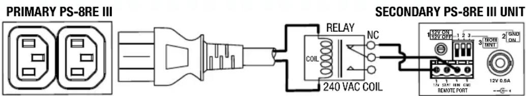
PRIMARY PS-8RE III SECONDARY PS-8RE III UNIT RELAY NC COIL 240 VAC COIL 12V ON 1 2 3 12V OFF 3 MOM 2 GND TANT 1. 3. 1. 1. 1. 1. 1. 1. 1. 1. 1. 1. 1. 1. 1. 1. 1. 1. 1. 1. 1. 1. 1. 1. 1. 1. 1. 1. 1. 1. 1. 1. 1. 1. 1. 1. REMOTE PORT 12V 0.5ASeries Maintained Mode
To operate multiple PS-8RE III units in series using a single remote switch; connect a maintained contact switch between the REM and +12V on the primary unit and connect a 240VAC coil relay (TE P/N 1649341-2) between the DELAY 3 outlet on the primary unit and the REM and +12V pins on the secondary unit. Continue connecting PS-8RE III units following this same pattern until all units have been connected.
When the primary unit sequences ON the relay will activate as soon as the DELAY 3 outlet on the primary unit has been activated. This will cause the secondary unit to begin to sequence on.
- In series mode, the DELAY 3 outlets of the primary unit and the DELAY 1 outlets of the secondary unit will activate simultaneously.
- When sequencing off series connected units, the secondary units will begin to sequence off as soon as the DELAY 3 outlets on the primary unit turn off. This means that both the primary and secondary units will sequence off at the same time. In other words, sequencing ON and sequencing OFF are not equivalent. If your installation requires symmetrical sequencing please consult Furman customer support for other product options.
Troubleshooting
PS-8REIII shows no signs of life – no lights or activity
- Confirm that unit is receiving 220 – 240 VAC power
- Confirm that the front panel breaker is pushed in
PS-8REIII Power lamp is on, but unit does not sequence
- Confirm that the sequence switch is in the ON position
- Confirm that the signals present at the remote interface allow sequencing
- If in doubt, return the PS-8REIII to factory default settings and re-test
PS-8REIII Power lamp is on, but PROTECTION OK LED is dim or off
- Surge protection circuit has been damaged; return unit to Furman authorized repair facility for service
PS-8REIII operates, but trips circuit breaker
- Check loads on all outlets, reduce if necessary
- Check loads on branch circuit, reduce if necessary
Compatible Furman Products
text_image
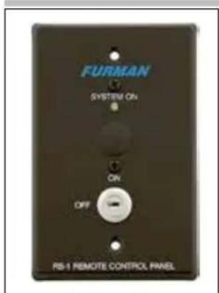
FURMAN SYSTEM ON ON OFF RS-1 REMOTE CONTROL PANELRS-1 – Remote Key Switch
text_image
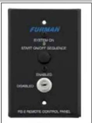
FURMAN SYSTEM ON START ON/OFF SEQUENCE ENABLED DISABLED PS-E REMOTE CONTROL PANELRS-2 – Remote Key Switch w/ Push Button

natural_image
Close-up of a black cable with a metallic connector (no text or symbols visible)GN-LED LED Gooseneck Lamp

natural_image
Black USB cable with a connector, isolated on white background (no text or symbols)GN-I – Incandescent Gooseneck Lamp
PS-8RE III SPECIFICATIONS
Maximum AC Current Rating:
• 10 Amps, 220 - 240 VAC @ 50 - 60 Hz (Thermal breaker)
AC Cord:
- 1 mm2 x 3, 2.5 m length, IEC-C13 (Female) to CEE-7/7 Schuko plug.
AC Inlet:
• IEC-C14 (Male) with metal wire retainer clip
AC Outlets:
- Convenience Outlet (Front Panel) 1 Switched IEC C-13
- Rear Panel Outlets: 2 Switched IEC C-13 (1 duplex),
- 6 Sequenced IEC C-13 (3 duplexes each controlled by separate relay)
AC Surge Protection:
- Spike Protection Mode: Line to neutral, zero ground leakage
- Spike Clamping Voltage: 376VAC peak @ 6,000 Volts /3,000 Amps
- Response Time: 1 nanosecond
• Maximum Surge Current: 6,500 Amps
• AC Overvoltage Protection: EVS, 275VAC+/-5VAC
• AC Overvoltage Reset Modes: Auto
AC Filtering:
• LiFT
- Noise Attenuation: 10dB @10KHz, 40dB@100KHz, 50dB@500KHz
Operating Temperature Range:
- 5C (40F) to 40C (105F) degrees
Humidity Range: • <90% rH (Relative Humidity)
User Interface:
- Rocker Switch: Front panel, Power (ON, OFF)
- Rocker Switch: Front panel, Sequence (ON, OFF)
- Rocker Switch: Front panel, Rear Lamp (ON, OFF)
• Thermal Circuit Breaker: Front panel, pushbutton
- Front panel diagnostic indicators DELAY 1, DELAY 2, DELAY 3, Power, EVS, and Protection OK
- Rear panel BNC Lamp connector 12VDC / 12 Amp
• Control/Status/Triggering (Rear Panel):
- Rear Panel DIP Switches: 12V Mode On/Off, GND Mode On, Momentary/Maintained
- Potentiometer: Rear panel, time calibration fine tune delay adjust
- Remote Terminal: +5-30VDC In, 12VDC (12mA) Out
- Remote Terminal: Phoenix type 4-Pin Connector with
Screw terminals: +12V, STAT, REM, GND (Class 2 Wiring)
Size: 44.33 mm x 482.6 mm x 165.1mm (HWD)
Mass: 3.03 Kg
Power Consumption (No Load): 10 Watts
Safety Agency: TUV
Specifications are subject to change without notice due to product improvements and upgrades.
THREE YEAR PRODUCT WARRANTY
Furman warrants to the original purchaser of this product for a period of three (3) years from the date of purchase, that the unit shall be free of defects in design, material or workmanship, and Furman will repair or replace any defective unit. Full Warranty and Policy information available at: www.furmansound.com
CAUTION! WARRANTY LIMITATION FOR INTERNET PURCHASERS
Furman products purchased through the Internet do not carry a valid Product Warranty unless purchased from an Authorized Furman Internet Dealer and the original factory serial numbers are intact (they must not have been removed, defaced or replaced in any way). Purchasing from an Authorized Furman Internet Dealer insures that the product was intended for consumer use, has passed all quality inspections and is safe. Buying through auction sites or unauthorized dealers may result in the purchase of salvaged and/or failed products. In addition, Authorized Furman Internet dealers have demonstrated sufficient expertise to insure warranty compliant installations. For a list of Authorized Furman Internet Dealers please go to www.furmansound.com
FURMAN®
1800 S. McDowell Blvd., Petaluma, California 94954 USA www.furmansound.com E-mail: info@furmansound.com
DIN-00032-A - ENGLISH
PS-8RE III
Inverter / Sequenzer
text_image
FURMAN. PS-8RE III RESEARCH OR OR DELAY 1 DELAY 2 DELAY 3 EXTREME VOLTAGE PROTECTION OR POWER SEQUENCE SWITCHER OR OR SWITCHED TO AMPS AND POWER PUSH TO RESET ON OFF CE AC- 720-240V SOMWY 110 MHz ~SWITCHED POWER DELAY 1- DELAY 2- DELAY 3- DCB 10A WXK DCB 10A WXK DCB 10A WXK DCB 10A WXK DCB 10A WXK DCB 10A WXK DCB 10A WXK DCB 10A WXK DCB 10A WXK DCB 10A WXK DCB 10A WXK DCB 10A WXK DEUT PowerEinführung
LiFT (Linear Filtering Technology)
Switched IEC C-13, maximal 10A.
text_image
PRIMARY PS-8RE III SECONDARY PS-8RE III UNIT RELAY NC COIL 240 VAC COIL 1 12V ON 12V OFF 1 2 3 3 MOM MNT 2 GND ON 12V 0.5A REMOTE PORTnatural_image
Close-up of a black cable with a connector, isolated on white background (no text or symbols)GN-LED LED- Schwanen- halslampe

natural_image
Black flexible microphone with a black connector, isolated on white background (no text or symbols)G-NI -Schwanenhals- Glühlampe
- Remote-Terminal: 5-30 VDC In, 12VDC (12mA) Aus
text_image
PRIMARY PS-8RE III SECONDARY PS-8RE III UNIT RELAY NC COIL 240 VAC COIL 1 2 3 1 2 3 12V ON 12V OFF 3 MOT TANT 2 GND ON 12V 0.5A → - 4PS-8REIII operates, but trips circuit breaker
natural_image
Close-up of a black cable with a connector, isolated on white background (no text or symbols)natural_image
Black flexible microphone with a black connector (no text or symbols visible)TROIS ANS GARANTIE PRODUIT
natural_image
Close-up of a black flexible cable with a metallic connector (no text or symbols visible)natural_image
Black flexible microphone with a curved tip, isolated on white background (no text or symbols)1800 S. McDowell Blvd,