
SmartSequencers CN-20MP - Power Regulator Furman - Free user manual and instructions
Find the device manual for free SmartSequencers CN-20MP Furman in PDF.


| Type | AC Power Sequencer |
| Model | CN-20MP |
| Brand | Furman |
| AC Current Rating | 20 Amps @ 120 VAC |
| Power Capacity | 2400 Watts |
| Number of Outlets | 2 (1 duplex NEMA 5-15R) |
| Power Cord | 12 AWG, 10 ft (3.05 m), NEMA 5-15P |
| Overvoltage Protection | EVS, 145 VAC ±5% |
| Undervoltage Protection | EVS, 77 VAC ±5% |
| SmartSequencing | Yes, daisy-chain up to 1000 ft using 22 AWG wire |
| Remote Control | 5-pin Phoenix: +12VDC, STAT, REM, GND, DLY OUT |
| Force Off Input | 2-pin Phoenix, configurable normally open/closed |
| User Interface | DIP switches, delay pot, bypass switch, LED indicators |
| Operating Temperature | 5°C to 40°C (40°F to 104°F) |
| Humidity Range | < 90% RH |
| Power Consumption (No Load) | 10 Watts |
| Safety Compliance | NRTL-C CSA/NRTL |
| Warranty | 15-Year Limited |
| Cleaning | Use only a dry cloth |
Frequently Asked Questions - SmartSequencers CN-20MP Furman
User questions about SmartSequencers CN-20MP Furman
0 question about this device. Answer the ones you know or ask your own.
Ask a new question about this device
Download the instructions for your Power Regulator in PDF format for free! Find your manual SmartSequencers CN-20MP - Furman and take your electronic device back in hand. On this page are published all the documents necessary for the use of your device. SmartSequencers CN-20MP by Furman.
USER MANUAL SmartSequencers CN-20MP Furman
CONTRACTOR SERIES SmartSequencer™
MINIPORT CN-15MP and CN-20MP Instructions
Contractor Grade Power Management with SmartSequencing™ Technology
Features:
SmartSequencing™ technology allows large complex A/V systems to be safely power cycled on and off sequentially, with the press of a button.
Extreme Voltage Shutdown (EVS) with safeguards against operation during under and over voltage conditions.
Security features include cover shield to prevent tampering with switch settings.
Forced Off immediate shutdown: for safety and fire ordinance compliance.
Multi-Color LED Indicators for status functions.
2 Power Outlets on 1 bank providing 1800 Watts of AC power (CN-15MP) and 2400 Watts of AC power (CN-20MP).
CN-15MP - 10 ft. Power Cord 14AWG CN-20MP - 10 ft. Power Cord 12AWG
15 Year Limited Product Warranty
Introduction
Congratulations and thank you for choosing the Furman CN-15MP or CN-20MP Miniport. We assure you that your Miniport will provide many years of trouble free operation. The Miniport Power Sequencer is equipped with Furman's exclusive SmartSequencing™ technology. SmartSequencing™ defines a whole new level of power management and control while streamlining installations from start to finish.
Why choose Furman?
At Furman Sound, we have spent the last 30 years quietly obsessing about professional audio and how to best separate your equipment from the noise and damage often associated with AC power. Over the years we have developed a multitude of technologies that have spared countless devices from damage and earned the trust and respect of the Professional A/V industry. The Contractor series represents the culmination of our engineering expertise and leverages more than 30 years of experience.
Why choose AC power sequencing?
Many pro audio/video installations need audio power amplifiers to activate last. Our solution is the AC power sequencer. The power sequencer provides AC power to outlet groups one at a time, thus allowing equipment to be powered up and down in an orderly fashion by first providing power to signal processing equipment and then providing power to the amplifiers. When shutting down the A/V system, a sequencer will turn off the system in the reverse order, hence the amps will be turned off first, and then the signal processing equipment will be turned off last.
This is necessary because, as most sound reinforcement professionals know, the majority of equipment damage occurs when devices are either being powered up or powered down. Power sequencing allows equipment to power up in sequence which prevents the dreaded speaker “pop” associated with on off switching of signal processing equipment while the audio power amplifiers are energized. If the signal processing “pop” is amplified sufficiently, the result can damage amplifiers and speaker components. Because it prevents this unwanted, and often costly, circumstance, AC power sequencing is extremely valuable.
Furman Contractor Series equipment allows sound reinforcement equipment to be remotely powered up or powered down over a large distance, not just in the immediate vicinity of the operator. A remotely mounted switch or control pad can be used to sequence equipment on or off. In addition, Furman Contractor Series remote functions can be initiated across a room, on-site, or off-site with our BlueBOLT technology.
The Miniport SmartSequencer fulfills many power sequencing requirements that have very difficult to achieve in the past. Furman SmartSequencing™ delivers an end-to-end solution right out of the box! Please review this manual to discover how the Miniport with SmartSequencing™ can deliver professional results for you.
Before You Begin Inspect Upon Receipt
The box should contain the following items:
1) Miniport CN-15MP or CN-20MP
2) Quick Start Guide
3) Phoenix-Type Connectors
CN-15MP

CN-15MP

CN-15MP Quick Start Guide

3 Phoenix Type Connectors
CN-20MP

CN-20MP
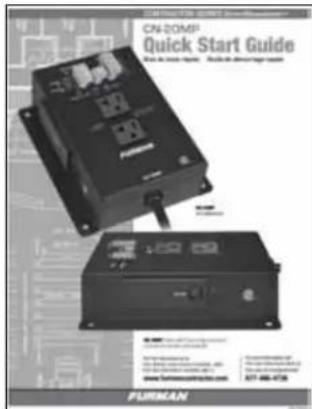
CN-20MP Quick Start Guide

3 Phoenix Type Connectors
Table of Contents
| Feature Descriptions | 2 |
| Important Safety Instructions | 3 |
| Abbreviated Product Features | 3 |
| Set Up Diagrams | 4 & 5 |
| SmartSequencingTM101 | 6 |
| Side Panel Overview | 7, 8 & 9 |
| Front Panel Overview | 10 & 11 |
| Setup and Troubleshooting | 11 |
| Single Unit Set Up | 11 |
| Multiple Unit Set Up | 11 |
| Breaker Overload | 11 |
| Re-syncing Multiple Sequencers | 12 |
| Specifications | 12 |
| 15 Year Limited Warranty | 12 |
SmartSequencing™
Furman SmartSequencing ™ is a contractor-friendly technology that makes AC power sequencing easy to employ by non-technical personnel. Using SmartSequencing technology, multiple Furman Contactor Series units can be linked together over distances up to 1000 feet using inexpensive two conductor wire. These same two wires not only control the sequencers, but also form the backbone of an amazingly robust and reliable communication system through which information about status, voltage, current, and power can be queried from any device in the SmartSequencing network.
Generally, high-priced automation systems are used for large, innovative installs, yet these control systems seldom combine AC power distribution and bidirectional sequencing. SmartSequencing™ provides the answer right out of the box by offering a simple approach to AC power management and control. Furman's newest power sequencing technology is an end-to-end solution that is operational up to 1000 feet via a non-polarized, isolated current loop. In situations where power sequencing is critical, or more than one AC electrical circuit is utilized, wiring Furman SmartSequencing™ products in series is simple, fast and reliable.
EVS (EXTREME VOLTAGE SHUTDOWN)
Furman's trusted (EVS) over-voltage detection protects against prolonged over-voltage conditions, such as accidental connections to 208 or 240 VAC or an intermittent loss of neutral. It does so by continuously monitoring the incoming AC voltage and when an unsafe condition is detected, a relay shuts off the power to the outlets until the overvoltage condition has subsided. The Miniport also allows the EVS shut-down feature to be overridden. The Extreme Voltage Shutdown technology is a tremendous asset.
Remote Access (and BlueBOLT®)
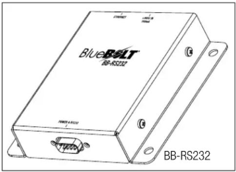
The Miniport is a member of Furman's Contractor series of devices. All members of the Contractor series can be controlled remotely using an integral data-link and command API. The remote access feature delivers integration with various control systems. The API provides a rich set of commands and queries that allow remote control and situational awareness over large distances. Furman's optional BlueBOLT® RS-232-to-Ethernet adaptor provides additional control programming and monitoring from any Web-enabled device via Telnet, direct HTTP connection, or www.mybluebolt.com
Security and Safety
The Miniport is readily adaptable to a wide range of installation requests and requirements. It was designed from the ground up to be out-of-box compatible with Furman legacy and third party equipment. Forced Off inputs and selectable DIP switch settings are provided to allow easy interface to devices, such as alarm systems.
Additional Features
The Miniport is equipped with LED indicators to provide visual aid in tracking conditions such as power, protection, sequencing and communication. The Miniport CN-15MP is supplied by a 14 AWG, 10 foot AC cord. And the Miniport CN-20MP is supplied with a 12 AWG, 10 foot AC cord.
All Contractor Series units are backed by our exclusive 15 year Limited Warranty
Important Safety Instructions
-
Please read and follow all instructions.
-
Please keep these instructions.
-
Please heed all warnings.
-
WARNING: This device is intended for indoor use only. Do not use this device near water. To reduce the risk of fire or electric shock, do not expose this device to rain or moisture.
-
CAUTION: To reduce risk of shock, please disconnect the CN-15MP / CN-20MP Sequencer from AC power before servicing any equipment connected to the CN-15MP / CN-20MP Sequencer.
-
Clean only with dry cloth.
-
CAUTION: Do not install near any heat sources such as radiators, heat registers, stoves, or other equipment that may produce heat.
-
Protect the power cord from being walked on or pinched, particularly at plugs and the point where they exit the device.
-
Please, only use accessories specified by the manufacturer.
-
Refer all servicing to qualified personnel. Servicing is required when the unit has been damaged in any way or fails to operate.
-
WARNING: Do not use power cord as the main power disconnect. The device is intended for AC power sequencing.
-
Do not defeat the safety purpose of the polarized plug. A polarized plug has two blades, with one wider than the other. The wide blade is provided for your safety. If the provided plug does not fit into your outlet, consult an electrician for replacement of the obsolete outlet. (*See below for 20A plug)
-
Do not defeat the safety purpose of the grounding prong. A ground type plug has two blades and a third grounding prong. The third prong is provided for your safety. If the provided plug does not fit into your outlet, consult an electrician for replacement of the obsolete outlet.
-
WARNING: This device must be connected to an AC outlet with a protective earth ground connection.
ABBREVIATED PRODUCT FEATURES
EXAMPLE 1 DIAGRAM - SMALL SmartSequencing SET-UP
![graph TD A["RS-2 Momentary Remote Switch"] --> B["CN-1800S"] B --> C["BACK PANEL TERMINALS"] C --> D["FORCE OFF"] D --> E["CLASS 2 WIRING 24 AWG RECOMMENDED"] E --> F["FIRE ALARM (2 POLE) IMMEDIATE FORCED OFF WITH SHORT"] F --> G["CN-20 MP"] G --> H["DIP SWITCH SET"] H --> I["POWERED ARRAYS"] I -->…](/content/2026/05/955315/images/f59c918b1b796f6402b91efe45fbac3e330de2807e77a6841621a03395483b90.jpg)
EXAMPLE 2 DIAGRAM - SMARTSEQUENCING SET-UP - SAMLL LEGACY UPGRADE

EXAMPLE 3 DIAGRAM - LARGE LEGACY UPGRADE
![graph TD A["RS-1 Maintained Key Switch"] --> B["ASD-120"] B --> C["CS: FORCE OFF, REM COMM, GND, RLY COMM, F"] C --> D["Class 2 WIRING 24 AWG RECOMMENDED"] D --> E["This upgrade is based upon scenario number 3 in the ASD-120 manual. The new example substitutes CN-2400S units at the old miniport loca…](/content/2026/05/955315/images/f223e81e65cfe24ca6098e77a3bda2155f0334cfa96b5b4e981b077f90cac753.jpg)
EXAMPLE 4 DIAGRAM - LARGE SET-UP PRIMARY CONTROLLED VIA RS-232
![graph TD A["CN-1800S"] --> B["UNIT 1"] A --> C["UNIT 2"] A --> D["UNIT 3"] A --> E["UNIT 4"] A --> F["UNIT 5"] B --> G["PRIMARY INTERFACE"] C --> H["SECONDARY INTERFACE"] D --> I["SECONDARY INTERFACE"] E --> J["SECONDARY INTERFACE"] F --> K["SECONDARY INTERFACE"] G --> L["FIRE ALARM 3 POLE"] H --> M…](/content/2026/05/955315/images/5995424fd9e0cc7d3ca289efa1937ae2ce063da67877ceaf28d499abdfc1f682.jpg)
SmartSequencing™ 101
SmartSequencing requires that a pair of wires be connected between the Primary OUT terminals of one sequencer to the Secondary IN terminals of a second sequencer. SmartSequencing is polarity independent, so it does not matter which terminals are used at the IN port or the OUT port. Two wire runs connecting two or more units create a SmartSequencing chain.
![graph LR A["PRIMARY"] --> B["OUT"] B --> C["IN"] D["SECONDARY"] --> E["OUT"] E --> F["IN"] G["SECONDARY"] --> H["OUT"] H --> I["IN"]](/content/2026/05/955315/images/2d8e82f5865a03ac40ad04b2b8f45a51140e5e3d95e39419996a65f1eb917879.jpg)
Furman SmartSequencing™ products can be connected end-to-end to form a chain of sequencers. Each Contractor Series unit has two communication ports (OUT and IN) divided into 4 terminals, responsible for half-duplex transmissions via two bi-directional current loops. The messages between connected devices are communicated in the form of ASCII character strings utilizing a proprietary data link protocol.
The first SmartSequencer within a chain is referred to as the "Primary" or "Primary Unit". The Primary unit controls the other sequencers in the chain. The other sequencers are termed "Secondary" or "Secondary Units". The Primary Unit only has one active current loop because the Primary Unit only has one Secondary sequencer attached to it. Secondary units have two active current loops because they are inserted between two sequencers. A chain of sequencers is created by connecting the PRIMARY OUT terminals of one sequencer to the Secondary IN of the next downstream sequencer.
A Furman SmartSequencing™ chain communicates using a bucket brigade technique. A Primary Unit communicates to the first Secondary Unit downstream by sending commands out of its Primary OUT terminals to the Secondary IN terminals of the first downstream Secondary Unit. If there is an additional Secondary Unit in the chain, the first Secondary Unit will communicate to the additional Secondary Unit using its Primary OUT terminals to the second Secondary Unit's Secondary IN terminals. This continues down the sequence chain until the last Secondary Unit. The last Secondary Unit will receive commands into its Secondary IN terminal port but will not use its Primary OUT terminal port (because there are no Secondary Units after it). Please see figure above:
SmartSequencing™ commands between units are always accepted when continuity exists, however SmartSequencing commands that control the outlets are not always honored. This may occur if the Miniports switch settings of conditions conflict with the requested SmartSequencing command. For example: BYPASS switch, REMOTE Input, EVS, or FORCE OFF may have priority over the SmartSequencing command.
Additional SmartSequencing™ information is available throughout this manual and also on the website www.furmancontractor.com. Details such as connection diagrams and a Quick Start Guide, etc., can also be found at the website.
Side Panel Overview

Bypass Switch
The BYPASS push button switch is located on the side panel to the right of the DIP Switch. A hole in the security cover provides access to the BYPASS switch even when the security cover is installed.
The BYPASS switch has a dual purpose:
The BYPASS switch is provided to allow a layperson to activate the outlets if the external control system is either inaccessible or commanding the outputs to an OFF state. It should be noted that the FORCE OFF and EVS conditions have priority over the BYPASS switch and if either of these conditions are true, the outlets will be deactivated regardless of the position of the BYPASS switch. The BYPASS switch operates in a push on/push off mode and latches either on or off. If the switch is pushed on, the outlet will remain powered until the switch is pressed a second time and latches in the off state.
The BYPASS switch is also used to clear the FORCE OFF error. If the unit is in FORCE OFF mode, and the conditions at the FORCE OFF inputs that spawned the FORCE OFF error have been removed, the user can use the BYPASS switch to clear the FORCE OFF error by quickly toggling the BYPASS switch ON/OFF.
DIP Switch and Delay Adjustment
The DIP Switch is found near the center of the side panel, under the Security Cover. You can access the DIP switch by removing the security cover screw using a small Philips screwdriver. The DIP Switch is used to set various options. It is also used in combination with the DLY ADJ pot to the ON/OFF delay.

NOTE: The DIP switch ON / OFF settings are indicated as shown below throughout this manual.

DIP SWITCH DEFAULT SETTING
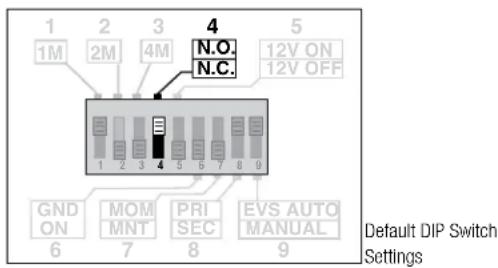
Switches are factory pre-set as shown below. Switches 1, 4, 8, and 9 are up (ON) position.

Default DIP Switch Settings
DIP 1, 2, & 3 and the Delay Adjustment
DIP Switch positions 1, 2 and 3 are used to define the time delay or "dwell" time that is imposed between activating/deactivating consecutive devices within a chain of sequencers. Miniports will activate their outlet as soon as an activation message or signal has been received, but impose a delay (defined by the settings of DIP 1, 2 & 3) when forwarding the activation message to the next downstream device. When activating, the delay countdown starts after the outlet has been activated. When deactivating, the delay occurs prior to deactivating the outlet.
DIP 1 = ON adds 1 to the minute maximum time delay
DIP 2 = ON adds 2 minutes
DIP 3 = ON adds 4 minutes.
Note: The DIP switch settings are cumulative, thus if all three DIP switches are in the ON position, the maximum allowable time delay will be 7 minutes, i.e. 1min+2min+4min=7min. The factory default setting is DIP 1 ON or UP, and DIP 2 and 3 are OFF or DOWN. You can set these switches in any position you like to achieve your preferred time delay
| DIP 1 DIP 2 DIP 3 Maximum Time Delay |
| OFF OFF OFF 10 Seconds |
| ON OFF OFF 1 Minute |
| OFF ON ON 2 Minute |
| ON ON OFF 3 Minute |
| OFF OFF ON 4 Minute |
| ON OFF ON 5 Minute |
| OFF ON ON 6 Minute |
| ON ON ON 7 Minute |
Delay Adjustment
The Delay Adjustment (DLY ADJ) pot is used in conjunction with DIP 1, 2, and 3 to precisely dial in your preferred delay time. The DLY ADJ is located to the left of the DIP Switch. If this potentiometer is turned to its 100% value (fully clockwise), the time delay will be equal to the maximum time delay defined by DIP switches 1, 2, and 3. If the potentiometer is in the 12:00 o'clock position (50%), then the time delay will be 50% of the maximum time delay interval defined by the setting of DIP Switch positions 1, 2 & 3. If all three DIP switches are off, and the potentiometer is turned completely counter-clockwise, the time delay is 100 milliseconds, which is the minimum time setting. The Delay Adjustment potentiometer comes factory-set at 50%, the 12 o'clock position.
Example: If the DIP Switches are set to a 6 minute maximum delay and the potentiometer is set to its 50% setting, then the delay interval between sequenced banks will be 3 minutes. (DIP 1 OFF or DOWN, DIP 2 and DIP 3 ON or UP) x .50 = 6 minutes x .50 = 3 minutes.
DIP 4 FORCE OFF setting
DIP Switch position 4 is used to define how the Miniport will implement its FORCE OFF feature. FORCE OFF is a safety feature that is designed to cut AC power to all outlets instantaneously. Some municipalities may require this feature as a means of disabling equipment in the presence of fire or an alarm. The FORCE OFF inputs can be used with a momentary or maintained dry contact in either a Normally Open or Normally Closed state. The factory default position for DIP 4 ON or UP, or (NO) Normally Open. In this configuration, the FORCE OFF will be triggered when the FORCE OFF pins are shorted together. If DIP Switch position #4 is off (DIP 4 DOWN) the FORCE OFF pins must remain shorted for normal operation. In this configuration, the FORCE OFF will be triggered when the short between the two FORCE OFF pins is removed.
If a FORCE OFF is triggered, the FORCE OFF message will be propagated to all SmartLink connected devices. The power to all of the outlets will be disabled and the POWER LEDs will begin to blink. To clear the FORCE OFF, the FORCE OFF pins must first be cleared of the condition that originally triggered the FORCE OFF event. After this has been done you can reset the FORCE OFF in three ways:
1) Cycle the BYPASS switch on/off.
2) Cycle the power to the unit on/off
3) If you are using a rack-mounted Contractor device (CN-1800S, CN-2400S, CN-3600S) as a Primary unit, you can clear the FORCE OFF from all SmartLink connected units by turning the key to the OFF position and then back to the ON or REMOTE position.
Once FORCE OFF has been cleared, normal operation will resume. Force off (DIP 4) has priority over all other DIP switch settings, including DIP 5, DIP 6, and DIP 7 settings. Further information on DIP 5, DIP 6, and DIP 7 can be found in the sections that follow. The use of DIP 4 may or may not be a consideration for every install, yet it may be a vital feature for safety compliance. The Force Off feature is always working, despite the fact sometimes it is in a forgotten state.
Default DIP Switch Settings

Remote Port
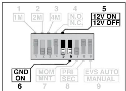
DIP 5 and 6 Remote input setting
DIP Switch positions 5 and 6 are used to define what happens when either 12VDC or GND are applied to the remote (REM) signal input. All of the signals discussed in this section appear on the REMOTE PORT connector on the top right side of the CN-15MP.
The factory default settings for DIP 5 and DIP 6 are OFF
With DIP 5 and DIP 6 OFF (factory default) connecting the 12VDC signal to the REM terminal will cause the outlet power to turn OFF. With DIP 5 ON and DIP 6 OFF, connecting the 12VDC signal to the REM terminal will cause the outlet power to turn ON. With DIP 6 ON connecting GND to the REM terminal will cause the outlet power to turn on regardless of the setting of DIP switch 5.
The table below summarizes the power outlet behavior as a function of DIP 5 and DIP 6
| DIP 5 | DIP 6 | Outlet behavior as a function of the REM signal input |
| OFF | OFF | Outlet is deactivated when REM is connected to 12VDC |
| ON | OFF | Outlet is activated when REM is connected to 12VDC |
| OFF | ON | Outlet is activated when REM is connected to GND |
| ON | ON | Outlet is activated when REM is connected to GND |
| Note that the setting of DIP switch 6 overrides DIP switch 5.If DIP Switch 6 is ON the setting of DIP switch 5 is ignored. | ||
The settings for DIP 5 and DIP 6 may be useful in situations where the existing remote key switch operates different from that which was anticipated by the factory default settings, or Furman standard wall switch products (RS-1 and RS-2). Please feel free to contact Furman tech support if further assistance is necessary.
Default DIP Switch Settings
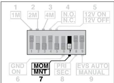
DIP Switch position 7 is used to define the switching preference for switches or devices connected to the remote (REM) signal input. The Miniport can be set to operate in a Maintained Mode (DIP 7 OFF or DOWN) or a Momentary Mode (DIP 7 ON or UP) dependent upon the preferred method of remote switching. The factory default for DIP 7 is OFF (Maintained Mode)
When operating in Maintained Mode, the REM input assumes that an external switch or device will behave like a toggle switch wherein the switch contacts remain in a given position (open or closed) until the state of the switch has been changed. Maintained switching is considered more stable because control signals must be continuously asserted to "maintain" a system in operation.
When operating in Momentary Mode, the REM Input assumes that an external switch will behave like a momentary contact (push button) switch where the switch contacts are shorted only as long as the button is pressed. The output will toggle ON or OFF each time the REM input is activated. Momentary Mode is considered more flexible than Maintained mode as multiple push button switches, such as the Furman RS-2 can be wired in parallel and used to toggle a Miniport ON or OFF from multiple locations.

Default DIP Switch Settings

Remote Port
DIP 8 Primary / Secondary setting
DIP Switch position 8 is used to define the Miniports role in the SmartSequencing™ system. In an array of sequencers connected via SmartLink, there can be only one Primary Sequencer, and multiple (up to 99) Secondary Sequencers. A Primary Sequencer sends commands to all Secondary sequencers over the SmartLink interface. If DIP Switch 8 is ON, the Miniport is set as Primary Sequencer. If DIP Switch 8 is OFF the Miniport will operate as a Secondary Sequencer.

Default DIP Switch Settings
DIP 9 EVS ON or EVS OFF setting
DIP Switch position 9 is used to define how the Miniport will behave in the presence of Extreme voltage. If DIP 9 is ON (EVS = ON) the Miniport will automatically turn off power to its outlet if the incoming power ever goes above or below tolerable conditions. If DIP 9 is OFF (EVS = OFF) the Miniport will register, but not turn off power to its outlet if the incoming power ever goes above or below tolerable conditions.
For the Miniport the over-voltage EVS triggers at 145 VAC +/- 5% and the under-voltage EVS is triggered at 77 VAC +/- 5%.
If DIP 9 is set to ON and an EVS event occurs, the Miniport will not automatically turn on after the EVS event has subsided unless the BYPASS switch is on, or the remote port has been configured to enable the outlet.
To reactivate a Miniport operating in a Smartlink, all units must be sequenced off and then back on. This can be done by sequencing the Primary unit OFF/ON.
Please note, if there is an underlying wiring fault, such as an intermittent loss of Neutral, the EVS event may continue to be encountered. If this is the case, an operator should avoid resetting the unit without first checking the source of the problem and perhaps changing the AC source.
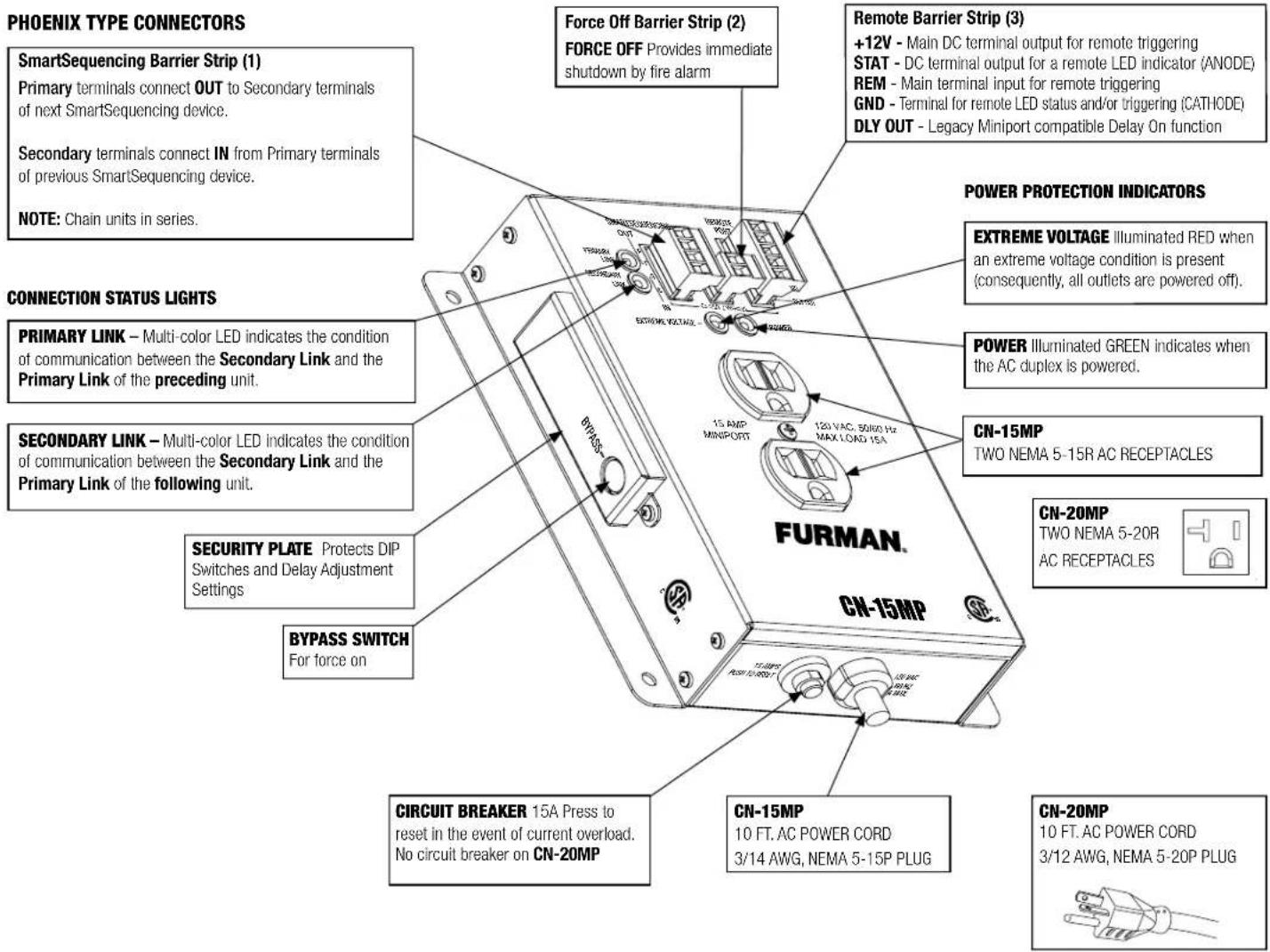
Connection Status Lights
Each multi-color Connection Status Light provides information on the Miniports' communication links. There are two LEDs, labeled PRIMARY LINK and SECONDARY LINK that are associated with the SmartSequencer link communications system. Each of these LEDs can illuminate Red, Green, or amber. When a number of Miniports are connected together via their SmartSequencer link ports, the LEDs will illuminate Green and occasionally blink as messages are passed between units.
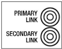
SmartSequencing Note: When there are two or more SmartSequencer units linked in series, a slowly blinking Green Primary Link LED identifies the Primary Unit. Similarly, a SmartSequencer displaying a solid Green Primary Link LED would indicate the unit is the last Secondary in the chain of sequencers. Secondary Units in the middle of the chain will display both a solid Green Primary Link LED and a solid Green Secondary Link LED. The Connection Status Link Indicators will flash accordingly during power up and power down as SmartSequencer messages are sent between units.
Green LED status is a sign of good communications. If a Contractor Series unit is used independently (no connections) and the unit is configured as a Primary Unit (DIP 8, ON or UP), the Primary Link LED will slowly blink Green at 1 second intervals. If there is a SmartSequencer link connecting a Primary Unit to a Secondary Unit, the Primary unit will send messages to the Secondary Unit and the Secondary Link LED will illuminate Green on the Primary Unit, indicating there is an established communication link with a the Secondary Unit. On Secondary units (DIP Switch 8, OFF or DOWN), the Primary Link LED will be Green, indicating there is communication to a Primary.
The Red Connection status LED can sometimes illuminate briefly if a message is lost corrupted on the SmartSequencing link. Unless the Red LED is illuminated continuously, this should be no cause for concern. The SmartSequencing protocol is robust and redundant. As long as a physical link is in place, the message will eventually get through.
A continuous Red Connection Status LED indicates that a unit has no SmartSequencing link connection where the unit has been configured to expect link communications. This occurs when a Secondary Unit cannot communicate with surrounding units in a SmartSequencing chain. The result is that the Secondary Units Primary Link LED may be Red because the link is broken to a Primary Unit or the Secondary Link LED may be Red because the link is broken to a Secondary Unit. This could also mean that the Secondary Unit sees the Primary Unit, but the Primary Unit does not see its Secondary.
The Amber LED may be seen upon start up initialization or as communication ensues between Smart Sequencers. This Amber LED state should resolve to a Red or Green state. If the amber indication does not resolve, please contact Furman Support.
Power Indicator

One POWER LED is provided to indicate the ON or OFF state of the power outlet. If power is provided to the outlet, the LED will illuminate green. If the Miniport is operating under safe power conditions and no utility fault conditions exist the POWER LED will remain steadily lit. Once triggered to power-down the POWER LED will go off as the power outlet is deactivated.
EVS LED

The EXTREME VOLTAGE LED indicator is normally OFF. The EVS function is tied to this LED and monitors the incoming voltage for out of tolerance conditions. If enabled, the EVS will disable the AC power before damage can occur. The EXTREME VOLTAGE LED will be illuminated Red anytime the voltage is found to be below 77 volts or more than 145 volts. The EVS LED will remain illuminated, and the outlets will be disabled as long as an out of tolerance condition exists.
Circuit Breaker
The CN-15MP is equipped with a 15 Amp thermal circuit breaker button which will pop outward if the amount of current distributed to all loads exceeds 15 Amperes. The CN-20MP does not have a circuit breaker.

CN-15MP Circuit Breaker

CN-20MP No Circuit Breaker
CN-15MP
If the combined current, drawn by all devices plugged into the CN-15MP exceeds 15 Amps at any time, the circuit breaker will "trip", cutting off power to all connected devices. If this occurs; the operator must reduce the load by unplugging one or more devices from the CN-15MP, and reset it. The operator can reset the circuit breaker by pressing in the circuit breaker button. However, because the safety feature is a thermal breaker, it is suggested that you wait one minute after the "trip" occurs to allow the breaker to cool down before resetting.
CN-20MP
The CN-20MP does not have an integral circuit breaker and relies on the branch circuit breaker to limit the current to the loads. The CN-20MP must be connected to a branch circuit equipped with a 20 Amp breaker, and capable of sustained 20 Amp service. If the branch circuit breaker trips, the operator must reduce the load by unplugging one or more devices from the CN-20MP.
Terminal Barrier Strips
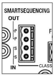
SMART SEQUENCING—4 Pin Phoenix-Type
The SmartSequencing Barrier Strip is used to connect and daisy-chain other SmartSequencing units together. SmartSequencing requires that a pair of wires be connected between the Primary OUT terminals of one sequencer to the Secondary IN terminals of a second sequencer. The recommended wire is 22AWG but SmartSequencing is extremely tolerant of wire gauge.
FORCE OFF (2) - 2 Pin Phoenix-Type
The FORCE OFF input provides terminals for initiating an immediate shutdown of all SmartLink devices in a SmartLink chain. Fire alarms and other safety devices can be connected to the FORCE OFF input. When activated, the system will begin an immediate, but orderly shutdown starting with the last sequencer in the chain first.

Pin # Description
1 FORCE OFF Input – dry contact active state defined by DIP #4
2 FORCE OFF Input common
Remote Port - 5 Pin Phoenix-Type
The Remote Port Barrier strip is provided to allow Furman Legacy devices to be interoperable with the Miniport. One or more remote location switches can be connected to the Miniport. The switch or switches used may be either a momentary or maintained-contact type. In the most basic configuration, only two wires and an SPST switch are needed to initiate a remote ON or OFF sequence. If a four-conductor cable is used, an LED may be installed between the STAT and GND pins to indicate when the power outlets are on.
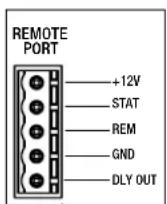
| Pin # Label Description | |
| 1 +12VDC General purpose output 10mA Max | |
| 2 STAT Status output, intended to drive anode of LED | |
| 3 REM Remote control input, behavior defined by DIP 5,6,7 | |
| 4 GND General purpose ground 10mA Max | |
| 5 DLY OUT Delayed output, for connecting downstream devices |
Setup and Troubleshooting
As discussed at the introduction, in order to prevent expensive repairs to speaker enclosures, a power sequencer or multiple power sequencers are employed to coordinate the activation of power within an A/V system. The amplifiers receive AC power last when a system is turned on and amplifiers have the AC power cut before the signal processing is turned off. There are many applications besides those pro audio applications discussed here and SmartSequencing opens up many possibilities. We cover the basics within our documentation, yet this does not mean that other applications cannot garner the benefits of SmartSequencing. Security and IT professionals can also benefit from remote power management and power sequencing. Please feel free to consult a Furman professional to answer any questions or to address the needs for any particular installation.
Single Unit Set Up
Basic installation of the Miniport is ready right out of the box. The default DIP Switch settings should be appropriate for a single stand-alone installation.
Multiple Unit Set Up
If you plan to use the Miniport as a Secondary device within a chain of sequencers, the Miniport will need to be changed from Primary to Secondary status. This is done by changing the setting of DIP switch #8 from ON to OFF and then cycling power.
If you are using several Miniports to control an AV system it is recommended that you connect the signal processing equipment to the Miniports near the beginning of the chain, and the Amplifiers to the sequencers nearest the end of the chain. This will ensure that the power to the signal processing equipment will be active and have had the opportunity to stabilize before power to the amplifiers is activated.
Breaker Overload
The overall current capacity is 15Amps for the CN-15MP and 20Amps for the CN-20MP. This refers to the combined steady-state current drawn by all devices plugged into the power outlets. If the combined current level exceeds the current capacity at any time, the circuit breaker will trip, cutting off power to the connected equipment. If this occurs, the operator must reduce the load by unplugging one or more devices.
Although 15 Amps is an absolute limit, the CN-15MP will allow the operator to come as close as possible to using the full 15 Amps. Power sequencing greatly reduces the risk of tripping the breaker because power sequencing offsets large but temporary inrush currents by activating equipment in stages, rather than simultaneously. This allows each stage to settle to its steady-state current draw before the next stage is powered. If for any reason, reasonable efforts are made to resolve breaker trips and trips continue, please to do not hesitate to contact Furman technical support.
Re-syncing Multiple Sequencers
There can be unique situations where multiple sequencers fall out of sync. For example, loss of sync can occur when a branch circuit experiences an overload or high voltage and triggers an EVS shutdown of one or more units. If you are using a rack mounted Contractor unit equipped with SmartSequencing, you can re-establish sync by pressing and holding the Start Sequence pushbutton on the Primary Unit for several seconds. Sync can also be re-established by rotating the key on the primary unit from the REMOTE to the OFF position and then back to REMOTE. When pressing and holding the pushbutton on dedicated SmartSequencing units, the Primary Unit commands the Secondary Units to "Go Home" and all units will sequence down in reverse order. Once the chain of sequencers has cycled off, the sequencers can be sequenced on again by pressing the START SEQUENCE button or turning the key switch to the ON position.
Legacy connected sequencers can also be re-synced if the sequencers are operating Momentary Mode. The units will resync can be accomplished by pressing and holding the Start Sequence pushbutton. Unlike the SmartSequencing chains, units will cycle down, yet may not cycle down in hierarchical order. It is advised that all sound sources be muted before a re-sync action is initiated. Once the re-sync is initiated, unit will cycle down and return to an off state. A sequence can now be “ramped up” in order.
SPECIFICATIONS
Maximum AC Current Rating:
• CN-15MP - 15 Amps, 120 VAC (Thermal circuit breaker)
• CN-20MP - 20 Amps, 120 VAC (No circuit breaker)
AC Cord:
• 3/14 AWG, 10 feet, black, fixed, NEMA 5-15P plug
AC Receptacles:
• AC Outlets: 2 Switched NEMA 5-15R (1 duplex)
Surge/Under-Overvoltage Protection:
• AC Undervoltage Protection: EVS, 77VAC+/-3VAC
• AC Overvoltage Protection: EVS, 145VAC+/-5VAC
- AC EVS Protection Activate/Deactivate Modes: ON or OFF DIP 9 (configurable)
Operating Temperature Range:
- 5C (40F) to 40C (105F) degrees
Humidity Range:
- < 90% rH (Relative Humidity)
User Interface:
• Thermal Circuit Breaker: Bottom panel, pushbutton (CN-15MP only)
- Front panel diagnostic indicators: Primary link, Secondary link, Power, Extreme Voltage
- Side Panel DIP Switches: Hidden by security cover, 1 Minute Delay, 2 Minute Delay, 4 Minute Delay, Force Off NO/NC, 12V Mode ON/OFF, GND Mode On, Momentary/Maintained, Primary/Secondary, EVS ON/OFF
- Potentiometer: Side panel, time calibration hidden by security cover, fine tune delay adjust
Control/Status/Triggering (Front Panel):
- Remote Terminal: +5-30VDC IN, 12VDC (12mA) OUT
- SmartSequencing: Phoenix type 4-Pin Connector, with Screw Terminals, Primary & Secondary Links (Current Loop - 1000' maximum)
- Remote Terminal: Phoenix type 5-Pin Connector with Screw Terminals; +12V, STAT, REM, GND, DLY OUT (Class 2 Wiring)
- Force Off: Phoenix type 2-Pin Connector with Screw Terminals, (Class 2 Wiring)
Power Consumption (No Load): 10 Watts
Safety Agency: NRTL-C CSA/NRTL Compliant:
Specifications subject to change due to product upgrades and improvements.
15 YEAR LIMITED PRODUCT WARRANTY*
Furman warrants to the original purchaser of this product for a period of fifteen (15) years from the date of purchase, that the unit shall be free of defects in design, material or workmanship, and Furman will repair or replace any defective unit.
Full Warranty and Policy information available at www.furmancontractor.com
CAUTION! WARRANTY LIMITATION FOR INTERNET PURCHASERS
Furman products purchased through the Internet do not carry a valid Product Warranty unless purchased from an Authorized Furman Internet Dealer and the original factory serial numbers are intact (they must not have been removed, defaced or replaced in any way). Purchasing from an Authorized Furman Internet Dealer insures that the product was intended for consumer use, has passed all quality inspections and is safe. Buying through auction sites or unauthorized dealers may result in the purchase of salvaged, failed and/or products not intended for use in the US. In addition, Authorized Furman Internet dealers have demonstrated sufficient expertise to insure warranty compliant installations.
For a list of Authorized Furman Internet Dealers
go to www.furmansound.com
- CONTRACTOR SERIES SMARTSEQUENCER™
- MINIPORT CN-15MP AND CN-20MP INSTRUCTIONS
- FEATURES
- INTRODUCTION
- WHY CHOOSE FURMAN
- WHY CHOOSE AC POWER SEQUENCING
- BEFORE YOU BEGIN INSPECT UPON RECEIPT
- TABLE OF CONTENTS
- SMARTSEQUENCING™
- EVS (EXTREME VOLTAGE SHUTDOWN)
- REMOTE ACCESS (AND BLUEBOLT®)
- SECURITY AND SAFETY
- ADDITIONAL FEATURES
- IMPORTANT SAFETY INSTRUCTIONS
- ABBREVIATED PRODUCT FEATURES
- SMARTSEQUENCING™ 101
- SIDE PANEL OVERVIEW
- BYPASS SWITCH
- DIP SWITCH AND DELAY ADJUSTMENT
- DIP 1, 2, & 3 AND THE DELAY ADJUSTMENT
- DELAY ADJUSTMENT
- DIP 4 FORCE OFF SETTING
- DIP 5 AND 6 REMOTE INPUT SETTING
- DIP 8 PRIMARY / SECONDARY SETTING
- DIP 9 EVS ON OR EVS OFF SETTING
- CONNECTION STATUS LIGHTS
- POWER INDICATOR
- EVS LED
- CIRCUIT BREAKER
- CN-15MP
- CN-20MP
- TERMINAL BARRIER STRIPS
- SMART SEQUENCING—4 PIN PHOENIX-TYPE
- FORCE OFF (2) - 2 PIN PHOENIX-TYPE
- PIN # DESCRIPTION
- REMOTE PORT - 5 PIN PHOENIX-TYPE
- SETUP AND TROUBLESHOOTING
- SINGLE UNIT SET UP
- MULTIPLE UNIT SET UP
- BREAKER OVERLOAD
- RE-SYNCING MULTIPLE SEQUENCERS
- SPECIFICATIONS
- MAXIMUM AC CURRENT RATING
- AC CORD
- AC RECEPTACLES
- SURGE/UNDER-OVERVOLTAGE PROTECTION
- OPERATING TEMPERATURE RANGE
- HUMIDITY RANGE
- USER INTERFACE
- CONTROL/STATUS/TRIGGERING (FRONT PANEL)
- 15 YEAR LIMITED PRODUCT WARRANTY
- CAUTION! WARRANTY LIMITATION FOR INTERNET PURCHASERS
Brand : Furman
Model : SmartSequencers CN-20MP
Category : Power Regulator