
MEI 1000 G2 - Earplug LD Systems - Free user manual and instructions
Find the device manual for free MEI 1000 G2 LD Systems in PDF.

| Brand | LD Systems |
| Model | MEI 1000 G2 |
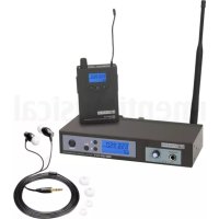
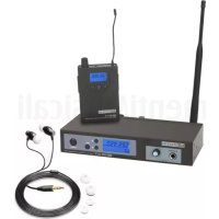
| Product type | Wireless In-Ear Monitoring System |
| RF frequency range | 823 - 832 MHz, 863 - 865 MHz |
| Number of channels | 96 (8 groups of 12 channels) |
| RF link type | FM, stereo |
| Frequency response | 60 Hz - 16 kHz |
| Signal-to-noise ratio (transmitter) | 85 dB |
| Signal-to-noise ratio (receiver) | 80 dB |
| Distortion rate (THD) | < 1% |
| RF output power (transmitter) | 10 mW |
| Audio output (receiver) | 3.5 mm stereo mini-jack, 100 mW |
| Power supply (transmitter) | 12 - 18 V DC (power supply unit included) |
| Power supply (receiver) | 2 LR06 (AA) batteries, battery life > 12 h |
| Dimensions (transmitter) | 200 x 44 x 96 mm |
| Weight (transmitter) | 1.2 kg |
| Dimensions (receiver) | 65 x 90 x 24 mm |
| Weight (receiver) | 0.1 kg (without batteries) |
| Included accessories | User manual, power supply unit, antenna, in-ear headphones, 19" rack mount kit, ABS transport case |
| Operating modes | Mono, Stereo, Focus |
| Special functions | Equalizer (EQ), Limiter, Lock, Balance/Focus adjustment |
| Safety | Protection against high sound levels, warning for mains powered devices |
| Maintenance and cleaning | Clean with a dry cloth |
| Reparability | Repair only by qualified technical personnel |
| Manufacturer's warranty | 2 to 5 years depending on product (see conditions) |
Frequently Asked Questions - MEI 1000 G2 LD Systems
User questions about MEI 1000 G2 LD Systems
0 question about this device. Answer the ones you know or ask your own.
Ask a new question about this device
Download the instructions for your Earplug in PDF format for free! Find your manual MEI 1000 G2 - LD Systems and take your electronic device back in hand. On this page are published all the documents necessary for the use of your device. MEI 1000 G2 by LD Systems.
USER MANUAL MEI 1000 G2 LD Systems
You've made the right choice!
We have designed this product to operate reliably over many years. LD Systems stands for this with its name and many years of experience as a manufacturer of high-quality audio products.
Please read this User's Manual carefully, so that you can begin making optimum use of your LD Systems product quickly.
You can find more information about LD SYSTEMS at our Internet site WWW.LD-SYSTEMS.COM
Introduction
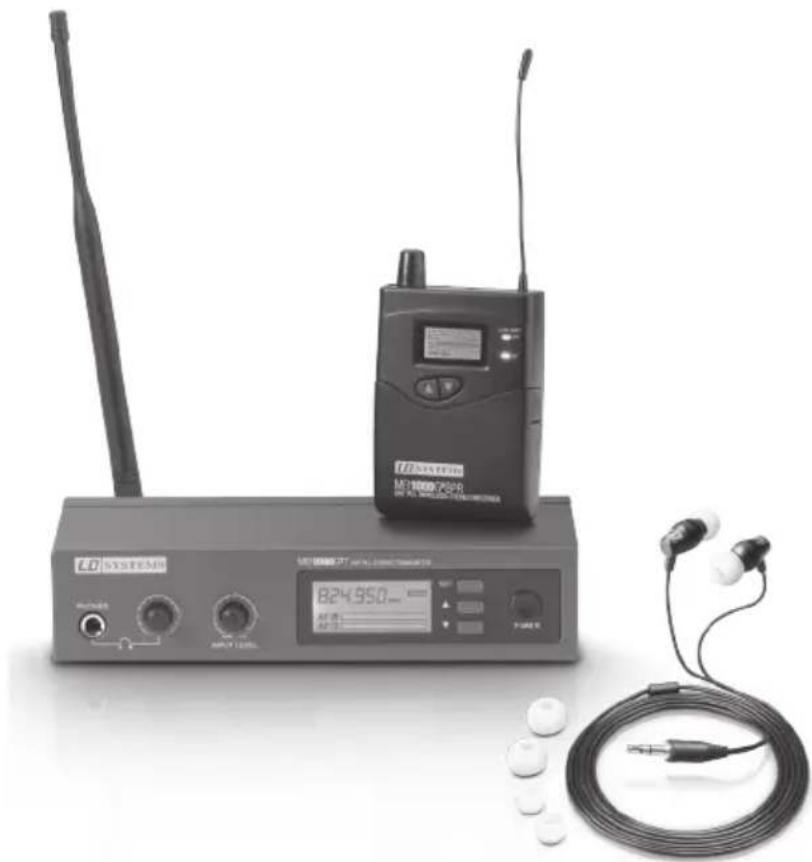
The new LD Systems MEI1000G2 is an In-Ear Monitoring-System with 96 UHF channels that delivers natural sound with a large dynamic range and outstanding crosstalk behaviour in the 823 - 832 and 863 - 865 MHz frequency bands.
Switchable mono, stereo, and focus monitoring modes as well as adjustable EQ and limiter functions permit natural sound reproduction for any application, with a frequency response of 60Hz - 16Hz , a high S/N ratio, and low THD. The LD MEI1000G2 allows for the simultaneous operation of up to 5 systems.
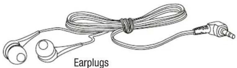
The earphones are very comfortable to wear, and the multifunctional display on the receiver shows all relevant system information. With high quality batteries, it is possible to attain operating times of 12 hours and more. The MEI100G2 package includes a 19^ rackmount kit and a rugged carrying case made of ABS plastic.
LDME1000G²
WIRELESS IN EAR MONITORING SYSTEM
PREVENTIVE MEASURES:
- Please read these instructions carefully.
- Keep all information and instructions in a safe place.
- Follow the instructions.
- Observe all safety warnings. Never remove safety warnings or other information from the equipment.
- Use the equipment only in the intended manner and for the intended purpose.
- Use only sufficiently stable and compatible stands and/or mounts (for fixed installations). Make certain that wall mounts are properly installed and secured. Make certain that the equipment is installed securely and cannot fall down.
- During installation, observe the applicable safety regulations for your country.
- Never install and operate the equipment near radiators, heat registers, ovens or other sources of heat. Make certain that the equipment is always installed so that is cooled sufficiently and cannot overheat.
- Never place sources of ignition, e.g., burning candles, on the equipment.
- Ventilation slits must not be blocked.
- Do not use this equipment in the immediate vicinity of water (does not apply to special outdoor equipment - in this case, observe the special instructions noted below. Do not expose this equipment to flammable materials, fluids or gases.
- Make certain that dripping or splashed water cannot enter the equipment. Do not place containers filled with liquids, such as vases or drinking vessels, on the equipment.
- Make certain that objects cannot fall into the device.
- Use this equipment only with the accessories recommended and intended by the manufacturer.
- Do not open or modify this equipment.
- After connecting the equipment, check all cables in order to prevent damage or accidents, e.g., due to tripping hazards.
- During transport, make certain that the equipment cannot fall down and possibly cause property damage and personal injuries.
- If your equipment is no longer functioning properly, if fluids or objects have gotten inside the equipment or if it has been damaged in anot her way, switch it off immediately and unplug it from the mains outlet (if it is a powered device). This equipment may only be repaired by authorized, qualified personnel.
- Clean the equipment using a dry cloth.
- Comply with all applicable disposal laws in your country. During disposal of packaging, please separate plastic and paper/cardboard.
- Plastic bags must be kept out of reach of children.
FOR EQUIPMENT That Connects to THE POWER malns:
- CAUTION: If the power cord of the device is equipped with an earthing contact, then it must be connected to an outlet with a protective ground. Never deactivate the protective ground of a power cord.
- If the equipment has been exposed to strong fluctuations in temperature (for example, after transport), do not switch it on immediately. Moisture and condensation could damage the equipment. Do not switch on the equipment until it has reached room temperature.
- Before connecting the equipment to the power outlet, first verify that the mains voltage and frequency match the values specified on the equipment. If the equipment has a voltage selection switch, connect the equipment to the power outlet only if the equipment values and the mains power values match. If the included power cord or power adapter does not fit in your wall outlet, contact your electrician.
- Do not step on the power cord. Make certain that the power cable does not become kinked, especially at the mains outlet and/or power adapter and the equipment connector.
- When connecting the equipment, make certain that the power cord or power adapter is always freely accessible. Always disconnect the equipment from the power supply if the equipment is not in use or if you want
SAFETY:
to clean the equipment. Always unplug the power cord and power adapter from the power outlet at the plug or adapter and not by pulling on the cord. Never touch the power cord and power adapter with wet hands.
- Whenever possible, avoid switching the equipment on and off in quick succession because otherwise this can shorten the useful life of the equipment.
- IMPORTANT INFORMATION: Replace fuses only with fuses of the same type and rating. If a fuse blows repeatedly, please contact an authorised service centre.
- To disconnect the equipment from the power mains completely, unplug the power cord or power adapter from the power outlet.
- If your device is equipped with a Volex power connector, the mating Volex equipment connector must be unlocked before it can be removed. However, this also means that the equipment can slide and fall down if the power cable is pulled, which can lead to personal injuries and/or other damage. For this reason, always be careful when laying cables.
- Unplug the power cord and power adapter from the power outlet if there is a risk of a lightning strike or before extended periods of disuse.

CAUTION:
Never remove the cover, because otherwise there may be a risk of electric shock. There are no user serviceable parts inside. Have repairs carried out only by qualified service personnel.
The lightning flash with arrowhead symbol within an equilateral triangle is intended to alert the user to the presence of uninsulated "dangerous voltage" within the product's enclosure that may be of sufficient magnitude to constitute a risk of electrical shock.

The exclamation mark within an equilateral triangle is intended to alert the user to the presence of important operating and maintenance instructions.
CAUTION - HIGH VOLUME LEVELS WITH AUDIO PRODUCTS!
This equipment is intended for professional use. Therefore, commercial use of this equipment is subject to the respectively applicable national accident prevention rules and regulations. As a manufacturer, Adam Hall is obligated to notify you formally about the existence of potential health risks.
Hearing damage due to high volume and prolonged exposure: When in use, this product is capable of producing high sound-pressure levels (SPL) that can lead to irreversible hearing damage in performers, employees, and audience members. For this reason, avoid prolonged exposure to volumes in excess of 90 dB.
CAUTION! IMPORTANT INFORMATION ABOUT LIGHTING PRODUCTS
- Do not look into the beam from a distance of less than 40~cm
- Do not stare into the beam for extended periods at short-to-medium distances.
- Do not view the beam directly with optical instruments such as magnifiers.
- Under some circumstances, stroboscopic effects may trigger epileptic seizures in sensitive individuals! For this reason, persons who suffer from epilepsy should always avoid places where strobe lights are used.
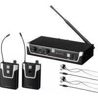
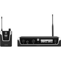
SYSTEM COMPONENTS:
Transmitter
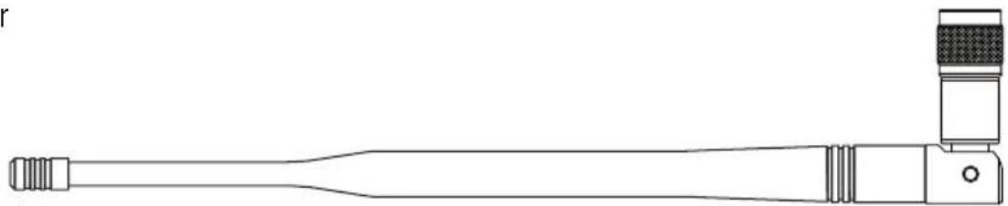
Antenna
Belt pack receiver
2 "AA" batteries
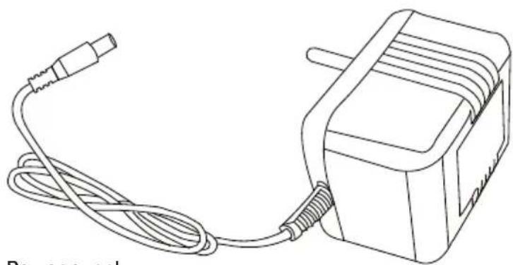
Power supply
CONNECTIONS, CONTROLS, AND INDICATORS:
TRANSMITTER:
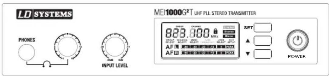
Front Panel
LDSYSTEMS
PHONES


INPUT LEVEL
MEI1000G2TUHFPLLSTEROTRANSMITTER
5
SET 4


POWER
1 POWER-BUTTON
Switch on: Press and hold button for two seconds. Switch off: Press and hold button for two seconds.
2 ARROW DOWN BUTTON
See Chapter "System Setup".
ARROW UP BUTTON
See Chapter "System Setup".
SET(PROGRAMMINGBUTTON)
See Chapter "System Setup".
LC DISPLAY
Backlit LC Display. See Chapter "System Setup".
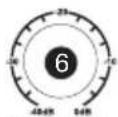
INPUT LEVEL
Adjust the input sensitivity. In order to achieve an optimal signal to noise ratio, bring the input signal as close as possible to the 0dB indicator (level indicator AF L and AF R in the display), without exceeding the distortion limit (PEAK segment in the level meter).
HEADPHONE VOLUME CONTROL
Turning the knob to the left decreases the volume; turning it to the right increases the volume. To avoid hearing damage, set the volume to minimum before using the earphones/headphones, then slowly increase the volume. Caution: high volume can cause permanent hearing damage.
8 PHONES
Headphone output connector 6.3 mm stereo jack.
CONNECTIONS, CONTROLS, AND INDICATORS:
TRANSMITTER:
Rear panel
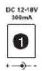

LOW VOLTAGE CONNECTOR
Power supply connector for 12 - 18V DC (included).
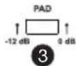
Switchable level attenuation for high input level.
Switch in position -12 dB: Attenuation of the input signal by 12 db
Switch in position 0 dB: No attenuation of the input signal.
4 ANTENNA
TNC antenna connector 50 Ohm.
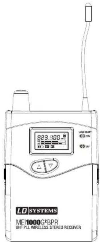
BELT PACK RECEIVER
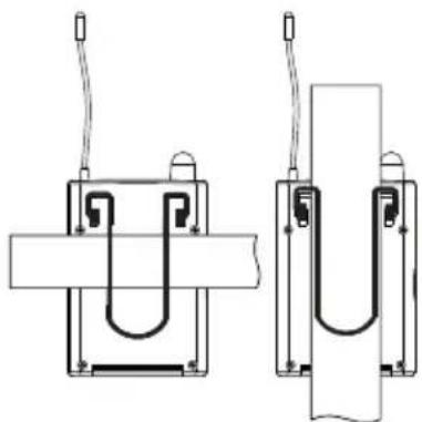
BELTCLIP
Clip the receiver to your belt or a suitable strap. For optimum fit, the clip should always be pushed all the way over the belt and/or strap (see illustration).
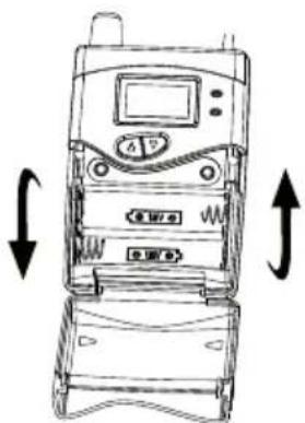
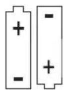
Battery replacement
To replace the batteries, press gently on the marked spots on the sides of the battery cover and flip it forward. Remove the batteries, insert two new AA-batteries (for orientation please see the illustration in the battery compartment) and close the cover. Remove the batteries when the device is not in use for an extended period.
CONNECTIONS, CONTROLS, AND INDICATORS:
BELT PACK RECEIVER:
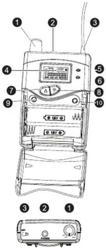
4 LC DISPLAY
Backlit LC Display. The back light automatically turns off after about 30 seconds if no control buttons are pressed; the back light is turned on when any of the control buttons is selected. See Chapter "System Setup".
LOW BATT LED
LED lights when the battery charge is low. Please replace the batteries as soon as possible.
RF SIGNAL LED
Lights up briefly when you switch on. Lights up when a HF signal is present. Radio frequency of both transmitter and receiver must match.
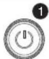
ON/OFF - VOLUME
On / Off switch and volume control. To switch on, turn the knob to the right (clockwise) past the snap-in point. To switch off, turn the knob to the left (counter clockwise) past the snap-in point. Turning the knob to the left decreases the volume; turning it to the right increases the volume. To avoid hearing damage, set the volume to minimum before using the earphones/headphones, then slowly increase the volume. Caution: high volume can cause permanent hearing damage.
2 PHONES
Earphone/headphone connector 3.5mm stereo jack.
3 ANTENNA
7 ARROW UP BUTTON
See Chapter "System Setup".
ARROW DOWN BUTTON
See Chapter "System Setup".
9 ESC-BU TTON
Press this button to return to the main menu.
10 SET BUTTON
See Chapter "System Setup".
SYSTEM SETUP:
1
2
3
4
5
TRANSMITTER PROGRAMMING:
MAIN MENU
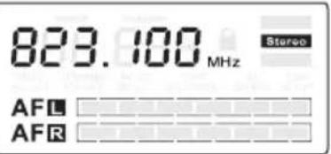
In the main menu the radio frequency, the operating mode (mono/ stereo) and signal level (AF L and AF R) are displayed.
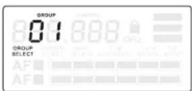
2 SELECTING A FREQUENCY GROUP 1 - 8
Press the SET button repeatedly until "GROUP SELECT" appears in the display. Press the keys select the desired frequency group.
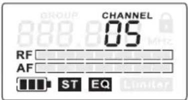
SELECTING A CHANNEL 1 - 12
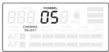
Press the SET button repeatedly until "CHANNEL SELECT" appears in the display. Press the keys to select the desired channel.
Note: For simultaneous operation of several systems, please make sure that all the systems use different channels on the same frequency group.
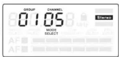
Press the SET button repeatedly until "MODE SELECT" appears in the display.
With the buttons, you can now choose between mono and stereo mode.
Select the mono mode if only one (mono) audio signal is to be transmitted to the receiver. The signal is located on two channels (left/right) of the receiver. In the mono mode, only the right input (INPUT RIGHT) may be used.
Select the stereo mode if either a stereo signal, or two mono signals are to be transmitted to the receiver.
Please refer to the notes in the Stereo and Focus Mode chapter.
LOCK AGAINST INADVERTENT CHANGES
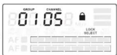
Press the SET button repeatedly until "LOCK SELECT" appears in the display. Press the keys lock or unlock the system. If "LOCK SELECT is enabled, the system settings can be viewed, but not changed.
EXIT THE SETUP MENU
Press the SET button repeatedly until "EXIT SETUP" appears in the display. Press the keys exit the menu. If no control buttons are pressed, the display switches automatically to the main menu after a few seconds.
SYSTEM SETUP:
1
RECEIVER PROGRAMMING:
To change settings on the receiver, press gently on the marked spots on the sides of the battery cover and flip it forward. The Escape (ESC) and SET buttons are now accessible. To return to the main menu after a setting change, press the Escape button (ESC).
2
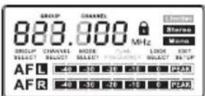
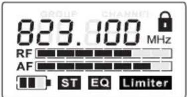
1 MAIN MENU
In the main menu, the radio frequency, RF and AF level, mono / stereo mode, EQ, limiter, as well as the lock status are displayed.
3
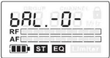
BALANCE
Adjust the volume balance between the left and right channels of a stereo signal using the buttons. When the transmitter is in mono mode, using the buttons will set the position of the signal in the panoramic field.
4
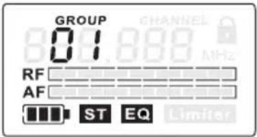
3 SELECTING A FREQUENCY GROUP 1 - 8
Press the SET button repeatedly on the receiver until "GROUP" appears and starts to flash. Press the keys to select the desired frequency group.
5
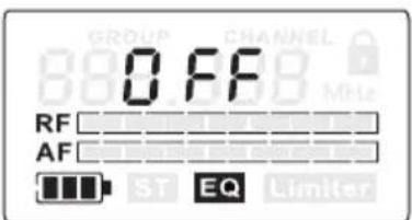
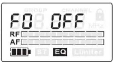
5 EQUALIZER
Press the SET button repeatedly until "EQ" appears in the display and flashes. Use the buttons to determine whether the Equalizer should be enabled (EQ ON), or disabled (EQ OFF). When the EQ is enabled, the treble at 10kHz is increased by around 6dB.
SYSTEM SETUP:
6
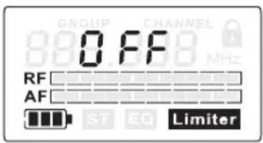
LIMITER
Press the SET button repeatedly until "LIMITER" appears in the display and flashes. Using the button, you can enable (Limiter ON) or disable (limiter OFF) the limiter.
7
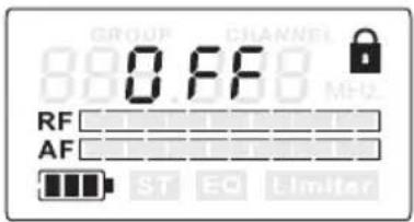
Press the SET button repeatedly until the lock symbol appears in the display. Press the button to lock (ON) or release (OFF) the receiver. If the receiver is locked, the settings can be viewed, but not changed.
8
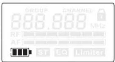
BATTERY CHARGE STATUS
The charge status of the batteries is shown in four stages. In addition to the fourth stage (no bars on the battery symbol) the red LOW BATT LED will light up next to the display. The batteries should now be replaced immediately.
7
8
SYSTEM SETUP:
1
RECEIVER PROGRAMMING:
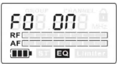
1+2STEREO MODE
Select the stereo mode for the transmission of a stereophonic audio signal.
Press the SET button repeatedly until "FO OFF" or "FO ON" appears in the display and flashes. Using the buttons, you can now activate the stereo mode (FO OFF).
In stereo mode, the two input signals of the transmitter can be heard through headphones (on the left and right) connected to the receiver
On the receiver, the balance between the two input signals can be set with the help of the buttons. A total of 31 levels are available: using the button, the centre location of a stereo signal can be changed by 15 levels to the right
(1-, 2-, 3-, 4-, 5-, 6-, 7-, 8-, 9-, A-, b-, C-, d-, E-, F- and by 15 levels to the left (-1, -2, -3, -4, -5, -6, -7, -8, -9, -A, -b, -C, -d, -E, -F). To bring the centre location of a stereophonic audio signal to the centre of the stereo base, please select the -0- setting. To ensure the transmission of a stereo audio signal in the stereo mode, both the transmitter and the receiver have to be in stereo mode and an audio signal has to be present at the INPUT LEFT and RIGHT entrances. When the transmitter is in mono mode, only the audio signal (INPUT RIGHT) is being transferred.
SYSTEM SETUP:
3
4
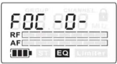
3 + 4 FOCUS MODE (ALSO KNOWN AS "DUAL MONO")
Select the Focus mode in order to listen to two mono signals in the centre of the panoramic field, and to customize their volume. Example Rock Band (user is the lead singer): the first mono audio signal comprises a mix of drums, bass and guitar (the mixer is fed by a monitor signal 1). The second mono audio signal contains the microphone signal of the singer (the mixer is fed by monitor signal 2). The singer can now directly adjust the volume balance between the instruments and his voice and the overall volume level.
Press the SET button repeatedly until "FO OFF" or "FO ON" appears in the display and flashes. Using the buttons, you can now activate the Focus mode (FO ON). In Focus mode the two input signals of the transmitter are mixed together and played back in mono. The user can now directly adjust the volume balance of the signals by up to 31 levels with the help of the buttons on the receiver To push the mono signal of the transmitter (INPUT RIGHT) into the background, use the button levels: FOC 1-, 2-, 3-, 4-, 5-, 6-, 7-, 8-, 9-, A-, b-, C-, d-, E-, max. F-). The volume balance is changed in favour of the audio signal at the left input (INPUT LEFT) of the transmitter.
To push the mono signal of the transmitter (INPUT LEFT) into the background, use the button 15 levels: FOC -1, -2, -3, -4, -5, -6, -7, -8, -9, -A, -b, -C, -d, -E, a max. -F). The volume balance is changed in favour of the audio signal at the right input (INPUT RIGHT) of the transmitter. In the FOC -0- setting, both input signals of the transmitter are transmitted at the same volume.
To ensure the transmission of a stereo audio signal in the Focus mode, both the transmitter and the receiver have to be in stereo mode and an audio signal must be present at both INPUT LEFT and RIGHT entrances. When the transmitter is in mono mode, only the (INPUT RIGHT) audio signal is being transmitted.
SETTING UP AND TROUBLESHOOTING:
SETUP
For optimal transmission, position the transmitter at a minimum height of 1 m and point the antenna upwards. If multiple wireless systems are used in an installation, please make sure that the antennas do not touch or cross. Do not position the transmitter in the direct vicinity of metal objects and digitally controlled devices (CD players, computers, digital consoles, etc.). Transmitter and receiver should be within direct "line of sight" of each other.
TROUBLESHOOTING
| PROBLEM DISPLAY SOLUTION | ||
| No sound or volume too low. | Receiver: Display is switched off. | Make certain that the batteries are not dead and the receiver is on. |
| Transmitter: Display is switched off. | Check the connection between power supply and transmitter. Turn on the transmitter. | |
| Receiver: is on, but the RF indicator is not lit. | Make certain that the transmitter and receiver are set to the same radio frequency. | |
| Reduce the distance between transmitter and receiver and make certain that there is a direct line of sight between transmitter and receiver. | ||
| Make certain that the transmitter antenna is installed correctly. | ||
| Receiver: is on and the RF indicator is lit. | Increase the volume at the receiver and check the headphone connection. | |
| Check the input level on the transmitter and increase it if necessary. | ||
| Distortion or noise. Receiver: RF indicator is on. | Increase the distance to possible causes of interference (digitally controlled devices, e.g., CD players, computers, digital consoles...). | |
| Use a different radio frequency. | ||
| Distorted sound. | Receiver: LOW BATT LED lights up | Replace the batteries with new ones. |
| Transmitter: Level indicator is too high | Lower the volume at the level controls of the transmitter or at the source device. | |
TROUBLESHOOTING:
| Stereo and Focus mode: Only the right input signal of the transmitter is heard, although the receiver is in the stereo mode and both inputs of the transmitter are used. | Transmitter: The transmitter is in the mono mode. | Switch the transmitter to the stereo mode. |
| A mono signal is to be transmitted, but the signal is only heard on one side of the headphones. | Transmitter: The transmitter is in the stereo mode. | Switch the transmitter to the mono mode. |
| Two mono signals are to be heard centred in the headphones, but are distributed left and right | Switch the receiver to the Focus mode. |
FREQUENCY LIST:
| Group 1 | Group 2 | Group 3 | Group 4 | Group 5 | Group 6 | Group 7 | Group 8 | |||
| Channel 1 863.100 | 863.100 | 863.100 | 863.200 | 863.150 | 863.150 | 863.100 | 863.250 | 863.250 | ||
| Channel 2 863.500 | 863.500 | 863.500 | 863.700 | 863.550 | 863.950 | 863.700 | 863.650 | 863.850 | ||
| Channel 3 864.300 | 864.300 | 864.000 | 864.100 | 864.050 | 864.450 | 864.500 | 864.150 | 864.350 | ||
| Channel 4 864.900 | 864.900 | 864.800 | 864.800 | 864.850 | 864.850 | 864.900 | 864.750 | 864.750 | ||
| Channel 5 823.100 | 823.100 | 823.100 | 823.200 | 823.150 | 823.100 | 823.100 | 823.150 | 823.250 | ||
| Channel 6 823.500 | 823.500 | 823.700 | 823.800 | 823.750 | 823.700 | 823.600 | 823.850 | 823.950 | ||
| Channel 7 824.100 | 824.100 | 824.700 | 824.600 | 824.750 | 824.700 | 824.600 | 824.850 | 824.950 | ||
| Channel 8 825.500 | 825.500 | 825.800 | 825.600 | 825.850 | 825.800 | 825.300 | 825.650 | 825.750 | ||
| Channel 9 826.300 | 826.300 | 826.500 | 826.800 | 826.550 | 826.500 | 826.200 | 826.850 | 826.950 | ||
| Channel 10 828.900 | 828.900 | 827.700 | 828.100 | 827.750 | 827.700 | 827.300 | 828.250 | 828.350 | ||
| Channel 11 830.100 | 830.100 | 829.100 | 829.600 | 829.150 | 829.100 | 829.200 | 829.550 | 829.650 | ||
| Channel 12 831.900 | 831.900 | 830.600 | 831.300 | 831.650 | 830.600 | 831.600 | 831.150 | 831.250 |
SPECIFICATIONS:
| Model name: LDMEI1000G2 | |
| Product type In-Ear Monitoring Set | |
| Radio frequency range 823 - 832 MHz, 863 - 865 MHz | |
| Weight 1,3 kg | |
| LDME1000G2BPR | |
| Product type Belt pack receiver | |
| Channels: 96 (8 groups of 12 channels) | |
| Transmission technology FM, stereo | |
| Frequency range 60 Hz - 16000 Hz | |
| S/N ratio 80 dB | |
| Total Harmonic Distortion (THD) | < 1% |
| Audio outputs: | 3.5 mm stereo jack |
| Max. audio output level: | 100 mW |
| Controls | Up, Down, Set, Volume, Escape |
| Indicators | LC-Display, Low Battery, RF |
| Power supply | 2 x 1.5 V AA |
| Operating time: | > 12 hrs., battery-dependent |
| Width | 65 mm |
| Height | 90 mm |
| Depth | 24 mm |
| Weight 0,1 kg (without batteries) | |
SPECIFICATIONS:
| LDME1000G2T | |
| Product type Transmitter | |
| Channels: 96 (8 groups of 12 channels) | |
| Transmission technology FM, stereo | |
| HF output power 10 mW | |
| Frequency range 60 Hz - 16000 Hz | |
| S/N ratio 85 dB | |
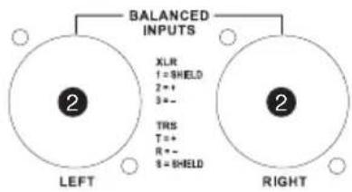
| Inputs 2 | |
| Input connections: 6.3 mm TRS, XLR | |
| Input impedance (kOhm) 14 kOhm | |
| Antenna connector | TNC |
| Controls | Input Level, Power, Up, Down, Pad, Set, Volume Headphone |
| Indicators | LC display |
| Power supply | 12 - 18 V DC |
| Width | 200 mm |
| Height | 44 mm |
| Depth | 96 mm |
| Weight | 1,2 kg |
| Accessories (included) | User manual, power supply, antenna, headphones, rack mount kit |
MANUFACTURER'S DECLARATIONS:
MANUFACTURER'S WARRANTY
This warranty covers the Adam Hall, LD Systems, Defender, Palmer, and Cameo brands.
It applies to all products distributed by Adam Hall.
This warranty declaration does not affect the statutory warranty claims against the manufacturer, but expands them with additional warranty claims vis-a-vis Adam Hall.
Adam Hall warrants that the Adam Hall product that you have purchased from Adam Hall or from an Adam Hall authorized reseller is free from defects in materials or workmanship under normal use for a period of 2 or 5 years (please inquire on a product-by-product basis) from the date of purchase.
The warranty period begins on the date on which the product was purchased, proof of which must be produced (through presentation of the invoice or the delivery note with the date of purchase) in the event of a warranty claim. Should products of the brands named above be in need of repair within the limited warranty period, you are entitled to warranty service according to the terms and conditions stated here.
During the Limited Warranty Period, Adam Hall will repair or replace the defective component parts or the product. In the event of repair or replacement during the Limited Warranty Period, the replaced original parts and/or products become property of Adam Hall.
In the unlikely event that the product which you purchased has a recurring failure, Adam Hall has the right, at its discretion, to replace the defective product with another product, provided that the new product is at least equivalent to the product being replaced with regard to the technical specifications.
Adam Hall does not warrant that the operation of this product will be uninterrupted or error-free. Adam Hall is not responsible for damage that occurs as a result of your failure to follow the instructions included with the Adam Hall branded product. The manufacturer's warranty does not cover - expendable parts (e.g., rechargeable batteries) - products from which the serial number has been removed or with a serial number that has been damaged as a result of an accident - damage due to improper use, user error or other external reasons
- damage to devices operated outside the usage parameters stated in the documentation included with the product
- damage due to the use of replacement parts not manufactured, sold or recommended by Adam Hall,
- damage due to modification or servicing by anyone other than Adam Hall.
These terms and conditions constitute the complete and exclusive warranty agreement between you and Adam Hall regarding the Adam Hall branded product you have purchased.
MANUFACTURER'S DECLARATIONS:
LIMITATION OF LIABILITY
If your Adam Hall branded hardware product fails to work as warranted above, your sole and exclusive remedy shall be repair or replacement. Adam Halls' maximum liability under this limited warranty is expressly limited to the lesser of the price you have paid for the product or the cost of repair or replacement of any components that malfunction under conditions of normal use.
Adam Hall is not liable for any damages caused by the product or the failure of the product, including any lost profits or savings or special, incidental, or consequential damages. Adam Hall is not liable for any claim made by a third party or made by you for a third party.
This limitation of liability applies whether damages are sought, or claims are made, under this Limited Warranty or as a tort claim (including negligence and strict product liability), a contract claim, or any other claim, and cannot be rescinded or changed by anyone. This limitation of liability will be effective even if you have advised Adam Hall or an authorized representative of Adam Hall of the possibility of any such damages, but not, however, in the event of claims for damages in connection with personal injuries.
This manufacturer's warranty grants you specific rights; depending on jurisdiction (nation or state), you may be entitled to additional claims. You are advised to consult applicable state or national laws for a full determination of your rights.
REQUESTING WARRANTY SERVICE
To request warranty service for the product, contact Adam Hall or the Adam Hall authorized reseller from which you purchased the product.
EC DECLARATION OF CONFORMITY
The equipment marketed by Adam Hall complies (where applicable) with the essential requirements and other relevant specifications of Directives 1999/5/EC (R&TTE), 2004/108/EC (EMC) und 2006/95/EC (LVD). Additional information can be found at www.adamhall.com.
MANUFACTURER'S DECLARATIONS:
PROPER DISPOSAL OF THIS PRODUCT

(Valid in the European Union and other European countries with waste separation)
This symbol on the product, or the documents accompanying the product, indicates that this appliance may not be treated as household waste. This is to avoid environmental damage or personal injury due to uncontrolled waste disposal. Please dispose of this product separately from other waste and have it recycled to promote sustainable economic activity.
Household users should contact either the retailer where they purchased this product, or their local government office, for details on where and how they can recycle this item in an environmentally friendly manner. Business users should contact their supplier and check the terms and conditions of the purchase contract. This product should not be mixed with other commercial wastes for disposal.
ENVIRONMENTAL PROTECTION AND ENERGY CONSERVATION
Energy conservation is an active contribution to environmental protection. Please turn off all unneeded electrical devices. To prevent unneeded devices from consuming power in standby mode, disconnect the mains plug.
Adam Hall GmbH, all rights reserved. The technical data and the functional product characteristics can be subject to modifications. The photocopying, the translation, and all other forms of copying of fragments or of the integrity of this user's manual is prohibited.
3 + 4 MODE FOCUS (OU "DOUBLE MONO")
MISE AU REBUT DE CE PRODUIT
GWARANCJA PRODUCENTA
DEKLARACJA ZGODNOSCI WE

- You've made the right choice!
- Introduction
- LDME1000G²
- PREVENTIVE MEASURES:
- FOR EQUIPMENT That Connects to THE POWER malns:
- SAFETY:
- CAUTION:
- CAUTION - HIGH VOLUME LEVELS WITH AUDIO PRODUCTS!
- CAUTION! IMPORTANT INFORMATION ABOUT LIGHTING PRODUCTS
- SYSTEM COMPONENTS:
- CONNECTIONS, CONTROLS, AND INDICATORS:
- TRANSMITTER:
- Front Panel
- Rear panel
- LOW VOLTAGE CONNECTOR
- ANTENNA
- BELT PACK RECEIVER
- BELTCLIP
- Battery replacement
- BELT PACK RECEIVER:
- LC DISPLAY
- LOW BATT LED
- RF SIGNAL LED
- ON/OFF - VOLUME
- PHONES
- ANTENNA
- ARROW UP BUTTON
- ARROW DOWN BUTTON
- ESC-BU TTON
- SET BUTTON
- SYSTEM SETUP:
- 1
- 2
- 3
- 4
- 5
- TRANSMITTER PROGRAMMING:
- MAIN MENU
- SELECTING A FREQUENCY GROUP 1 - 8
- SELECTING A CHANNEL 1 - 12
- LOCK AGAINST INADVERTENT CHANGES
- EXIT THE SETUP MENU
- RECEIVER PROGRAMMING:
- MAIN MENU
- BALANCE
- SELECTING A FREQUENCY GROUP 1 - 8
- EQUALIZER
- LIMITER
- 7
- 8
- BATTERY CHARGE STATUS
- 1+2STEREO MODE
- + 4 FOCUS MODE (ALSO KNOWN AS "DUAL MONO")
- SETTING UP AND TROUBLESHOOTING:
- SETUP
- TROUBLESHOOTING
- TROUBLESHOOTING:
- FREQUENCY LIST:
- SPECIFICATIONS:
- MANUFACTURER'S DECLARATIONS:
- MANUFACTURER'S WARRANTY
- LIMITATION OF LIABILITY
- REQUESTING WARRANTY SERVICE
- EC DECLARATION OF CONFORMITY
- PROPER DISPOSAL OF THIS PRODUCT
- ENVIRONMENTAL PROTECTION AND ENERGY CONSERVATION
- + 4 MODE FOCUS (OU "DOUBLE MONO")
- MISE AU REBUT DE CE PRODUIT
- GWARANCJA PRODUCENTA
- DEKLARACJA ZGODNOSCI WE
Brand : LD Systems
Model : MEI 1000 G2
Category : Earplug