DW621K - Router DEWALT - Free user manual and instructions
Find the device manual for free DW621K DEWALT in PDF.
User questions about DW621K DEWALT
0 question about this device. Answer the ones you know or ask your own.
Ask a new question about this device
Download the instructions for your Router in PDF format for free! Find your manual DW621K - DEWALT and take your electronic device back in hand. On this page are published all the documents necessary for the use of your device. DW621K by DEWALT.
USER MANUAL DW621K DEWALT
DeWALT Industrial Tool Company, P.O. Box 158, 626 Hanover Pike, Hampstead, MD 21074
Printed in Italy (MAY96-1)
Form No. 154716
Copyright © 1996
INSTRUCTION MANUAL
GUIDE D'UTILISATION
IF YOU HAVE ANY QUESTIONS OR COMMENTS ABOUT THIS OR ANY DEWALT TOOL, CALL US TOLL FREE AT: 1-800-4-DEWALT (1-800-433-9258)
General Safety Rules
WARNING! Read and understand all instructions. Failure to follow all instructions listed below may result in electric shock, fire and/or serious personal injury.
SAVE THESE INSTRUCTIONS
WORK AREA
- Keep your work area clean and well lit. Cluttered benches and dark areas invite accidents.
- Do not operate power tools in explosive atmospheres, such as in the presence of flammable liquids, gases, or dust. Power tools create sparks which may ignite the dust or fumes.
- Keep bystanders, children, and visitors away while operating a power tool. Distractions can cause you to lose control.
ELECTRICAL SAFETY
- Double insulated tools are equipped with a polarized plug (one blade is wider than the other.) This plug will fit in a polarized outlet only one way. If the plug does not fit fully in the outlet, reverse the plug. If it still does not fit, contact a qualified electrician to install a polarized outlet. Do not change the plug in any way. Double insulation eliminates the need for the three wire grounded power cord and grounded power supply system.
- Avoid body contact with grounded surfaces such as pipes, radiators, ranges and refrigerators. There is an increased risk of electric shock if your body is grounded.
- Don't expose power tools to rain or wet conditions. Water entering a power tool will increase the risk of electric shock.
- Do not abuse the cord. Never use the cord to carry the tools or pull the plug from an outlet. Keep cord away from heat, oil, sharp edges or moving parts. Replace damaged cords immediately. Damaged cords increase the risk of electric shock.
- When operating a power tool outside, use an outdoor extension cord marked "W-A" or "W." These cords are rated
for outdoor use and reduce the risk of electric shock. When using an extension cord, be sure to use one heavy enough to carry the current your product will draw. An undersized cord will cause a drop in fine voltage resulting in loss of power and overheating. The following table shows the correct size to use depending on cord length and nameplate ampere rating. If in doubt, use the next heavier gage. The smaller the gage number, the heavier the cord. Minimum Gage for Cord Sets
Volts Total Length of Cord In Feet
120V 0-25 26-50 51-100 101-150
240V 0-50 51-100 101-200 201-300
Ampere Rating
| More Than | Not | more | AWG | ||||
| 0 | - | 6 | 1 | 8 | 1 | 6 | |
| 6 | - | 10 | 18 | 14 | 12 | ||
| 1 | 0 | - | 1 | 2 | 6 | 1 | 6 |
| 12 | - | 16 | 14 | 12 | Not Recommended | ||
PERSONAL SAFETY
- Stay alert, watch what you are doing and use common sense when operating a power tool. Do not use tool while tired or under the influence of drugs, alcohol, or medication. A moment of inattention while operating power tools may result in serious personal injury.
- Dress properly. Do not wear loose clothing or jewelry. Contain long hair. Keep your hair, clothing, and gloves away from moving parts. Loose clothing, jewelry, or long hair can be caught in moving parts.
- Avoid accidental starting. Be sure switch is off before plugging in. Carrying tools with your finger on the switch or plugging in tools that have the switch on invites accidents.
- Remove adjusting keys or switches before turning the tool on. A wrench or key that is left attached to a rotating part of the tool may result in personal injury.
-
Do not overreach. Keep proper footing and balance at all times. Proper footing and balance enables better control of the tool in unexpected situations.
-
Use safety equipment. Always wear eye protection. Dust mask, non-skid safety shoes, hard hat, or hearing protection must be used for appropriate conditions.
TOOL USE AND CARE
- Use clamps or other practical way to secure and support the workpiece to a stable platform. Holding the work by hand or against your body is unstable and may lead to a loss of control.
- Do not force tool. Use the correct tool for your application. The correct tool will do the job better and safer and the rate for which it is designed.
- Do not use tool if switch does not turn it on or off. Any tool that cannot be controlled with the switch is dangerous and must be repaired. 1
- Disconnect the plug from the power source before making any 1 adjustments, changing accessories, or storing the tool. Such preventative safety measures reduce the risk of starting the tool accidentally.
- Store idle tools out of reach of children and other untrained persons. Tools are dangerous in the hands of untrained users.
- Maintain tools with care. Keep cutting tools sharp and clean. Properly maintained tools, with sharp cutting edges are less likely to bind and are easier to control.
- Check for misalignment or binding of moving parts, breakage of parts, and any other condition that may affect the tools operation. If damaged, have the tool serviced before using. Many accidents are caused by poorly maintained tools.
- Use only accessories that are recommended by the manufacturer for your model. Accessories that may be suitable for one tool, may become hazardous when used on another tool.
SERVICE
- Tool service must be performed only by qualified repair personnel. Service or maintenance performed by unqualified personnel could result in a risk of injury.
- When servicing a tool, use only identical replacement parts. Follow instructions in the Maintenance section of this manual. Use of unauthorized parts or failure to follow Maintenance Instructions may create a risk of electric shock or injury.
Additional Safety Rules
- Hold tool by insulated gripping surfaces when performing an operation where the cutting tool may contact hidden wiring or its own cord. Contact with a "five" wire will make exposed metal parts of the tool "five" and shock the operator.
- Keep handles dry, clean, free from oil and grease. It is recommended to use rubber gloves. This will enable better control of the tool.
The label on your tool may include the following symbols.
The label on your tool may include the following sy
V.....volts
A. .amperes
Hz hertz
W.....watts
min minutes
..alternating current
direct current
no load speed
Class II Construction
.../min . . . . . . . . . . . . . . . . . . . . . . . . . . . . . . . . . . . . . . . . . . . . . . . . . . . . . . . . . . . . . . revolutions or reciprocation per minute
念 ..earthing terminal
..safety alert symbol
Motor
Be sure your power supply agrees with nameplate marking.
120 AC means your tool may be operated only with alternating current and never with direct current.
Voltage decrease of more than 10% will cause loss of power and overheating. All tools are factory tested; if this tool does not operate, check the power supply.
Bit Installation and Removal
TURN OFF AND UNPLUG ROUTER
NOTE: Always snap the collet firmly into the collet nut, (past the retainer spring) before installing a bit.
Use the supplied wrench and the spindle lock as necessary to loosen (counterclockwise) the collet nut, (Fig. 1).
Insert the round shank of the desired router bit into the loosened collet as far as it will go and then pull it out about 1/16^ . Hold the spindle shaft by depressing the spindle lock button, while firmly tightening the collet nut with the wrench provided.
Your router has a unique locking system for retaining the bit. When removing a bit, the collet nut must be loosened with the wrench. The
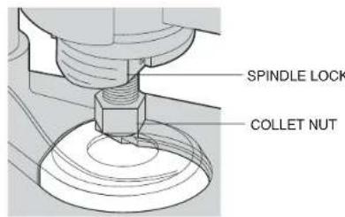
FIG.1
collet nut will turn approximately 3/4 of a turn and then become tight again. At this point the bit can't be removed. Using the same procedure, loosen the nut a second time. This lifts the collet and makes it easy to remove the bit.
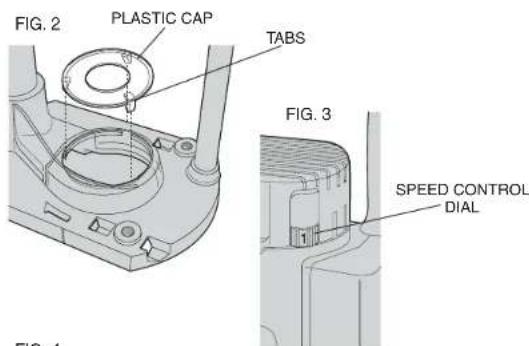
NOTE: Your router is equipped with a clear plastic cap over the cutting area. This cap assists with dust extraction. When installing a router bit over 1 - 1 / 8^* in diameter, ensure the plastic cap is removed or positioned above the cutting portion of the bit (Fig. 2). To remove the cap, push it from the bottom of the router. To re-install the cap, align the tabs (Fig. 2) and snap it into place.
Collets
NEVER TIGHTEN THE COLLET ON THIS TOOL WITHOUT FIRST INSTALLING A ROUTER BIT IN IT. TIGHTENING AN EMPTY COLLET CAN DAMAGE THE COLLET.
To change collet sizes, unscrew the collet assembly, as described above. The collet and the collet nut are connected. Do not attempt to remove the collet from the collet nut.
Controls
ELECTRONIC SPEED CONTROL DIAL
The speed of your router is variable. Use the electronic speed control (Fig. 3) dial to produce uniform cutting results in wood, plastics and aluminum. Use the lower settings (1-3) for large diameter cutters and the higher settings for small diameter cutters. See Table A for more information.
Adjusting the Depth of Cut
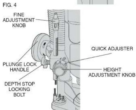
QUICK ADJUSTMENT USING RACK AND PINION HEIGHT ADJUSTMENT (FIG. 4)
1) UNPLUG THE ROUTER. It may be necessary to remove the plastic cap before making adjustments.
English
2) Unlock the plunge lock handle.
3) Lower the router carriage until the cutter is in contact with the workpiece
4) Tighten the plunge lock handle by turning it clockwise.
5) Turn the height adjustment knob counterclockwise until it hits the revolver depth stop (Fig. 5).
6) Set the quick adjuster to zero, by turning the inner ring knob clockwise.
7) Adjust the depth of cut by rotating the height adjust knob clockwise to the desired depth of cut. The adjustment range is indicated by the arrow.
8) Tighten the plunge limiter by turning the depth stop bolt clockwise. TRIPLE DEPTH ADJUSTMENT USING THE REVOLVER DEPTH STOP (FIG. 5)
The revolver depth stop can be used to set three different depths. This is useful for deep cuts, performed in steps.
1) Place a depth template between the depth stop and the revolver depth stop to adjust the exact cutting depth.
2) If required, set all three screws.
FINE ADJUSTMENT (FIG. 6)
Use the fine adjuster when not using a depth template, or if the depth of cut needs readjustment.
1) Adjust the depth of cut as described above.
2) Set the fine adjuster to zero using the inner ring. Hold the top portion while setting the lower ring to zero.
3) Rotate the fine adjuster to the required position. Graduations are on the top of the fine adjustment knob.
Lock-On/Lock-Off Switch (Fig. 7)
The lock-on/lock-off switch is located in the handle on the right side. The router is normally locked-off.
To start the router, press the thumb lock and squeeze the trigger. To lock the switch on, squeeze the trigger, press the thumb lock forward and release the trigger. To turn the router off, release the switch. If the tool is locked-on, press the trigger again and release the switch.
NOTE: Loosen the plunge limiter and allow the router carriage to return to its rest position before switching off.
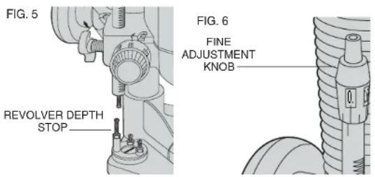
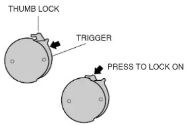
FIG. 7
Operation
After setting the cutting depth as described, locate the router such that the bit is directly over the place you will be cutting. With the router running, lower the unit smoothly down into the workpiece. (DO NOT JAM THE ROUTER DOWN). When the tool reaches the pre-set depth, tighten the plunge lock. When you have finished routing, loosen the plunge lock and let the spring lift the router directly out of the workpiece.
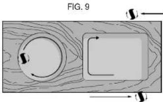
NOTE: Always feed the router opposite to the direction in which the cutter is rotating.
Direction Of Feed
Figs. 8 and 9 show proper direction of feed for some typical cuts.
Mold the outside edge of a piece of stock by a) mold the end grain, left to right, b) do the straight grain side moving left to right, c) finish the other end grain side, and d) do the remaining straight grain edge. The direction of feed is important in router usage. Be sure the cutter is rotating into the stock by moving left to right on outside edges and clockwise on inside cuts.
Dust Collection and Extraction
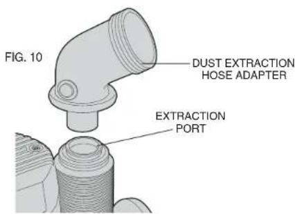
TO SET THE ROUTER FOR DUST EXTRACTION:
- Unplug router from power supply.
- If required, insert the dust extraction hose adapter into the dust extraction port (Fig. 10).
- Slip the end of any standard vacuum cleaner tube into the hose adapter.
- When using dust extraction, be sure that the vacuum cleaner is out of the way and secure so that it will not tip over or interfere with the router or workpiece. The vacuum hose and power cord must also be positioned so that they don't interfere with the router or
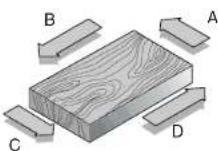
FIG.8
workpiece. If the vacuum cleaner or vacuum hose cannot be positioned properly, it should be removed.
-
Turn on vacuum cleaner before router.
-
Empty the vacuum cleaner as necessary.
NOTE: The router comes with a clear plastic removable guard over the cutting area. Do not attempt to plunge cut through the plastic guard. The guard is used to assist the dust collection.
Your router includes a dust extraction cap. Be sure it is in place over the dust extraction port if you are not using a vacuum.
Maintenance
CLEANING & LUBRICATION
Use only mild soap and damp cloth to clean the tool. Never let any liquid get inside the tool; never immerse any part of the tool into a liquid.
NOTE: Use only a DRY cloth to wipe the plunge rods. These rods require no lubrication. Lubricants attract dust, reducing the performance of your tool.
Accessories
Use only accessories that are recommended by the manufacturer for your model. Accessories that may be suitable for one tool, may become hazardous when used on another tool. Recommended accessories for use with your tool are available at extra cost from your local dealer or authorized service center. If you need assistance in locating any accessory for your tool, contact:
DeWALT Industrial Tool Company
626 Hanover Pike, P.O. Box 158
Hampstead, MD. 21074-0158
1-800-4-DEWALT (1-800-433-9258)
CAUTION: The use of any other accessory not recommended for use with this tool could be hazardous.
Important
To assure product SAFETY and RELIABILITY, repairs, maintenance and adjustment should be performed by authorized service centers or other qualified service organizations, always using identical replacement parts
Full Warranty
DeWALT heavy duty industrial tools are warranted for one year from date of purchase. We will repair, without charge, any defects due to faulty materials or workmanship. Arrangements have been made with the Industrial Tool Division of Black & Decker to provide warranty repairs for DeWALT tools. Please return the complete unit, transportation prepaid, to any Black & Decker Industrial Service Center or Authorized Service Station listed under "Tools, Electric" in the yellow pages. This warranty does not apply to accessories or damage caused where repairs have been made or attempted by others. This warranty gives you specific legal rights and you may have other rights which vary in certain states or provinces.
In addition to the warranty, DeWalt tools are covered by our:
30 DAY NO RISK SATISFACTION GUARANTEE
If you are not completely satisfied with the performance of your D-WALT heavy duty industrial tool, simply return it to the participating seller within 30 days for a full refund. Please return the complete unit, transportation prepaid. Proof of purchase may be required.

See 'Tools-Electric'
Yellow Pages
for Service & Sales
Table A
Your router is equipped with constant speed cutting—as you load the router, the selected cutting speed does not slow down during normal use. The electronic control governs the motor and gives you a consistent finish to your work. Only under very heavy loading will the speed of the unit fall below the governed speed.
To set the router speed (from 8,000 rpm to 24,000 rpm) rotate the speed control wheel shown in Fig. 3. The higher the number the higher the speed. Consult the table below to help select the proper speed for your application.
SPEED SELECTION CHART
| Material Cutter Dlam. Electronic Control Settings | ||||||
| Model # DW621 8,000 rpm 12,000 rpm 14,000 rpm 18,000 rpm 21,000 rpm 24,000 rpm | ||||||
| Hardwood, e.g., oak | Setting 1 Setting 2 Setting 3 Setting 4 Setting 5 Setting 6 | |||||
| Small (1/2") | - | - | O | X | XX X | |
| Medium (1/2"-1 1/8") | - | - | O | XX | X | |
| Large (over-1 1/8") | X | XX | O | - | - | |
| Softwood, e.g., pine | Small (1/2") | - | - | O | X | XX XX |
| Medium (1/2"-1 1/8") | - | O | X | XX | XX | |
| Large (over-1 1/8") | X | XX | O | - | - | |
| Plastic-laminated chipboard | Small (1/2") | - | - | O | X | XX XX |
| Medium (1/2"-1 1/8") | - | O | X | XX | XX | |
| Large (over-1 1/8") | O | XX | X | - | - | |
| Plastics/ Solid Surface | Small (1/2") | - | O | X | X | XX XX |
| Medium (1/2"-1 1/8") | - | O | XX | XX | X X | |
| Large (over-1 1/8") | X | XX | O | - | - | |
| This table can serve only as a guide, since wood was a living material. Within the same species of timber hardness and density vary. Speed settings are approximate. | ||||||
| KEY: XX very good X good O Satisfactory - not recommended | ||||||
POUR TOUT RENSEIGNEMENT SUPPLEMENTaire SUR CET OUTIL OU TOUT AUTRE OUTIL DEWALT, COMPOSER SANS FRAIS LE NUMERO :
18004-DEWALT(1800433-9258)
Français

RÉGLES DE SECURITE GÉNÉRALES
DeWALT Industrial Tool Company
626 Hanover Pike, P.O. Box 1
Hampstead, MD. 21074-0158
E-U.
Black & Decker Canada Inc.
100 Central Ave.
AJUSTE FINO (FIG. 6)
DeWalt Industrial Tool Company
626 Hanover Pike, P.O. Box 158
Hampstead, MD 21074-0158