DW625 - Router DEWALT - Free user manual and instructions
Find the device manual for free DW625 DEWALT in PDF.

| Brand | DeWalt |
| Model | DW625 |
| Product type | Electronic plunge router |
| Supply voltage | 120 V ~ |
| Max power | 750 W |
| No-load speed | 8,000 - 20,000 RPM (adjustable to 5 positions) |
| Plunge depth | 0 to 70 mm |
| Collet capacity | 6.4 mm (1/4 in) and 13 mm (1/2 in) |
| Max bit diameter | 60 mm (2-3/8 in) |
| Insulation | Double insulation |
| Plug type | Polarized (2-prong) |
| Electronic functions | Soft start, constant speed, speed regulator |
| Locking system | Spindle lock, plunge lock lever |
| Depth stop | 3-position turret stop with vernier scale |
| Included accessories | Two collets (6.4 and 13 mm), wrench, router guide adapter, dust extraction adapter |
| Approximate weight | 5.5 kg |
| Approximate dimensions (L x W x H) | 300 x 200 x 260 mm |
| Maintenance | Clean with dry air, damp cloth (mild soap) – do not immerse |
| Warranty | 3 years (limited) + 1 year free service contract |
| Intended use | Professional routing (wood, plastic) – not in wet environments |
Frequently Asked Questions - DW625 DEWALT
User questions about DW625 DEWALT
0 question about this device. Answer the ones you know or ask your own.
Ask a new question about this device
Download the instructions for your Router in PDF format for free! Find your manual DW625 - DEWALT and take your electronic device back in hand. On this page are published all the documents necessary for the use of your device. DW625 by DEWALT.
USER MANUAL DW625 DEWALT
Definitions: Safety Guidelines
The definitions below describe the level of severity for each signal word. Please read the manual and pay attention to these symbols.
DANGER: Indicates an imminently hazardous situation which, if not avoided, will result in death or serious injury.
WARNING: Indicates a potentially hazardous situation which, if not avoided, could result in death or serious injury.
CAUTION: Indicates a potentially hazardous situation which, if not avoided, may result in minor or moderate injury.
NOTICE: Indicates a practice not related to personal injury which, if not avoided, may result in property damage.
IF YOU HAVE ANY QUESTIONS OR COMMENTS ABOUT THIS OR ANY DEWALT TOOL, CALL US TOLL FREE AT: 1-800-4-DEWALT (1-800-433-9258).

WARNING: To reduce the risk of injury, read the instruction manual.
General Power Tool SafetyWarnings

WARNING! Read all safety warnings and all instructions. Failure to follow the warnings and instructions may result in electric shock, fire and/or serious injury.
SAVE ALL WARNINGS AND INSTRUCTIONS FOR FUTURE REFERENCE
The term "power tool" in the warnings refers to your mains-operated (corded) power tool or battery-operated (cordless) power tool.
1) WORK AREA SAFETY
a) Keep work area clean and well lit. Cluttered or dark areas invite accidents.
b) Do not operate power tools in explosive atmospheres, such as in the presence of flammable liquids, gases or dust. Power tools create sparks which may ignite the dust or fumes.
c) Keep children and bystanders away while operating a power tool. Distractions can cause you to lose control.
2) ELECTRICAL SAFETY
a) Power tool plugs must match the outlet. Never modify the plug in any way. Do not use any adapter plugs with earthed (grounded) power tools. Unmodified plugs and matching outlets will reduce risk of electric shock.
b) Avoid body contact with earthed or grounded surfaces such as pipes, radiators, ranges and refrigerators. There is an increased risk of electric shock if your body is earthed or grounded.
c) Do not expose power tools to rain or wet conditions. Water entering a power tool will increase the risk of electric shock.
d) Do not abuse the cord. Never use the cord for carrying, pulling or unplugging the power tool. Keep cord away from heat, oil, sharp edges or moving parts. Damaged or entangled cords increase the risk of electric shock.
e) When operating a power tool outdoors, use an extension cord suitable for outdoor use. Use of a cord suitable for outdoor use reduces the risk of electric shock.
If operating a power tool in a damp location is unavoidable, use a ground fault circuit interrupter (GFCI) protected supply. Use of a GFCI reduces the risk of electric shock.
3) PERSONAL SAFETY
a) Stay alert, watch what you are doing and use common sense when operating a power tool. Do not use a
power tool while you are tired or under the influence of drugs, alcohol or medication. A moment of inattention while operating power tools may result in serious personal injury.
b) Use personal protective equipment. Always wear eye protection. Protective equipment such as dust mask, nonskid safety shoes, hard hat, or hearing protection used for appropriate conditions will reduce personal injuries.
c) Prevent unintentional starting. Ensure the switch is in the off position before connecting to power source and/or battery pack, picking up or carrying the tool. Carrying power tools with your finger on the switch or energizing power tools that have the switch on invites accidents.
d) Remove any adjusting key or wrench before turning the power tool on. A wrench or a key left attached to a rotating part of the power tool may result in personal injury.
e) Do not overreach. Keep proper footing and balance at all times. This enables better control of the power tool in unexpected situations.
f) Dress properly. Do not wear loose clothing or jewelry. Keep your hair, clothing and gloves away from moving parts. Loose clothes, jewelry or long hair can be caught in moving parts.
g) If devices are provided for the connection of dust extraction and collection facilities, ensure these are connected and properly used. Use of dust collection can reduce dust-related hazards.
4) POWER TOOL USE AND CARE
a) Do not force the power tool. Use the correct power tool for your application. The correct power tool will do the job better and safer at the rate for which it was designed.
b) Do not use the power tool if the switch does not turn it on and off. Any power tool that cannot be controlled with the switch is dangerous and must be repaired.
c) Disconnect the plug from the power source and/or the battery pack from the power tool before making any adjustments, changing accessories, or storing power tools. Such preventive safety measures reduce the risk of starting the power tool accidentally.
d) Store idle power tools out of the reach of children and do not allow persons unfamiliar with the power tool or these instructions to operate the power tool. Power tools are dangerous in the hands of untrained users.
e) Maintain power tools. Check for misalignment or binding of moving parts, breakage of parts and any other condition that may affect the power tool's operation. If damaged, have the power tool repaired before use. Many accidents are caused by poorly maintained power tools.
f) Keep cutting tools sharp and clean. Properly maintained cutting tools with sharp cutting edges are less likely to bind and are easier to control.
g) Use the power tool, accessories and tool bits, etc. in accordance with these instructions, taking into account the working conditions and the work to be performed. Use of the power tool for operations different from those intended could result in a hazardous situation.
5) SERVICE
a) Have your power tool serviced by a qualified repair person using only identical replacement parts. This will ensure that the safety of the power tool is maintained.
SAVE THESE INSTRUCTIONS FOR FUTURE USE
Double Insulation
Double insulated tools are constructed throughout with two separate "layers" of electrical insulation between you and the tool's electrical system.
Tools built with this insulation system are not intended to be grounded. As a result, your tool is equipped with a two-prong plug which permits you to use extension cords without concern for maintaining a ground connection.
NOTE: Double insulation does not take the place of normal safety precautions when operating this tool. The insulation system is for added protection against injury resulting from a possible electrical insulation failure within the tool.
CAUTION: When servicing all tools, USE ONLY IDENTICAL REPLACEMENT PARTS.
Polarized Plugs
Polarized plugs (one blade is wider than the other) are used on equipment to reduce the risk of electric shock. When provided, this plug will fit into a polarized outlet only one way. If the plug does not fit fully into the outlet, reverse the plug. If it still does not fit, contact a qualified electrician to install the proper outlet. Do not change the plug in any way. Repair or replace damaged cords.
Additional Specific Instructions for Routers
- Hold power tools by insulated gripping surfaces, because the cutter may contact its own cord. Cutting a "live" wire may make exposed metal parts of the tool "live" and shock the operator.
- Use clamps or another practical way to secure and support the workpiece to a stable platform. Holding the work by your hand or against the body leaves it unstable and may lead to loss of control.
- Metal cutting with router: If using router for metal cutting, clean out tool often. Metal dust and chips often accumulate on interior surfaces and could create a risk of serious injury, electrical shock or death.
-
Never run the motor unit separate from the base. The motor is not designed to be handheld.
-
Keep handles dry, clean and free from oil and grease. This will enable better control of the tool.
- Maintain a firm grip with both hands on the tool to resist starting torque. Maintain a firm grip on the tool at all times while operating.
- Use sharp cutters. Dull cutters may cause the router to swerve or stall under pressure.
- Keep hands away from cutting area above and below the base. Never reach under the workpiece for any reason.
- Keep the router base firmly in contact with the workpiece when cutting.
- Never touch the bit immediately after use. It may be extremely hot.
- Do not use router bits with a diameter in excess of 2 - 3 / 8'' (60 mm) in this tool.
- Always follow the bit manufacturer's speed recommendations as some bit designs require specific speeds for safety or performance. If you are unsure of the proper speed or are experiencing any type of problem, contact the bit manufacturer.
- Do not hand-hold the router in an upside-down or horizontal position. The motor can separate from the base if not properly attached according to the instructions.
- Before starting the motor, check to see that the cord will not snag or impede the routing operation.
- Before starting the motor, clear the work area of all foreign objects.
- Keep cutting pressure constant. Do not overload motor.
- Provide clearance under workpiece for bit when through-cutting.
-
Do not press spindle lock button while the motor is running. Doing so can damage the spindle lock.
Always make sure the work surface is free from nails and other foreign objects. Cutting into a nail can cause the bit and the tool to jump. -
Be sure that the motor has stopped completely before you lay the router down. If the cutter head is still spinning when the tool is layed down, it could cause injury or damage.
- Be sure that the router bit is clear of the workpiece before starting motor. If the bit is in contact with the workpiece when the motor starts it could make the router jump, causing damage or injury.
Air vents often cover moving parts and should be avoided. Loose clothes, jewelry or long hair can be caught in moving parts. - An extension cord must have adequate wire size (AWG or American Wire Gauge) for safety. The smaller the gauge number of the wire, the greater the capacity of the cable, that is 16 gauge has more capacity than 18 gauge. An undersized cord will cause a drop in line voltage resulting in loss of power and overheating. When using more than one extension to make up the total length, be sure each individual extension contains at least the minimum wire size. The following table shows the correct size to use depending on cord length and nameplate ampere rating. If in doubt, use the next heavier gauge. The smaller the gauge number, the heavier the cord.
| Minimum Gauge for Cord Sets | ||||||
| Ampere Rating | Volts | Total Length of Cord in Feet (meters) | ||||
| 120 V | 25 (7.6) | 50 (15.2) | 100 (30.5) | 150 (45.7) | ||
| 240 V | 50 (15.2) | 100 (30.5) | 200 (61.0) | 300 (91.4) | ||
| More Than | Not More Than | AWG | ||||
| 0 6 | 18 16 16 | 4 | ||||
| 6 10 | 18 16 14 | 12 | ||||
| 10 12 | 16 16 14 | 12 | ||||
| 12 16 | 14 12 Not Recommended | |||||
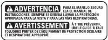
WARNING: ALWAYS use safety glasses. Everyday eyeglasses are NOT safety glasses. Also use face or dust mask if cutting operation is dusty. ALWAYS WEAR CERTIFIED SAFETY EQUIPMENT:
ANSI Z87.1 eye protection (CAN/CSA Z94.3)
ANSI S12.6 (S3.19) hearing protection,
- NIOSH/OSHA/MSHA respiratory protection.
WARNING: Some dust created by power sanding, sawing, grinding, drilling, and other construction activities contains chemicals known to the State of California to cause cancer, birth defects or other reproductive harm. Some examples of these chemicals are:
- lead from lead-based paints,
crystalline silica from bricks and cement and other masonry products, and
arsenic and chromium from chemically-treated lumber.
Your risk from these exposures varies, depending on how often you do this type of work. To reduce your exposure to these chemicals: work in a well ventilated area, and work with approved safety equipment, such as those dust masks that are specially designed to filter out microscopic particles.
- Avoid prolonged contact with dust from power sanding, sawing, grinding, drilling, and other construction activities. Wear protective clothing and wash exposed areas with soap and water. Allowing dust to get into your mouth, eyes, or lay on the skin may promote absorption of harmful chemicals.
WARNING: Use of this tool can generate and/or disperse dust, which may cause serious and permanent respiratory or other injury. Always use NIOSH/OSHA approved respiratory protection appropriate for the dust exposure. Direct particles away from face and body.
WARNING: Always wear proper personal hearing protection that conforms to ANSI S12.6 (S3.19) during use. Under some conditions and duration of use, noise from this product may contribute to hearing loss.
The label on your tool may include the following symbols. The symbols and their definitions are as follows:
The label on your tool may include the following symbols. The symbols and their definitions are as follows:
V..... volts A. .amperes
Hz..... hertz W. .watts
min.....minutes \~or AC....alternating
or DC...direct current current
Class I Construction or AC/DC...alternating
(grounded) or direct
Class I Construction current
double insulated) no load
../min. per minute speed
BPM...beats per minute n..rated
IPM............impacts per minute speed
RPM.......revolutions per
minute terminal
sfpm.....surface feet A.. safety alert
per minute symbol
SPM.........strokes per minute ..visible
radiation
SAVE THESE INSTRUCTIONS FOR FUTURE USE
Motor
Be sure your power supply agrees with the nameplate marking. Voltage decrease of more than 10% will cause loss of power and overheating. DEWALT tools are factory tested; if this tool does not operate, check power supply.
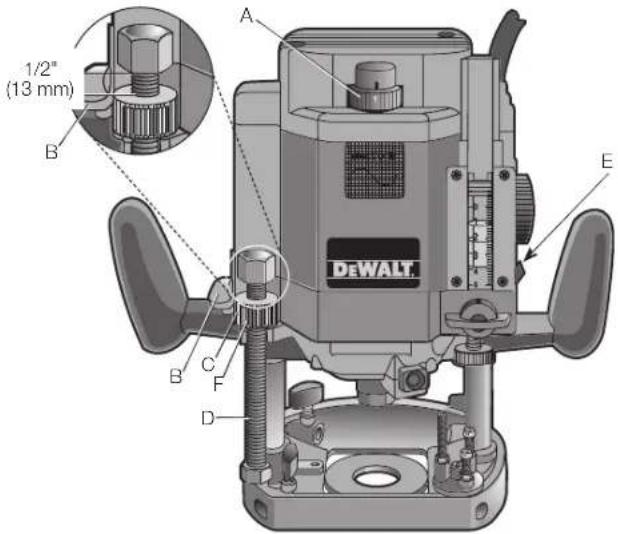
FIG.1
COMPONENTS (Fig. 1)
WARNING: Never modify the power tool or any part of it. Damage or personal injury could result.
A. Speed control wheel
D. Height stop rod
B. Switch
E. Plunge lock lever
C. Thumb wheel
F. Quick release button
INTENDED USE
This heavy-duty router is designed for professional routing applications.
DO NOT use under wet conditions or in presence of flammable liquids or gases.
This is a professional power tool. DO NOT let children come into contact with the tool. Supervision is required when inexperienced operators use this tool.
The electronic motor control system has two basic features.
A. Soft start - When you turn on the router, you will notice that it does not have the jerk from the rapid acceleration of the motor. This router has a starting circuit which accelerates the motor up to speed smoothly, without jerking, and allows you to maintain easier control of the router during the start up period.
B. Constant speed cutting - As you load the router, the selected cutting speed does not slow down during normal use. The electronic control governs the motor and gives you a consistent finish to your work. Only under very heavy loading will the speed of the unit fall below the governed speed.
To set the router speed (from 8,000 rpm to 20,000 rpm) rotate the speed control wheel (A) shown in Figure 1. The higher the number the higher the speed. Consult TABLE 1 below to help select the proper speed for your application.
TABLE 1: SPEED SELECTION CHART
| DIAL SETTING APPROX. RPM | |
| 1 8,000 | |
| 2 12,000 | |
| 3 16,000 | |
| 4 18,000 | |
| 5 20,000 | |
The speeds in this chart are approximate and are for reference only. Your router may not exactly produce the speed listed for the dial setting.
WARNING: Always follow the bit manufacturer's speed recommendations as some bit designs require specific speeds for
safety or performance. If you are unsure of the proper speed or are experiencing any type of problem, contact the bit manufacturer.
WARNING: Do not operate tools rated "AC only" on a DC supply. Loss of speed control may result, causing tool damage and possible hazard to the operator.
WARNING: If the speed control ceases to operate, or is intermittent, stop using the tool immediately. Take it to a DFWALT factory or authorized service facility for repair.
NOTICE: The router is equipped with electronics to monitor and maintain the speed of the tool while cutting. In low and medium speed operation, the speed control prevents the motor speed from decreasing. If you expect to hear a speed change and continue to load the motor, you could damage the motor by overheating. Reduce the depth of cut and/or slow the feed rate to prevent tool damage.
PREPARATION FOR USE
The motor in this router is high-powered (750 Watts, max.). Despite this, it is advisable to cut deep grooves or remove large amounts of material in two or more passes.
Switch (Fig. 1)
TO SWITCH ON THE MACHINE
WARNING: Always pull the plug on the cord set out of its receptacle when changing a cutter or fitting the accessories in order to avoid any chance of an accident.
Push the switch (B) up for ON or down for OFF.
OPERATION (Fig. 1, 2)
WARNING: To reduce the risk of injury, turn unit off and disconnect it from power source before installing and removing accessories, before adjusting or when making repairs. An accidental start-up can cause injury.
CAUTION: Before connecting tool to power source, check to see that the switch is in the "OFF" position. An accidental start-up can cause injury.
NOTE: Before installing a router bit in your unit, position the tool so that the collet is easily accessible. To do this, rotate the height stop thumb wheel (C), shown, counterclockwise until it is about 1/2'' (13 mm) from the top of the threaded height stop rod (D). Raise the plunge lock lever (E), shown in Figure 2, and let the router rise to its full height lock the tool in place.
TECHNICAL DATA
| Model DW625 | |
| Voltage | 120 |
| Speed 8,000 - 20,000 rpm | |
| Insulation double insulated | |
| Column spring loaded twin column | |
| Plunging stroke 2-3/4" (70 mm) | |
| Routing depth 0-70 mm adjustable | |
| Cutter mounting precision collet, size | |
| 1/4" (6.4 mm) and 1/2" (13 mm) | |
| Cutter cap max. 2-3/8" (60 mm) | |
| Routing | (shallow) |
| Rotary depth stop 3 stage depth position | |
Controls
NOTE: Before operating any of the controls, read this whole section.
PLUNGE LOCK LEVER (FIG. 2)
The plunge lock lever (E) allows the router bit to be plunged directly into the workpiece. Simply raise the plunge lock lever when you
want to lower the router into the work, as shown. You can lower the unit until it reaches your preset stop. To lock the tool in place anywhere along its vertical travel, depress the lever.
BIT INSTALLATION AND REMOVAL (FIG. 3, 4)
IMPORTANT NOTE: Always snap the collet (I) firmly into the collet nut (G), (past the retainer spring) before installing a bit.
Use the supplied wrench and the spindle lock button (H) as necessary to loosen (counterclockwise) the collet nut, as shown. Insert the round shank of the desired router bit into the loosened collet as far as it will go and then pull it out about 1/16'' (1.6 mm)
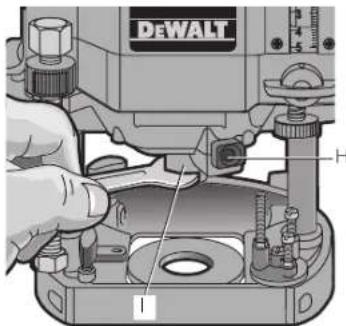
Hold the spindle shaft by depressing the spindle lock button while firmly tightening the collet nut with the wrench.
Your router has a unique locking system for retaining the bit. When removing a bit, the collet nut must be loosened with the wrench. The collet nut will turn approximately 3/4 of a turn and then become tight again. At this point the bit can't be removed. Using the same procedure, loosen the nut a second time. This lifts the collet and makes it very easy to remove the bit.
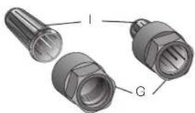
FIG.4
COLLETS (FIG. 3, 4)
WARNING:Projectile hazard. Only use bits with shanks that match the installed collet. Smaller shank bits will not be secure and could become loose during operation.
CAUTION: Never tighten the collet without first installing a router bit in it. Tightening an empty collet, even by hand, can damage the collet.
Two collets are included with the motor: one 1/4'' (6.4 mm) and one 1/2'' (13 mm).
To change collets, unscrew the collet assembly, as described above, sharply pull the old collet out of the collet nut and insert the new collet. Push firmly so that it snaps past the retainer spring in the collet nut.
HEIGHT STOP ROD AND HEIGHT STOP THUMB WHEEL (FIG. 1)
The height stop rod (D) and thumb wheel (C) limit how high the unit can travel up the rails. The system is adjustable from full down where the unit cannot rise regardless of the position of the plunge release lever to full up where the bottom of the collet is 2-7/8" (73 mm) above the workpiece.
For convenience, the thumb wheel is equipped with a quick release button (F) that allows you to disengage the threads for fast positioning by simply depressing the button in the side of the wheel.
NOTE: It is easier to move the height stop thumb wheel UP if the plunge release lever is locked and easier to move the thumb wheel DOWN if the unit is first moved down by releasing the plunge release lever and then tightening it.
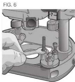
MULTI-POSITION TURRET STOP (FIG. 5-7)
WARNING: Do not change the turret stop while the router is running. This will place your hands too near the cutter head.
The turret stop (J) limits the downward distance that the tool can be plunged. It consists of three screws of different lengths that serve to define the depth of cut by limiting the travel of the depth stop bar (K). Routing depth can be set by selecting the screw of the appropriate length on the turret. The turret is rotatable with detent stops to properly align the screws.
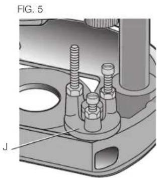
It is the interaction of the depth stop bar and the turret stop that determine the routing depth.
If none of the provided screws seems close to the desired height each can be adjusted by loosening the hex nut at the bottom and then turning the screw either in or out to make it the proper length. After adjusting this screw be sure to tighten the hex nut at the bottom (Fig. 6.)
Refer to section Setting the Routing Depth for instructions on how to use the turret stop in an actual operation.
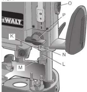
DEPTH STOP BAR AND VERNIER (FIG.7) The depth stop bar K FIG.7
The depth stop bar (K) contacts the selected screw in the turret stop to limit the routing depth. At the bottom of the depth stop bar is a threaded shaft, a spring (L) and a knurled knob (M), as shown.
A precision vernier scale (N) is provided for extremely accurate adjustment of the routing depth.
Refer to Setting the Routing Depth for instructions on how to use the depth stop bar and vernier in an actual o
Familiarization
Please take a little time now and, without plugging the tool in, practice with these adjustments and controls and become familiar with their operation. Only with a complete, "hands on" understanding of these systems will you be able to get the most out of this quality router.
Setting the Routing Depth (Fig. 7)
To set the routing depth follow the steps below:
- Install the desired router bit as described previously.
-
Position the height stop thumb wheel at the top of the height stop rod. You can either turn the thumb wheel or use the handy quick release button. Refer to Height Stop Rod and Height Stop Thumb Wheel.
-
Adjust the depth stop bar to the top of its travel by rotating the depth stop control knob (O).
- Rotate the turret stop to position the shortest screw under the depth stop bar.
- Raise the plunge release lever and push the router down until the end of the bit just touches the workpiece.
- Lower the depth stop bar until the knurled knob on the bottom of it touches the selected screw in the turret stop.
- Raise or lower the plastic vernier to align the hairline in the vermier with the 0 mark on the graduated scale, as shown.
- Using the depth stop control knob, raise the depth stop bar and align the desired mark on the graduated scale with the hairline in the vernier, as shown (the scale is graduated in 1/16ths of an inch).
- Tighten the depth stop bar clamp (P).
- The router is now set to cut to the set depth when plunged into the workpiece.
Fine Adjustment of Routing Depth (Fig. 7)
If, after setting the desired depth of cut, a small adjustment is needed, it is not necessary to go through the entire procedure for setting the depth. Minor adjustment can be easily made by rotating the knurled knob (M) on the bottom end of the depth stop bar (K), as shown in Figure 7.
Rotating the knob clockwise (looking down from the top of the router) will result in a more shallow cut. Rotating the knob counterclockwise will result in a deeper cut. One complete rotation of the knob represents about 1 mm in depth adjustment.
Using the Turret Stop for Sequential Routing Depth Settings (Fig. 8)
It is recommended that particularly deep grooves be cut with several passes rather than one deep pass. In order to do this and still maintain accuracy of depth when the job is finished, perform the following procedure.
- Set the final desired routing depth. Refer to Setting the Routing Depth. For the purpose of this discussion, assume that the desired depth is 1/2 (13 mm).
- With a depth of 1 / 2 (13 mm). set on the shortest screw (Q) in the turret stop (J), adjust the second shortest screw (R) to a point about halfway between the bottom of the knurled knob and the top of the shortest screw, as shown.
- Leave the vernier setting alone and turn the adjusted second shortest screw into position under the depth stop bar.
- Make your first cut at this setting.
- Rotate the turret stop so that the shortest screw is directly under the depth stop bar and make your final cut.
NOTE: The third screw in the turret stop is provided if your cut is even deeper and you want to make three cuts to achieve the final depth, or set final depth for multiple cuts at one time.
Operation
CAUTION: Turn the router on before plunging the cutter head into the workpiece.
After setting the cutting depth as described, locate the router such that the bit is directly over the place you will be cutting. With the router running, lower the unit smoothly down into the workpiece. DO NOT JAM THE ROUTER DOWN. When the tool reaches the pre-set depth, depress the plunge lock lever (E, Fig. 1). When you have finished routing, raise the lever and let the spring lift the router directly out of the workpiece.
All common routing tasks can be performed with ease with the plunge cut router: grooving, rabbeting, recessing, veining, and profiling on all types of wood and plastic.
Always feed the router opposite to the direction in which the cutter is rotating.
Only carbide-tipped cutters should be used on panels faced with plastic laminates. The hard laminates will quickly dull steel cutters.
Direction Of Feed (Fig. 9, 10)
The direction of feed is very important when routing and can make the difference between a successful job and a ruined project. Figures 9 and 10 show proper direction of feed for some typical cuts.
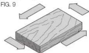
Mold the outside edge of a piece
of stock by molding the end grain, left to right, molding the straight grain side moving left to right, finish the other end grain side, and molding the remaining straight grain edge.
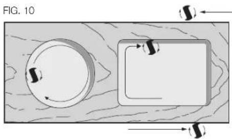
The direction of feed is important in router usage. Be sure the cutter is rotating into the stock by moving left to right on outside edges and clockwise on inside cuts.
WARNING: Avoid climb-cutting (cutting in direction opposite than shown in Figure 10). Climb-cutting increases the chance for loss of control resulting in possible injury. When climb-cutting is required (backing around a corner), exercise extreme caution to maintain control of router. Make smaller cuts and remove minimal material with each pass.
Using the Edge Guide (Fig. 11, 12)
The DW6913 edge guide, available at extra cost, will increase the versatility of your router. Assemble the guide as shown in Figure 12. When it's fully assembled, insert the two bars through the holes in the router base as shown. Adjust as needed for parallel routing. The guide will adjust in, all the way to the cutter. In some cases the plastic slides on the guide will interfere with the cutter if they are not loosened and pushed back to provide clearance. Loosen the two screws on each slide and adjust it accordingly.
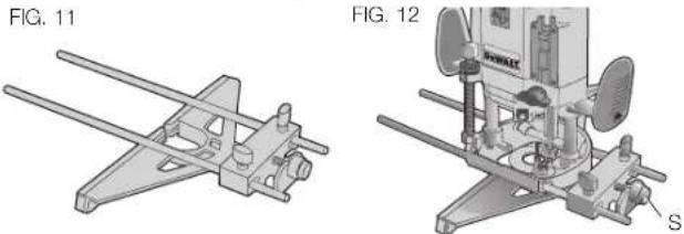
A fine adjust feature is included on the edge guide and is operated by rotating the fine adjust knob (S). Turn the knob clockwise to move the guide in (closer to the bit). Turn the knob counterclockwise to move the guide out (away from the bit).
Template Guide Adapter (Fig. 13)
Your router comes equipped with a template guide adapter (T) and two mounting screws. Put these away in a safe place for future use.
Connecting a Dust Extractor (Fig 14)
The dust extractor adapter consists of the body (U), the cover (V), and the hose guide (W). Assemble as follows:
- Slide the cover onto the main body and let it click into place.
- Connect a dust extractor hose to the outlet.
- Loosen the screw on the top cover of the router and secure the hose guide in place.
- When using dust extraction, be sure that the vacuum cleaner is out of the way and secure so that it will not tip over or interfere with the router or workpiece. The vacuum hose and power cord must also be positioned so that they don't interfere with the router or workpiece. If the vacuum cleaner or vacuum hose cannot be positioned properly, it should be removed.
MAINTENANCE
WARNING: To reduce the risk of injury, turn unit off and disconnect it from power source before installing and removing accessories, before adjusting or when making repairs. An accidental start-up can cause injury.
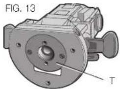
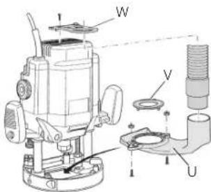
FIG. 14
Cleaning
WARNING: Blow dirt and dust out of all air vents with clean, dry air at least once a week. To minimize the risk of eye injury, always wear ANSI Z87.1 approved eye protection when performing this.
WARNING: Never use solvents or other harsh chemicals for cleaning the non-metallic parts of the tool. These chemicals may weaken the plastic materials used in these parts. Use a cloth dampened only with water and mild soap. Never let any liquid get inside the tool; never immerse any part of the tool into a liquid.
Accessories
WARNING: Since accessories, other than those offered by DEWALT, have not been tested with this product, use of such accessories with this tool could be hazardous. To reduce the risk of injury, only DEWALT recommended accessories should be used with this product.
Recommended accessories for use with your tool are available at extra cost from your local dealer or authorized service center. If you need assistance in locating any accessory, please contact DEWALT Industrial Tool Co., 701 East Joppa Road, Towson, MD 21286, call 1-800-4-DEWALT (1-800-433-9258) or visit our website: www. dewalt.com.
Repairs
To assure product SAFETY and RELIABILITY, repairs, maintenance and adjustment (including brush inspection and replacement) should be performed by a DEWALT factory service center, a DEWALT authorized service center or other qualified service personnel. Always use identical replacement parts.
Register Online
Thank you for your purchase. Register your product now for:
WARRANTY SERVICE: Registering your product will help you obtain more efficient warranty service in case there is a problem with your product.
CONFIRMATION OF OWNERSHIP: In case of an insurance loss, such as fire, flood or theft, your registration of ownership will serve as your proof of purchase.
FOR YOUR SAFETY: Registering your product will allow us to contact you in the unlikely event a safety notification is required under the Federal Consumer Safety Act.
Register online at www.dewalt.com/register.
Three Year Limited Warranty
DEWALT will repair, without charge, any defects due to faulty materials or workmanship for three years from the date of purchase. This warranty does not cover part failure due to normal wear or tool abuse. For further detail of warranty coverage and warranty repair information, visit www.dewalt.com or call 1-800-4-DEWALT (1-800-433-9258). This warranty does not apply to accessories or damage caused where repairs have been made or attempted by others. This warranty gives you specific legal rights and you may have other rights which vary in certain states or provinces.
In addition to the warranty, DEWALT tools are covered by our:
1 YEAR FREE SERVICE
DEWALT will maintain the tool and replace worn parts caused by normal use, for free, any time during the first year after purchase.
90 DAY MONEY BACK GUARANTEE
If you are not completely satisfied with the performance of your DeWALT Power Tool, Laser, or Nailer for any reason, you can return it within 90 days from the date of purchase with a receipt for a full refund - no questions asked.
LATIN AMERICA: This warranty does not apply to products sold in Latin America. For products sold in Latin America, see country specific warranty information contained in the packaging, call the local company or see website for warranty information.
FREE WARNING LABEL REPLACEMENT: If your warning labels become illegible or are missing, call 1-800-4-DEWALT (1-800-433-9258) for a free replacement.
Colonne Double aressort
Course plongeante 70 mm (2-3/4 po)
REEMPLACEMENT Gratisuit DES ETIQUETTES
Local D, Col. Obrera (55) 5588 9377
MERIDA, YUC
Calle 63 #459-A - Col. Centro (999) 928 5038
MONTERREY, N.L.
DEWALT Industrial Tool Co., 701 East Joppa Road, Towson, MD 21286
(MAY15) Part No. N428614 DW625 Copyright © 1999, 2002, 2004, 2007, 2014, 2015 DEWALT
The following are trademarks for one or more DEWALT power tools: the yellow and black color scheme; the "D" shaped air intake grill; the array of pyramids on the handgrip; the kit box configuration; and the array of lozenge-shaped humps on the surface of the tool.