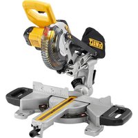
DW7440RS - Saw DEWALT - Free user manual and instructions
Find the device manual for free DW7440RS DEWALT in PDF.

User questions about DW7440RS DEWALT
0 question about this device. Answer the ones you know or ask your own.
Ask a new question about this device
Download the instructions for your Saw in PDF format for free! Find your manual DW7440RS - DEWALT and take your electronic device back in hand. On this page are published all the documents necessary for the use of your device. DW7440RS by DEWALT.
USER MANUAL DW7440RS DEWALT
Works with most jobsite table saws as designed. Some saws may require a plywood surface for attachment to stand (see Table Saw Bracket Mounting for specific instructions).
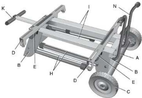
A. Axle
I. Beams
B. Leg supports J. Locator clip
C. Wheels K. Handle
D. Saw mounting bracket L. Handle lock
E. Bracket release levers M. Rubber bumpers
F. Leg release levers N. Kickstand
G. Locking pins O. Tube plugs
H. Legs
* Works with most jobsite table saws as designed. Some saws may require a plywood surface for attachment to stand (see Table Saw Bracket Mounting for specific instructions).
text_image
K D B E H D I N A B E C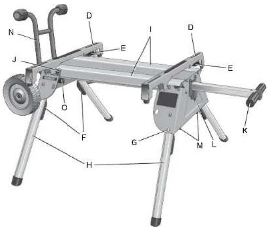
text_image
N J O F H G M L K E I D D EDefinitions: Safety Guidelines
The definitions below describe the level of severity for each signal word. Please read the manual and pay attention to these symbols.
▲DANGER: Indicates an imminently hazardous situation which, if not avoided, will result in death or serious injury.
WARNING: Indicates a potentially hazardous situation which, if not avoided, could result in death or serious injury.
ACAUTION: Indicates a potentially hazardous situation which, if not avoided, may result in minor or moderate injury.
NOTICE: indicates a practice not related to personal injury which, if not avoided, may result in property damage.
IF YOU HAVE ANY QUESTIONS OR COMMENTS ABOUT THIS OR ANY DEWALT TOOL, CALL US TOLL FREE AT: 1-800-4-DEWALT (1-800-433-9258)
DW7440RS Rolling Table Saw Stand with Folding Legs
▲WARNING: For your own safety, read the table saw instruction manual before using any accessory. Failure to heed these warnings may result in personal injury and serious damage to the table saw and the accessory. When servicing this tool, use only identical replacement parts.
This stand is designed for use with table saws only. The DW7440RS stand has been evaluated by UL for use with the DW744, DW744X and the DW745 table saws. This stand can be used with other table saw models but these models have not been evaluated for use with this stand by UL. If you experience a problem with your DEWALT purchase, please call 1-800-4-DEWALT (1-800-433-9258).
Tools Required
Phillips screwdriver
Socket or wrench set
Contents
Stand Carriage head bolts (2)
Mounting brackets (2) M8 lock nuts (4)
Wheels (2) Rear axle
Rubber bumpers (2) M4 screws (2)
Washers (4) M4 lock nuts (2)
Kickstand assembly M6 screws (4)
Tube plugs (2) M4 hex wrench
Saw mounting hardware: hex head bolts (4), washers (8), nuts (4), lock washers (4)
General Safety Instructions for Table Saw Accessories
⚠ WARNING: To reduce the risk of personal injury:
- ALWAYS use eye protection. All users and bystanders must wear eye protection that conforms to ANSI Z87.1.
- Ensure all stand fasteners are securely fastened and that all stand mechanisms are in proper working order before operating the table saw.
- DO NOT exceed the weight this stand can hold. The DW7440RS table saw stand is designed to support 150 lbs. (68 kgs.) safely in a work environment. It is unsafe to climb, sit or stand on the stand.
- Follow the mounting instructions carefully. Fasten the tool to the saw mounting brackets securely as instructed.
- DO NOT modify or use stand for operations for which it is unintended.
- DO NOT use the stand on uneven surfaces. DO NOT use the stand with the legs folded and stand sitting on the ground. The stand is designed to be used on a flat, stable surface.
ASSEMBLY
Attaching the Wheels and Axle
-
Attach the axle (A) to the leg support (B) by aligning the pre-drilled holes. Ensure the long end of the axle is to the rear of the stand as shown. Secure axle to leg support using two carriage bolts, washers and lock nuts provided.
-
Place the wheels (C) on the axle (A) and secure with washers and lock nuts as shown. Tighten wheel and axle nuts securely.
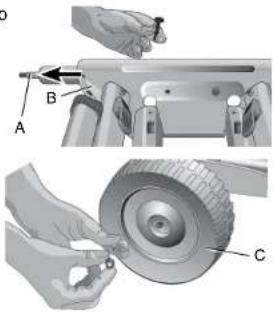
text_image
Technical diagram showing mechanical assembly with labeled parts A, B, and C, including a tool and tool interacting with a car wheel.Attaching the Kickstand
Insert the tube plugs (O) into the end of the kickstand tube (N). The groove in the tube plug should be facing down as shown. Be sure that the holes (P) in the tube plugs are in line with the holes (Q) in the kickstand tube before inserting the tube plugs.
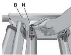
Insert the kickstand tube (N) through the holes in the leg support (B) on the wheel-axle side of the stand. Be sure the kickstand is pointing up when the stand is an upright position. Secure the kickstand to the beams (I) with the four M6 screws provided as shown (below, left).
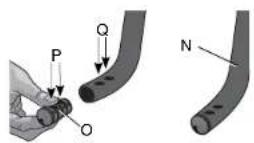
The hex wrench may be stored in the end of the tube plug as shown for future use.
text_image
B N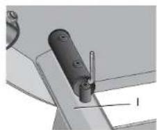
natural_image
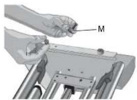
Mechanical component diagram showing a lever and pin assembly (no text or symbols)Attaching the Rubber Bumpers
Attach the two rubber bumpers (M) to the handle side leg support as shown using the M4 screws and lock nuts provided.
natural_image
Illustration of a hand holding a tool labeled 'M' over a mechanical component (no text or symbols present)Table Saw Bracket Mounting
WARNING: To reduce the risk of injury, turn unit off, disconnect machine from power source before assembling the table saw to the table saw stand. An accidental start-up can cause injury.
⚠ WARNING: For your own safety, read and understand the table saw instruction manual before using. Failure to heed these warnings may result in personal injury and serious damage to the table saw and the accessory.
WARNING: The saw mounting brackets provided with this stand are equipped with lever locks. To reduce the risk of injury, DO NOT modify the mounting bracket lever locks.
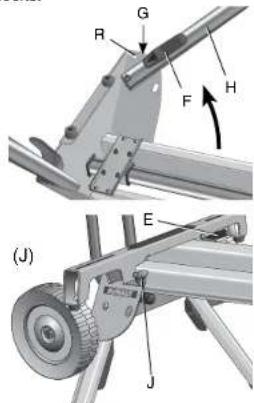
- Unfold the legs by depressing the leg release levers (F). Rotate the legs until the locking pin (G) clicks into its detent (R).
- Turn the stand upright. The stand should be stable and should not rock.
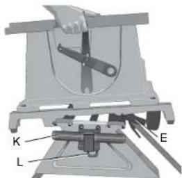
▲WARNING: Be sure that the locking pins have engaged and the legs are firmly held in place. - The locator clip keeps the saw from sliding left or right during cutting operations and during transport. Install the mounting brackets on to the beam as shown by engaging the concave front lip of the
text_image
Technical diagram showing mechanical assembly with labeled parts (R, G, F, H, E, J) and directional arrows indicating motion or force.mounting bracket with the rounded front edge of the beam. One of the brackets must engage the locator clip (J). The mounting bracket release levers (E) must be positioned to the rear of the stand as shown.
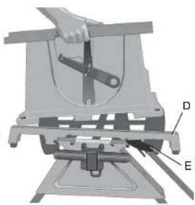
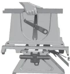
- Measure the distance between the mounting holes of the table saw. Position the second mounting bracket onto the beam at this distance from the first mounting bracket.
- Align the holes in the table saw base with the slots in the saw mounting brackets (D).
- Feed a hex head bolt with flat washer installed through each of the four holes in the table saw base and mounting brackets. Secure each location with a flat washer, lock washer and nut provided.
⚠ WARNING: To reduce the risk of personal injury, be sure the table saw is fully anchored on the stand.
WARNING: The table saw must be positioned on the tool mount so that all four corners can be bolted to the mounting brackets. If the saw is mounted properly, the mounting brackets will be positioned perpendicular to the stand rail when the saw is placed on the stand.
text_image
Technical diagram of a mechanical assembly with labeled parts D and E, showing a hand operating a tool.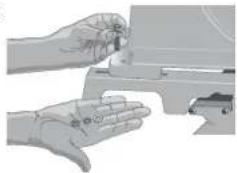
natural_image
Illustration of a hand holding a mechanical component, no text or symbols visibleIf your saw holes do not line up with the mounting bracket slots, please follow the alternative mounting instructions below. Please call DEWALT customer support at 1-800-4-DEWALT (433-9258) for technical issues.
You may need additional hardware to complete the following mounting directions. If your saw has mounting holes that do not line up with the slots in the mounting brackets, please complete the following steps:
Step 1: Cut a piece of 3/4" plywood 2" longer and 2" wider than the base of your saw. The plywood should not exceed 23-1/2" long by 26-1/4" wide.
WARNING: If your saw requires a piece of plywood that is larger than 23-1/2" by 26-1/4" wide, your saw should not be used on this stand. Mark "front" on one side of your plywood as a reference point for bracket and saw mounting.
Step 2: Locate the M8 bolts, washers, lock washers and that came with your stand. You will use these to fasten the plywood to the mounting brackets. Drill four 5/16" holes in the plywood to match the forward most and rear most slots in the mounting brackets. It is important to make sure that the position of these holes is located so the M8 bolt heads will not interfere with the saw base when you fasten your saw to the plywood. Do not use the small mounting bracket slot located above the release lever for this mounting method.
Step 3: Fasten the plywood to the mounting brackets the hardware you located in Step 2. When you mount the brackets to the plywood, make sure the front of the brackets are pointing to the side of the board you marked front.
Step 4: Measure the hole pattern and hole diameter in the saw base.
Step 5: Drill four holes into the plywood identical to the measurements you took from the saw base. These holes should allow the saw base bolts to be tightened securely without interfering with the stand mounting brackets.
NOTE: You will need to purchase four bolts to fasten your saw to the plywood. These bolts should be the diameter of the holes in your saw base. The bolt length should be determined by the thickness of your saw base plus the thickness of the plywood allowing for additional length to use a washer and lock nut to tighten the saw base securely to the plywood.
For additional questions or clarification on the above instructions, please call DEWALT customer support at 1-800-4-DEWALT.
To Detach the Saw from the Stand
WARNING: To reduce the risk of Injury, turn unit off, disconnect machine from power source before detaching the table saw from the table saw stand. An accidental start-up can cause injury.
The saw mounting brackets included with the DW7440RS stand are equipped with rubber feet that can support the saw when cutting on a work area without a stand.
natural_image
Mechanical device with a cutting tool and mounting base (no visible text or symbols)TO REMOVE THE SAW FOR CARRYING OR FOR USE WITHOUT THE STAND
- Reach around the sides of the saw and grasp the release levers (E).
- Pull up slightly to clear the beam and tilt the saw toward you to carry.
TO REATTACH THE SAW AND SAW MOUNTING BRACKETS TO THE STAND
- Grip the table saw table as shown while facing the front of the saw.
- Position the left-hand side mounting bracket into the locator clip.
- When the front concave lip of both mounting brackets are engaged with the front round edge of the beam, pivot the saw back and down allowing the release levers (E) to click into place on the rear beam. Rock the saw gently to verify the mounting brackets are locked onto the beams.
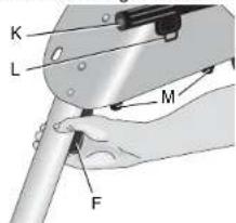
- If the handle (K) has been extended, pull the handle lock (L) down to release the handle and then slide the handle in for storage or saw usage.
TO ATTACH D EWALT DW745 TABLE SAW TO THE SAW MOUNTING BRACKETS
- Remove the front feet bolts and the front rubber feet from the DW745 table saw.
- Remove the rear feet from the rear frame bar of the saw.
- Retain these components for future use.
text_image
K L E- Feed a hex head bolt with flat washer installed through each of the four holes in the frame bars where the removed front and rear feet were previously installed. Secure each location with a flat washer, lock washer and nut provided.
⚠ WARNING: To reduce the risk of personal injury, NEVER use the table saw with the handle extended. An extended handle creates an unsafe work area.
▲WARNING: To reduce the risk of personal injury, do not hang objects from the handle. The stand may tip when downward force is applied.
Transporting the Saw on the Stand COLLAPSING THE STAND FOR TRANSPORT
- Place one hand under the leg support and hold the legs slightly off the ground.
- Depress the leg release lever (F) with the other hand then push the leg under the beam on the stand. Repeat the operation on the second leg of the stand and rest the stand on wheels.
text_image
K L M F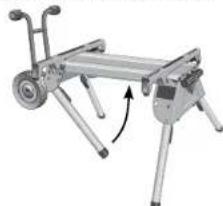
natural_image
Mechanical device with articulated legs and a curved arrow indicating rotation (no text or symbols)- Repeat with the other end of the stand.
- Pull the extendable handle (K) out of the side of the stand. The spring-loaded handle lock (L) will lock the handle into position for
transporting the saw on the stand. Pull the handle lock down to release the handle and then slide the handle in for storage. ▲WARNING: To reduce the risk of personal injury, DO NOT operate the table saw mounted to the stand with the legs folded and the stand sitting on the ground.
To Raise Stand from Collapsed Position Roll the stand to the workspace. Be sure the area is flat and stable before attempting to set up the saw and stand.
- Tilt up the stand until the saw is at a 90 degree angle.
- Depress the leg release levers one at a time to release the locking pins and pull the front legs out until each locking pin clicks into the detent.
⚠ WARNING: Be sure that the locking pins have engaged and the legs are firmly held in place. - Rest the stand on the legs.
- Depress the handle lock to release the handle. Slide the handle into the leg support for storage as you work.
- Go to the opposite side of the stand and grasp the saw under the rear axle. Lift the saw and stand.
- Reach under the stand and, one at a time, depress the leg release levers to release the locking pins. Pull out the remaining two legs. Be sure that the locking pins have engaged and the legs are firmly held in place. Rest the stand on the ground.
Accessories
▲WARNING: Since accessories, other than those offered by DEWALT, have not been tested with this product, use of such accessories with this tool could be hazardous. To reduce the risk of serious injury, place stand on flat, stable surface. DO NOT create unstable conditions.
Recommended accessories for use with your tool are available at extra cost from your local dealer or authorized service center. If you
need assistance in locating any accessory, please contact DEWALT Industrial Tool Co., 701 East Joppa Road, Baltimore, MD 21286, call 1-800-4-DEWALT (1-800-433-9258) or visit our website www.dewalt.com.
Repairs
To assure product SAFETY and RELIABILITY, repairs, maintenance and adjustments should be performed by a DEWALT factory service center, a DEWALT authorized service center or other qualified service personnel. Always use identical replacement parts.
Three Year Limited Warranty
DEWALT will repair, without charge, any defects due to faulty materials or workmanship for three years from the date of purchase. This warranty does not cover part failure due to normal wear or tool abuse. For further detail of warranty coverage and warranty repair information, visit www.dewalt.com or call 1-800-4-DEWALT (1-800-433-9258). This warranty does not apply to accessories or damage caused where repairs have been made or attempted by others. This warranty gives you specific legal rights and you may have other rights which vary in certain states or provinces.
In addition to the warranty, DEWALT tools are covered by our:
1 YEAR FREE SERVICE
DEWALT will maintain the tool and replace worn parts caused by normal use, for free, any time during the first year after purchase.
90 DAY MONEY BACK GUARANTEE
If you are not completely satisfied with the performance of your DEWALT Power Tool, Laser, or Nailer for any reason, you can return it within 90 days from the date of purchase with a receipt for a full refund – no questions asked.
LATIN AMERICA: This warranty does not apply to products sold in Latin America. For products sold in Latin America, see country specific warranty information contained either in the packaging, call the local company or see website for warranty information.
FREE WARNING LABEL REPLACEMENT: If your warning labels become illegible or are missing, call 1-800-4-DEWALT for a free replacement.
text_image
DW7440RS TABLE BAND STAND FRONT A. 2013 WALWALSHI WALWALSHI: A BANDER FOR THE YEAR 1985 (COWA) AND THE BANANA LEAFY OF THE COLDEN EARTH OF THE LIME OF THE COLDEN EARTH OF THE LIME OF THE COLDEN EARTH OF THE LIME OF THE COLDEN EARTH OF THE LIME OF THE COLDEN EARTH OF THE LIME OF THE COLDEN EARTH OF THE LIME OF THE COLDEN EARTH OF THE LIME OF THE COLDEN EARTH OF THE LIME OF THE COLDEN EARTH OF THE LIME OF THE COLDEN EARTH OF THE LIME of THE COLDEN EARTH OF THE LIME OF THE COLDEN EARTH OF THE LIME OF THE COLDEN EARTH OF THE LIME OF THE COLDEN EARTH OF THE LIME OF THE COLDEN EARTH OF THE LIME OF THE COLDEN EARTH OF THE LIME OF THE COLDEN EARTH OF THE LIME OF THE COLDEN EARTH OF THE LIME OF THE COLDEN EARTH OF THE LIME OF The COLDEN EARTH OF THE LIME OF THE COLDEN EARTH OF THE LIME OF THE COLDEN EARTH OF THE LIME OF THE COLDEN EARTH OF THE LIME OF THE COLDEN EARTH OF THE LIME OF THE COLDEN EARTH OF THE LIME OF THE COLDEN EARTH OF THE LIME OF THE COLDEN EARTH OF THE LIME OF THE COLDEN EARTH OF THE LIME OF THE TCAE A. 2013 WALWALSHI WALWALSHI: A BANDER FOR THE YEAR 1985 (COWA) AND THE BANANA LEAFY OF THE COLDEN EARTH OF THE LIME OF THE COLDEN EARTH OF THE LIME OF THE COLDEN EARTH OF THE LIME OF THE COLDEN EARTH OF THE LIME OF THE COLDEN EARTH of THE LIME OF THE COLDEN EARTH OF THE LIME OF THE COLDEN EARTH OF THE LIME OF THE COLDEN EARTH OF THE LIME OF THE COLDEN EARTH OF THE LIME OF THE COLDEN EARTH OF THE LIME OF THE COLDEN EARTH OF THE LIME OF THE COLDEN EARTH OF THE LIME OF THE COLDEN EARTH OF THE LIME OF THE COLDEN EARTH OF THEY A. 2013 WALWALSHI WALWALSHI: A BANDER FOR THE YEAR 1985 (COWA) AND THE BANANA LEAFY OF THE COLDEN EARTH OF THE LIME OF THE COLDEN EARTH OF THE LIME OF THE COLDEN EARTH OF THE LIME OF THE COLDEN EARTH OF THE LIME OF THE COLDEN EARTH ON A. 2013 WALWALSHI WALWALSHI: A BANDER FOR HEATHE LEAFY OF THE YEAR 1985 (COWA) AND HEATHE LEAFY OF THE YEAR 1985 (COWA) AND HEATHE LEAFY OF HEATHE LEAFY OF THE YEAR 1985 (COWA) AND HEATHE LEAFY OF HEATHE LEAFY OF HEATHE LEAFY A. 2013 WALWALSHI WALWALSHI: A BANDER FOR HEATHE LEAFY OF THE YEAR 1985 (COWA) AND HEATHE LEAFY OF HEATHE LEAFY OF THE YEAR 1985 (COWA) AND HEATHE LEAFY OF HEATHE LEAFY A. 2013 WALWALSHI WALWALSHI: A BANDER FOR HEATHE LEAFY OF THE YEAR 1985 (COWA) AND HEATHE LEAFY OF HEATHE LEAFY OF THE YEAR 1985 (COWA) AND HEATHE LEAFY OF HEATHE LEAVES A. 2013 WALWALSHI WALWALSHI: A BANDER FOR HEATHE LEAFY OF THE YEAR 1985 (COWA) AND HEATHE LEAFY OF HEATHE LEAVES A. 2013 WALWALSHI WALWALSHI: A BANDER FOR HEATHE LEAFY OF THE YEAR 1985 (COWA) AND HEATHE LEAVES A. 2013 WALWALSHI WALWALSHI: A BANDER FOR HEATHE LEAVES A. 2013 WALWALSHI WALWALSHI: A BANDER FOR HEATHE LEAVES A. 2013 WALWALSHI WALWALSHI: A BANDER FOR HEATHE LEAVES A. 2013 WALWALSHI WALWALSHI: A BANGEL LEAFY OF THE YEAR 1985 (COWA) AND HEATHE LEAFY OF HEATHE LEAVES A. 2013 WALWALSHI WALWALSHI: A BANGEL LEAFY OF HEATHE LEAVES A. 2013 WALWALSHI WALWALSHI: A BANGEL LEAFY OF HEATHE LEAVES A. 2013 WALWALSHI WALWALSHI: A BANGEL LEAFY OF HEATHE LEAVES A. 2013 WALWALSHIDW7440RS
text_image
Technical diagram showing mechanical assembly steps with labeled parts B and Cnatural_image
Illustration of two hands operating a mechanical device (no text or symbols visible)natural_image
Mechanical device with a cutting tool and mounting base (no visible text or symbols)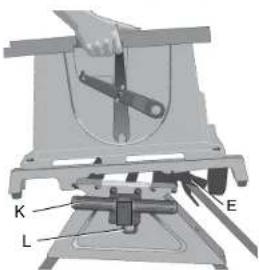
text_image
K L Etext_image
Technical diagram of a wheeled cart with labeled components including wheels, wheels, and guide rails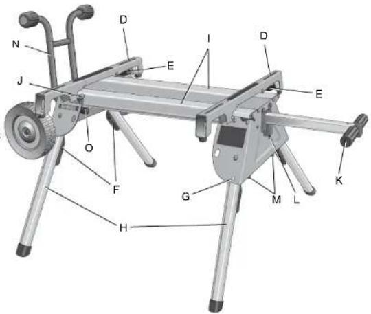
text_image
N J O F H G M L K E D I D Etext_image
cios B A C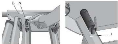
text_image
B N Inatural_image
Illustration of a hand holding a tool labeled 'M' over a mechanical component (no text or symbols present)text_image
Technical diagram of a mechanical clamp or bracket assembly with labeled parts D and Enatural_image
Illustration of a hand holding a small object with a circular mark on the palm, next to a device (no text or symbols visible)text_image
DW744RS TABLE LAW SAW 7.1 FRONT A WARRIANT SALADY, TOWA, MAULIN, MAULIN, MAULIN, MAULIN, MAULIN, MAULIN, MAULIN, MAULIN, MAULIN, MAULIN, MAULIN, MAULIN, MAULIN, MAULIN, MAULIN, MAULIN, MAULIN, MAULIN, MAULIN, MAULIN, MAULIN, MAULIN, MAULIN, MAULIN, MAULIN, MAULINA SALADY, TOWA, MAULIN, MAULIN, MAULIN, MAULIN, MAULIN, MAULIN, MAULIN, MAULIN, MAULIN, MAULIN, MAULIN, MAULIN, MAULIN, MAULIN, MAULIN, MAULIN, MAULIN, MAULIN, MAULIN, MAULIN, MAULIN, MAULIN, MAUMLA SALADY, TOWA, TOWA, MAULIN, MAULIN, MAULIN, MAULIN, MAULIN, MAULIN, MAULIN, MAULIN, MAULIN, MAULIN, MAULIN, MAULIN, MAULIN, MAULIN, MAULIN, MAULIN, MAULIN, MAULIN, MAULIN SALADY, TOWA, TOWA, TOWA, TOWA, TOWA, TOWA, TOWA, TOWA, TOWA, TOWA, TOWA, TOWA, TOWA, TOWA, TOWA SALADY, TOWA, TOWA, TOWA, TOWA, TOWA, TOWA, TOWA, TOWA, TOWA, TOWA, TOWA SALADY, TOWA, TOWA, TOWA, TOWA, TOWA, TOWA, TOWA, TOWA SALADY, TOWA SALADY SALADY SALADY SALADY SALADY SALADY SALADY SALADY SALADY SALADY SALADY SALADY SALADY SALADY SALADY SALADY SALADY SALADY SALADY SALADY SALAD Y SALAD Y SALAD Y SALAD Y SALAD Y SALAD Y SALAD Y SALAD Y SALAD Y SALAD Y SALAD Y SALAD Y SALAD Y SALAD Y SALAD Y SALAD Y SALAD Y SALAD Y SALAD Y SALAD Y SALAD A SALAD A SALAD A SALAD A SALAD A SALAD A SALAD A SALAD A SALAD A SALAD A SALAD A SALAD A SALAD A SALAD A SALAD A SALAD A SALAD A SALAD A SALAD A SALAD A SALAD B SALAD B SALAD B SALAD B SALAD B SALAD B SALAD B SALAD B SALAD B SALAD B SALAD B SALAD B SALAD B SALAD B SALAD B SALAD B SALAD BDEWALT Industrial Tool Co., 701 East Joppa Road, Baltimore, MD 21286 (AUG09) Part No. N044470 DW7440RS
Copyright © 2007, 2008, 2009 DEWALT
The following are trademarks for one or more DEWALT power tools: the yellow and black color scheme; the "D" shaped air intake grill; the array of pyramids on the handgrip; the kit box configuration; and the array of lozenge-shaped humps on the surface of the tool.