SCCB5394P - Soundbar SAMSUNG - Free user manual and instructions
Find the device manual for free SCCB5394P SAMSUNG in PDF.
User questions about SCCB5394P SAMSUNG
0 question about this device. Answer the ones you know or ask your own.
Ask a new question about this device
Download the instructions for your Soundbar in PDF format for free! Find your manual SCCB5394P - SAMSUNG and take your electronic device back in hand. On this page are published all the documents necessary for the use of your device. SCCB5394P by SAMSUNG.
USER MANUAL SCCB5394P SAMSUNG
Vari-focal Anti-Vandal Dome Camera User's Guide
SCC-B5394/5395
Safety Precautions

This symbol indicates high voltage is present inside. It is dangerous to make any kind of contact with any inside part of this product.

This symbol alerts you that important literature concerning operation and maintenance has been included with this product.
To prevent damage which may result in fire or electric shock hazard, do not expose this appliance to rain or moisture.
WARNING
- Be sure to use only the standard adapter that is specified in the specification sheet. Using any other adapter could cause fire, electrical shock, or damage to the product
-
Incorrectly connecting the power supply or replacing battery may cause explosion, fire, electric shock, or damage to the product.
-
Do not connect multiple cameras to a single adapter. Exceeding the capacity may cause abnormal heat generation or fire.
- Securely plug the power cord into the power receptacle. Insecure connection may cause fire.
- When installing the camera, fasten it securely and firmly. A falling camera may cause personal injury.
- Do not place conductive objects (e.g. screwdrivers, coins, metal things, etc.) or containers filled with water on top of the camera. Doing so may cause personal injury due to fire, electric shock, or falling objects.
- Do not install the unit in humid, dusty, or sooty locations. Doing so may cause fire or electric shock.
-
If any unusual smells or smoke come from the unit, stop using the product. In such case, immediately disconnect the power source and contact the service center. Continued use in such a condition may cause fire or electric shock.
-
If this product fails to operate normally, contact the nearest service center. Never disassemble or modify this product in any way. (SAMSUNG is not liable for problems caused by unauthorized modifications or attempted repair.)
- When cleaning, do not spray water directly onto parts of the product. Doing so may cause fire or electric shock.
CAUTION
- Do not drop objects on the product or apply strong shock to it. Keep away from a location subject to excessive vibration or magnetic interference.
- If you want to relocate the already installed product, be sure to turn off the power and then move or reinstall it.
- Remove the power plug from the outlet when then there is a lightning. Neglecting to do so may cause fire or damage to the product.
- Keep out of direct sunlight and heat radiation sources. It may cause fire.
- Install it in a place with good ventilation.
- Avoid aiming the camera directly towards extremely bright objects such as sun, as this may damage the CCD image sensor.
-
Apparatus shall not be exposed to dripping or splashing and no objects filled with liquids, such as vases, shall be placed on the apparatus.
-
The Mains plug is used as a disconnect device and shall stay readily operable at any time.
FCC Statement
This device complies with part 15 of the FCC Rules. Operation is subject to the following two conditions:
1) This device may not cause harmful interference, and
2) This device must accept any interference received including interference that may cause undesired operation.
Note
This equipment has been tested and found to comply with the limits for a Class A digital device, pursuant to part 15 of FCC Rules. These limits are designed to provide reasonable protection against harmful interference when the equipment is operated in a commercial environment. This equipment generates, uses, and can radiate radio frequency energy and, if not installed and used in accordance with the instruction manual, may cause harmful interference to radio communications. Operation of this equipment in a residential area is likely to cause harmful interference in which case the user will be required to correct the interference at his own expense.
Important Safety Instructions
- Read these instructions.
- Keep these instructions.
- Heed all warnings.
- Follow all instructions.
- Do not use this apparatus near water.
- Clean only with dry cloth.
- Do not block any ventilation openings. Install in accordance with the manufacturer's instructions.
- Do not install near any heat sources such as radiators, heat registers, or other apparatus (including amplifiers) that produce heat.
- Do not defeat the safety purpose of the polarized or grounding-type plug. A polarized plug has two blades with one wider than the other. A grounding type plug has two blades and a third grounding prong. The wide blade or the third prong is provided for your safety. If the provided plug does not fit into your outlet, consult an electrician for replacement of the obsolete outlet.
- Protect the power cord from being walked on or pinched particularly at plugs, convenience receptacles, and the point where they exit from the apparatus.
- Only use attachments/accessories specified by the manufacturer.
-
Use only with cart, stand, tripod, bracket, or table specified by the manufacturer, or sold with the apparatus.
-
Unplug this apparatus. When a cart is used, use caution when moving the cart/apparatus combination to avoid injury from tip-over.
- Refer all servicing to qualified service personnel. Servicing is required when the apparatus has been damaged in any way, such as power-supply cord or plug is damaged, liquid has been spilled or objects have fallen into the apparatus, the apparatus has been exposed to rain or moisture, does not operate normally, or been dropped.
Contents
Overview 6
About this guide 6
Product overview 6
Main features 6
Components 7
Checking components in the package 7
Components of your camera 8
Installation 9
Setting switches 9
Setting function switches 9
Connecting cables and changing the settings 11
Installing camera 12
Before installation 12
About the installation holes 12
Installing on a pipe 13
Installing the camera on the ceiling 15
Disassembling/assembly the Main body from the Case 16
Adjusting the camera direction 17
Appendix A: Specifications for NTSC Standard 19
Appendix B: Specifications for PAL Standard 20
Overview
About this guide
This user guide includes basic instructions for the product. It is recommended that all users read this guide before use.
This guide is divided as follows:
Chapter 1, "Overview," introduces the user guide and product related information. (This chapter)
Chapter 2, "Installation," explains how to set and install the product.
Appendix, "Specifications," provides the specifications of the product.
Product overview
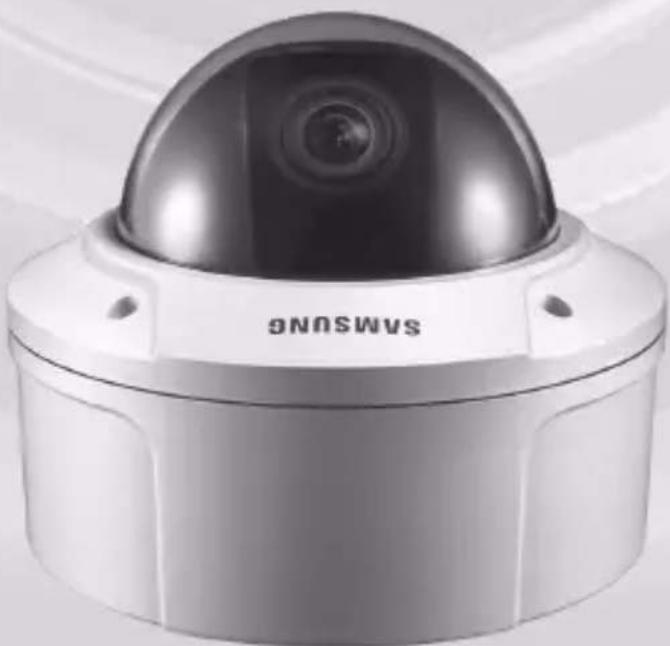
This anti-vandal dome camera provides the superb monitoring features in bank and business areas and it is a water-proof and vibration-proof camera, which can strongly endure an external impact. This vari-focal camera provides the digital noise reduction (DNR) and real-time CCD defect correction features for implementing a clear image.
Main features
Power: DC 12V/AC 24V
Special functions
Line lock (LL) control
- Auto white balancing
Horizontal/vertical image reversing
- Flickerless control
- Low shutter speed control
- Backlight compensation control
Automatic switching between color and black & white modes
- Equipped with vari-focal lens
- Auto Iris function
- Digital noise reduction (DNR)
Dynamic CCD defect compensation

Components
Checking components in the package
Please check your camera and accessories are included in the package. Those components are as shown below:
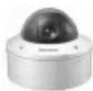
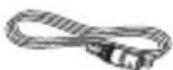

Camera Test Monitor Cable User's Guide
| Image Part | name Standard Quantity Usage | |||
| Plastic anchor HUD 5 4 (EA) | Attach each piece to screw connection holes for strengthening connection | |||
| ASSY screw machine | BH M5 X L6. (White+o-ring) | 8 | Used for filling in the holes when installing pipe and wall mount | |
| ASSY screw tapping | TH M4xL30 (Black+ o-ring) | 4 | Used when installing your camera on the ceiling or wall | |
| L-Wrench TROX T-20 1 | Used for assembling/ disassembling the Dome cover | |||
| Template 1 Used for guiding the installation | ||||
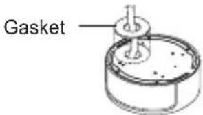
| Gasket-pipe hole T2.5 W56 1 | Used to make a wiring hole when installing the camera on the ceiling or wall | |||
Note
The test monitor cable is used to test the camera by connecting to a portable display. If you really want to connect the camera to a monitoring display, use the BNC cable.
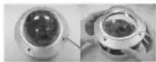
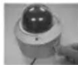
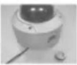
Components of your camera
Your camera has the following components:
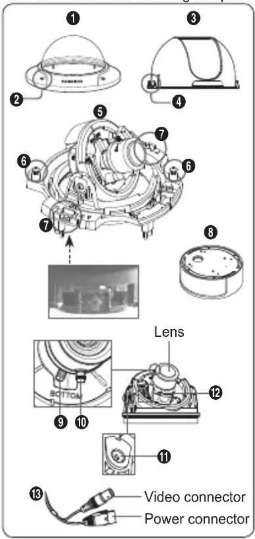
- Dome cover: Covers the inner cover, lens, and main body to protect them.
- Cover screw: Use it to assemble or disassemble both dome cover and case.
- Inner cover : Covers the main body to protect it.
- Wing locker: Push a long thin screwdriver into its narrow spot and press it outward when you want to remove the inner cover.
- Main body: Includes a lens, a switch board, a PCB board, screws, and such.
- Screws for assembly and disassembly: Using these 2 screws, the Main body is closely connected to the Case.
- Hooker: By pulling the left/right levers in the arrow direction, the Main body can be detached from the Case.
- Case: Used as a ceiling or wall fixture. It is fixed using four screws provided in the package.
- Zoom lever: Using this lever, the lens zoom can be adjusted and fixed.
- Focus lever: Using this lever, the lens focus can be adjusted and fixed.
- Tilt fixing screw: Using this screw, the slope of the lens can be adjusted and fixed.
- Switch board Includes two kinds of control switches such as function switches and phase-control switches. The board has eight function switches in the middle and two phase-control buttons on each side of the function switch area.
- Cable: Connect the Video connector to BNC cable and Power connector to power adapter.
Installation
Setting switches
Setting function switches
To set the available functions on your camera, adjust eight switches as shown below:
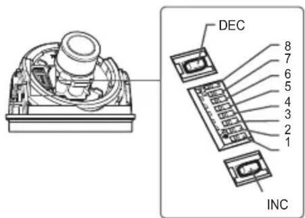
| No | Name | Brief description |
| 1 | LL | Line lock ON/OFF |
| 2 | LSS | Sens-up or Low speed shutter ON/OFF |
| 3 | H-REV | Horizontal reverse ON/OFF |
| 4 | V-REV | Vertical reverse ON/OFF |
| 5 | BLC | Backlight compensation ON/OFF |
| 6 | FL | Flickerless ON/OFF |
| 7 | D/N | Automatic switching between color and black & white ON/OFF |
| 8 | AWB | Automatic white balance ON/OFF |
- Switch 1 (LL): When this switch is set to OFF, the camera operates in the internal synchronization mode, while when it is set to ON, the camera operates in the line lock mode.
In the internal synchronization mode, the camera always uses an inside crystal oscillator for synchronization. However if multiple cameras are connected to a sequential switcher, picture rolling or flickering may occur when switching from one camera to another. In this case, you can set this switch to ON to solve this problem.
The line lock mode allows the camera to use the phase of the AC power as the synchronization reference. In this mode, you can use the phase control buttons(INC/DEC).
Note
When you are using the DC 12V power, set this switch to OFF. The line lock feature will not normally operate even when the switch is set to ON.
Set the LL switch to ON while the AC power is connected. If any picture roll happens, you have to adjust the phase using the phase-control buttons. Press the INC or DEC button to increase or decrease the phase by one degree.
- Switch 2 (LSS): This sens-up mode accumulates the image fields in memory to reduce noise but increase the brightness and contrast rate. When this switch is set to ON, the camera automatically switches to a maximum of 128 times of image acquisition speed to implement a clear picture for darker image.
- Switch 3 (H-REV) : When this switch is set to ON, the camera image is reversed horizontally. If you want to monitor your site using a mirror, you can use this feature to see the right image.
- Switch 4 (V-REV) : When this switch is set to ON, the camera image is reversed vertically. If your camera reluctantly displays the vertically reversed image, you can use this feature to see the right image.
-
Switch 5 (BLC): When this switch is set to ON, you can view a clear image even though the camera faces any excessive light such as sunlight and fluorescent light. When it is set to OFF, the subject with excessive light is not clearly shown.
-
Switch 6 (FL): When this switch is set to ON, the shutter speed is fixed to 1/100 sec (for NTSC) or 1/120 sec (for PAL) to prevent screen from flickering by the disacccordance between vertical synchronous frequency (50Hz for NTSC, 60Hz for PAL) and on-andoff frequency of a light.
- Switch 7 (D/N): When this switch is set to ON, the camera automatically switches between color and B&W according to the brightness of the vicinity.
- Switch 8 (AWB): This switch adjusts white balancing. When this switch is set to ON, this camera operates in ATW mode, and in case of OFF, this camera operates in AWC mode.
ATW (Auto Tracking White Balance): The color temperature is automatically adjusted according to the environmental change. (Approx. 2000^ to 11,000^ ) - AWC (Auto White Balance Control): It stores the color temperature just when the switch is changed to OFF. Accordingly color temperatures are adjusted by the stored value.
Caution
- The IRIS setting range for the camera is approximately 80 to 120 IRE. It means the camera does not provide the IRIS full open/close feature but the restricted variation range.
. Use the camera after setting to the proper level (80 IRE or above) because the IRIS hunting may occur when the level is 75 IRE or below.

Connecting cables and changing the settings
Before installing your camera, you have to adjust the lens focus, zoom, and switch settings.
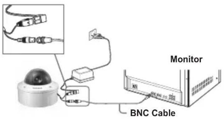
To connect cables
- Connect the BNC cable to the Video connector attached on your camera.
- Connect the BNC cable to the Video Input on a monitor.
- Connect the power adapter to the Power connector attached on your camera. When the monitor is turned on, the camera image appears.
To adjust the lens focus, zoom, and function settings
- Remove the Cover dome and Inner cover. For more details about the removing procedures, see "Installation procedure," in the Installing camera section on the next page.
- Adjust the focus, zoom, and function settings of your camera using the Focus lever, Zoom lever, and Switch board while you are viewing the image on the screen.
- If you want to fix the adjusted focus and zoom, screw up the levers.
Installing camera
Before installation
Before installing your camera, you have to read the following cautions:
You have to check whether the location (ceiling or wall) can bear five times the weight of your camera.
- Don't let the cable to be caught in improper place or the electric line cover to be damaged. Otherwise it may cause a breakdown or fire. You can use wall mount adaptor (SADT-102WM), and pole mount adaptor (SADT-100PM) for installing the camera on the wall or pipeline.
- When installing your camera, don't allow any person to approach the installation site. If you have any valuable things under the place, move them away.
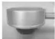
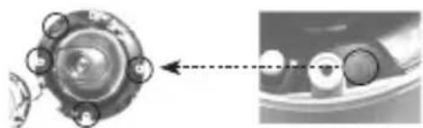
About the installation holes
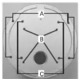
Bottom of camera
A: Use these holes when directly installing your camera on the ceiling or wall.
× While those are not used, fill in the holes using the screw machine (M5 X L6.) for waterproofing.
B: Use four holes when directly installing your camera on the junction box
× You can use the 4 1/8 diameter round type junction box for assembly. (The junction box, gasket, and cover are separately purchased items.)
C: Use these holes when installing the wall mount adapter (SADT-102WM)
× While those are not used, fill in the holes using the screw machine (M5 X L6.) for waterproofing.
The holes that are not used should be tightly sealed up using the screws provided for waterproofing. When the screws don't have rubber rings inside or are not closely attached, note that it can cause waterproofing problem. For attaching screws, see page 16 "Disassembling/assembling the Main body from the Case."

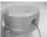
Installing on a pipe
Before installation, you have to be familiar with the above cautions and fill in the holes that are not used for installation.
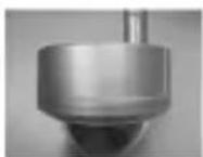
To install your camera bottom on a pipe
- After connecting the power and video cables, throw them inside the pipeline and screw the male thread pipe into the female pipe thread in your camera tightly to fix the Main body. (In this case, be sure to tape with Teflon tape before assembly for waterproofing. Be careful for the wiring cable not to be stuck in the connection area.)
- Attach the Dome cover. (Screw the connection bolts tightly using the L-Wrench for waterproofing.)
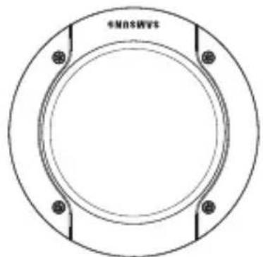
To change the SAMSUNG logo position, move the location of the connection rubber band as show below and rotate for assembly. (The rotation limit is 180 degree.)
- Adjust the angle of the camera in search of a better view.
1) Separate the Dome cover using the L-Wrench provided. (To make loose the screws, rotate counterclockwise.)
2) Adjust the lens direction. For more information, see page 17 "Adjusting the camera direction."

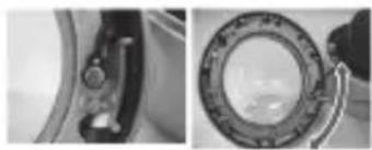
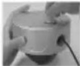
To install the camera side on a pipe
- Pull the power and video cables through the pipe connection hole on the camera side
1) Remove the side cover from the Case using a coin or minus (-) driver. (Rotate counterclockwise.)
2) Push the power and video cables stretched outside of the bottom hole into the Case. And pull them out from the side cover of the Case.
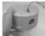
- Attach the removed side cover to the bottom hole and rotate it clockwise using a coin or minus (-) driver. (Be sure to insert the O-ring (P22 T2.4) into the hole before assembly. The ring is necessary for waterproofing.)
- After pulling the power and video cables through the connection pipe, screw the male thread pipe into the female pipe thread in your camera tightly to fix the Main body. (In this case, be sure to tape with Teflon tape before assembly for waterproofing. Be careful for the wiring cable not to be stuck in the connection area.)
-
Adjust the lens direction. For more information, see page 17, "Adjusting the camera direction."
-
Attach the Dome cover. For more information, see step 3 in "To install your camera bottom on a pipe" on page 13.
Installing the camera on the ceiling
Before installation, you have to be familiar with the above cautions and fill in the holes that are not used for installation.
To install your camera bottom on a pipe
- Attach the provided template to the place to be installed and penetrate a hole (5mm diameter, minimum depth 35mm) for fixing your camera to insert the provided plastic anchor (HUD 5) to the full.
- After connecting both power and video cables, put them in order not to have damage during installation.
- Remove the Dome cover. For more information, see step 2 in "To install your camera bottom on a pipe" on page 13.
- Install your camera. After aligning the hole where the plastic anchor is inserted with the camera installation hole, make tight four ASSY screw-tappings where O-rings are inserted. (If no O-rings are inserted, water leak may happen.)
- Adjust the camera lens direction. For more information, see page 17, "Adjusting the camera direction."
- Attach the Dome cover. For more information, see step 3 in "To install your camera bottom on a pipe" on page 13.
In case of wiring after penetrating a hole on the installation site
1 Penetrate a wiring hole toward the pipe. (Recommended hole size: within 30mm diameter)
Attach the gasket on the bottom of the product as shown below. You have to correctly align the hole with the pipe hole.
If the hole deviates from the gasket, water leak may happen.

Disassembling/assembly the Main body from the Case
The holes that are not used should be tightly sealed up using the screws provided for waterproofing. To detach the Main body from the Case, follow the instructions below:
-
- Remove the Dome cover first.
- Detach the Main body of the camera from the Case.
1) Make loose two screws by rotating counterclockwise.
2) Detach the Main body of the camera after unlocking by pulling the left and right levers in the arrow direction.
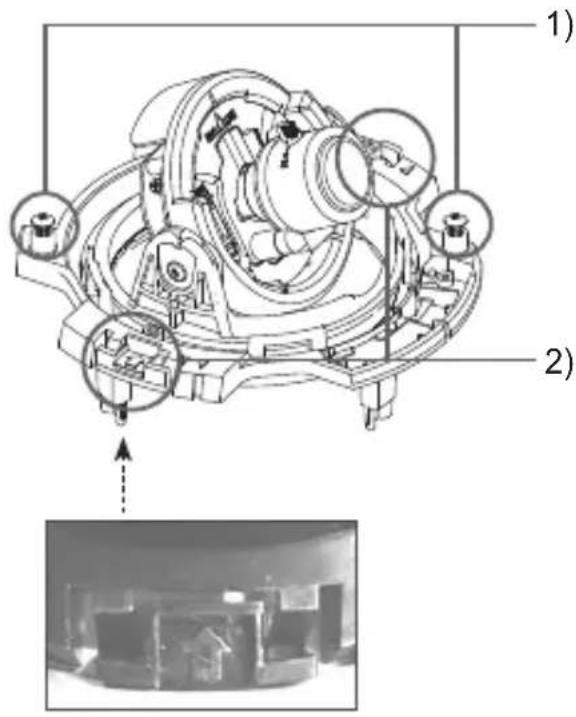
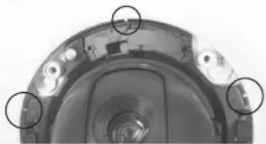
- Assemble the Main body of the camera with the Case. (Align three alignment grooves of the Main body with the bumps of the Case and assemble them.)
- Attach the Dome cover using the L-Wrench. For more information, see step 3 in "To install your camera bottom on a pipe" on page 13.

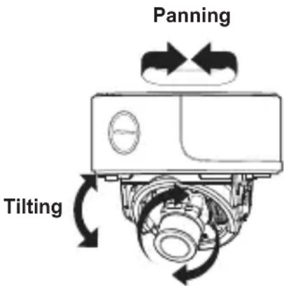
Adjusting the camera direction
When the camera is fixed on the ceiling, you can adjust the camera viewing angle. You can rotate your camera leftward or rightward (Panning), and can change the slope of your camera upward or downward (Tilting).
In case of panning, the rotation limit of your camera is set to 355 degree (100 degree clockwise and 255 degree counterclockwise). The rotation is stopped by the Stopper inside of the camera. For panning control, first unfasten two screws located on the bottom and rotate in the direction you want, and then fasten them to fix the camera.
In case of tilting, you can change the slope of your camera from zero to 90 degree. However if the slope
angle is under 17 degree, you can encounter a partial image hide problem. To fix the location after adjusting the tilting angle, use the Tilt fixing screws.
To adjust the focus and zoom of your camera, use the Zoom lever and Focus lever. When you install the camera on the inclined ceiling or wall, you can rotate the camera lens to see a correct direction image.
Lens rotation
SCC-B539X
Appendix A: Specifications for NTSC Standard
| Item Details | ||||
| Product type CCTV color dome camera | ||||
| Power input AC 24V ± 10% (60Hz ± 0.3 Hz), DC 12V +10%-5% | ||||
| Broadcast type NTSC Standard System (525 Lines, 60 Fields) | ||||
| Power consumption Approx. 1.7W | ||||
| Image device 1/3 inch IT Type Super-HAD CCD | ||||
| Pixels | Total: 811(H) x 508(V), 410,000 pixels Effective: 768(H) x 494(V), 380,000 pixels | |||
| Scanning mode 525 Lines, 2:1 Interlace | ||||
| Scanning line frequency | Horizontal: 15.734Hz(INT)/15.750Hz(LL) Vertical: 59.94Hz(INT)/60Hz(LL) | |||
| Synchronization mode INT/Line Lock (Adjusting the phase using INC/DEC button) | ||||
| Horizontal resolution 540 TV Lines | ||||
| S/N Ratio Approx. 50dB | ||||
| Min. object illumination | SCC-B5395 (Color/BW) | SCC-B5394 (Color/BW) | ||
| F1.2 | Sens-up Off | 50IRE 0.4/0.04Lux 0.4/0.4Lux | ||
| 30IRE 0.24/0.024Lux 0.24/0.24Lux | ||||
| 15IRE 0.12/0.012Lux 0.12/0.12Lux | ||||
| Sens-up x128 | 50IRE 0.0031/0.00031Lux | 0.0031/0.0031Lux | ||
| 30IRE 0.0019/0.00019Lux | 0.0019/0.0019Lux | |||
| 15IRE 0.0009/0.00009Lux | 0.0009/0.0009Lux | |||
| Signal output | COMPOSITE Video(1.0 Vp-p, 75ohm, BNC), Test Monitor OUT(1.0 Vp-p, 75ohm, Harness cable) | |||
| Lens | Auto Iris (DC) Focal length: 2.9 ~ 10.0mm Aperture ratio: 1.2 | |||
| PAN function | Range: 0 to 355° (100 degree clockwise and 255 degree counterclockwise) | |||
| TILT function | Range: 0 to 90° | |||
| Controls | Line Lock (LL) Sens-Up; Low Speed Shutter(LSS) Horizontal Reverse (H-REV) Vertical Reverse (V-REV) Backlight compensation (BLC) Flickerless (FL) Switching between color and B&W modes (D/N) Auto white balancing (AWB) Digital noise reduction (DNR) Dynamic CCD defect compensation | |||
| Operation temperature | -10°C to +50°C | |||
| Operation humidity | Up to 90% | |||
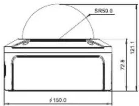
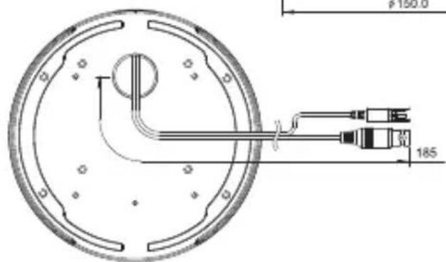
| Size | 150(Ø) x 121(H)mm | |||
| Weight | SCC-B539X: 1.1kg | |||
Appendix B: Specifications for PAL Standard
| Item Details | |||||
| Product type CCTV color | dome camera | ||||
| Power input AC 24V ± 10% (50Hz ± 0.3 Hz), DC 12V +10%/-5% | |||||
| Broadcast type PAL Standard System (625 Lines, 50 Fields) | |||||
| Power consumption Approx. 1.7W | |||||
| Image device 1/3 inch IT | Type Super-HAD CCD | ||||
| Pixels | Total: 795(H) x 596(V), 470,000 pixels Effective: 752(H) x 582(V), 440,000 pixels | ||||
| Scanning mode 625 Lines, 2:1 Interlace | |||||
| Scanning line frequency | Horizontal: 15.625Hz(INT)/15.625Hz(LL) Vertical: 50Hz(INT)/50Hz(LL) | ||||
| Synchronization mode INT/Line Lock (Adjusting the phase using INC/DEC button) | |||||
| Horizontal resolution 540 TV Lines | |||||
| S/N Ratio Approx. 50dB | |||||
| Min. object illumination | SCC-B5395 (Color/BW) | SCC-B5394 (Color/BW) | |||
| F1.2 | Sens-up Off | 50IRE 0.4/0.04Lux 0.4/0.4Lux | |||
| 30IRE | 0.24/0.024Lux 0.24/0.24Lux | ||||
| 15IRE | 0.12/0.012Lux 0.12/0.12Lux | ||||
| Sens-up x128 | 50IRE | 0.0031/0.00031Lux | 0.0031/0.0031Lux | ||
| 30IRE | 0.0019/0.00019Lux | 0.0019/0.0019Lux | |||
| 15IRE | 0.0009/0.00009Lux | 0.0009/0.0009Lux | |||
| Signal output | COMPOSITE Video(1.0 Vp-p, 75ohm, BNC), Test Monitor OUT(1.0 Vp-p, 75ohm, Harness cable) | ||||
| Lens | Auto Iris (DC) Focal length: 2.9 ~ 10.0mm Aperture ratio: 1.2 | ||||
| PAN function | Range: 0 to 355° (100 degree clockwise and 255 degree counterclockwise) | ||||
| TILT function | Range: 0 to 90° | ||||
| Controls | Line Lock (LL) Sens-Up; Low Speed Shutter(LSS) Horizontal Reverse (H-REV) Vertical Reverse (V-REV) Backlight compensation (BLC) Flickerless (FL) Switching between color and B&W modes (D/N) Auto white balancing (AWB) Digital noise reduction (DNR) Dynamic CCD defect compensation | ||||
| Operation temperature | -10°C to +50°C | ||||
| Operation humidity | Up to 90% | ||||
| Size | 150(Ø) x 121(H)mm | ||||
| Weight | SCC-B539X: 1.1kg | ||||

Correct Disposal of This Product
(Waste Electrical & Electronic Equipment)
(Applicable in the European Union and other European countries with separate collection systems)
This marking shown on the product or its literature, indicates that it should not be disposed with other household wastes at the end of its working life. To prevent possible harm to the environment or human health from uncontrolled waste disposal, please separate this from other types of wastes and recycle it responsibly to promote the sustainable reuse of material resources.
Household users should contact either the retailer where they purchased this product, or their local government office, for details of where and how they can take this item for environmentally safe recycling.
Business users should contact their supplier and check the terms and conditions of the purchase contract. This product should not be mixed with other commercial wastes for disposal.
SAMSUNG
SAMSUNG
Vari-focal Anti-Vandal Dome Kamera
Benutzerh andbuch
SCC-B5394/5395

Appendix B: Specifications for PAL Standard
| Madde Ayrintilar | ||||
| Ürün tipi CCTV renkli dome me kamera | ||||
| Güç girisi AC 24V ± 10% (50Hz ± 0.3 Hz), DC 12V +10%-5% | ||||
| Yayın tipi NTSC Standart renkli system (625 hat, 50 alan) | ||||
| Güç tüketimi Yakkışık 1.7W | ||||
| Göruntü cihazı 1/3 incı NT tipi Süper-HAD CCD | ||||
| Piksel | Toplam: 795(Y) x 596(D), 470,000 pikselGeçerli: 752(Y) x 582(D), 440,000 piksel | |||
| Tarama modu 625 hat, 2:1 ara birim | ||||
| Taranan hat frekansi | Yatay: 15.625Hz(INT)/15.625Hz(LL)Dikey: 50Hz(INT)/50Hz(LL) | |||
| Senkronizasyon modu INT/hat Kilidi (INC/DECDMI kullanırear faz ayarlama) | ||||
| Yatay;cüzünürlük 540 TVhatti | ||||
| S/N Orani Yakkışık 50dB | ||||
| Min. object illumination | SCC-B5395 (Renkli/SB) $CC-B5394 (Renkli/SB) | |||
| F1.2 | Sensör-yukari OFF | 50IRE 0.4/0.04 Lux 0.4/0.4 Lux | ||
| 30IRE 0.24/0.024 Lux 0.24/0.24 Lux | ||||
| 15IRE 0.12/0.012 Lux 0.12/0.12 Lux | ||||
| Sensör-yukari x128 | 50IRE 0.0031/0.00031 Lux | 0.0031/0.0031 Lux | ||
| 30IRE 0.0019/0.00019 Lux | 0.0019/0.0019 Lux | |||
| 15IRE 0.0009/0.00009 Lux | 0.0009/0.0009 Lux | |||
| Sinyal;cıkışı | BILESIK Video (1.0 Vp-p, 75ohm, BNC), Test Monitorü OUT (1.0 Vp-p, 75ohm, Donatim kablosu) | |||
| Lens | Oto Iris (DC)Odak uzunluğ: 2.9 ~ 10.0 mmAçiklik orani: 1.2 | |||
| GEZ fonksiyonu | Alan: 0 ila 355° (100 derece saat:yönü ve 255 derece saat:yönünün tersi) | |||
| EGM. fonksiyonu Range: 0 ila 90° | ||||
| Kon controller | Hat kilidi (LL)Sensör-yukari;;dus.dk hiz obtürtur;r (LSS)Yatay:dönme (H-REV)Dikey:dönme (V-REV)Arka işik telafisi (BLC)Titresim (FL)Renkli ve S&B modlariarasinda anahtarlama (D/N)Otomatik beyaz dengeleme (AWB)Dijital gürültu giderme (DNR)Dinamik CCD kusur telafisi | |||
| Çalıstirma sılcılgı | -10°C ila +50°C | |||
| Çalıstirma nemi | %90’a kadar | |||
| Ebat | 150(Ø) x 121(Y)mm | |||
| Ağırkık | SCC-B539X: 1.1kg | |||
SAMSUNG
Part No. AB68-00688D(00)