SCCC4235P - Soundbar SAMSUNG - Free user manual and instructions
Find the device manual for free SCCC4235P SAMSUNG in PDF.
User questions about SCCC4235P SAMSUNG
0 question about this device. Answer the ones you know or ask your own.
Ask a new question about this device
Download the instructions for your Soundbar in PDF format for free! Find your manual SCCC4235P - SAMSUNG and take your electronic device back in hand. On this page are published all the documents necessary for the use of your device. SCCC4235P by SAMSUNG.
USER MANUAL SCCC4235P SAMSUNG
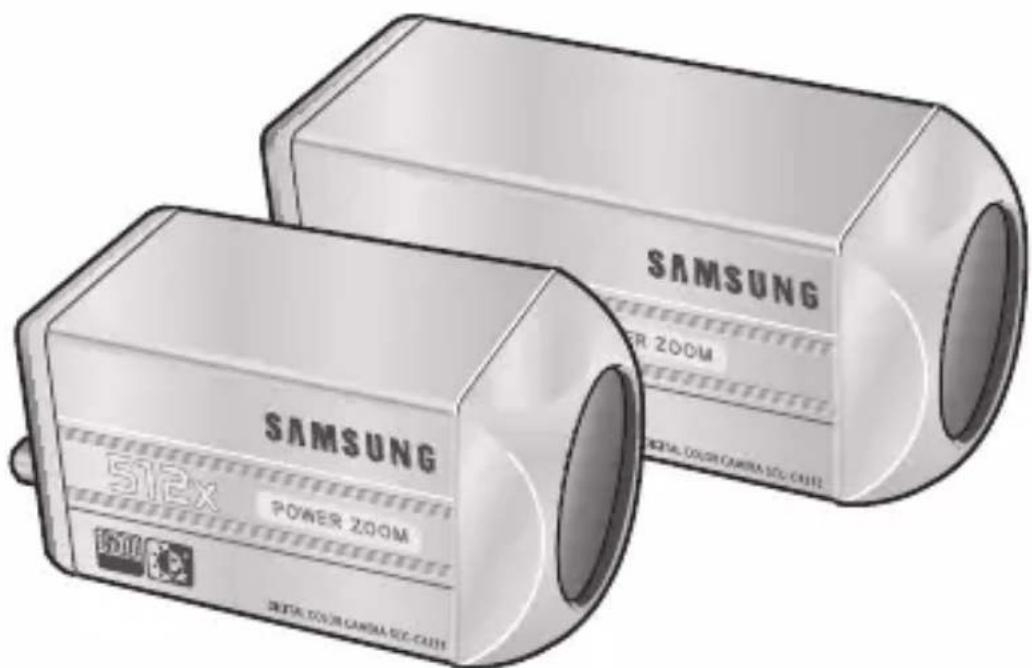
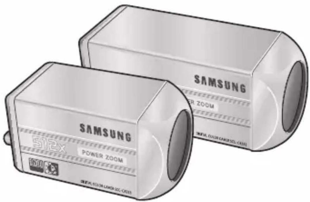
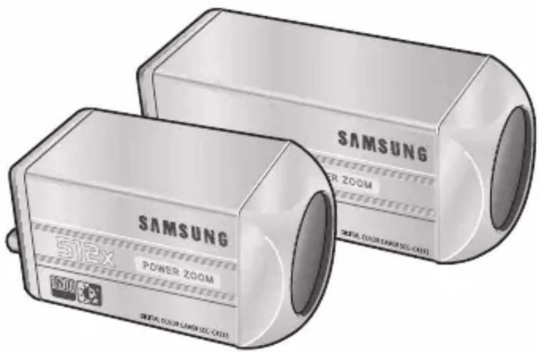
SCC- C4233(P)/C4333(P)/ C4235(P)/C4335(P)
User Manual
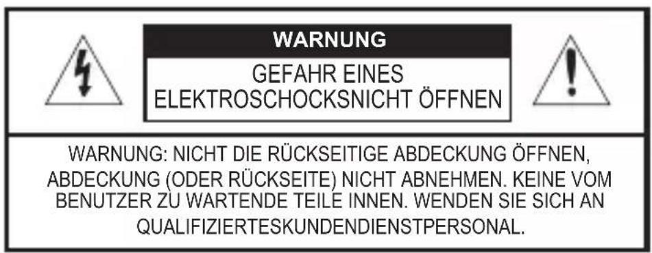
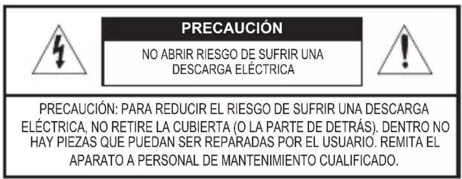
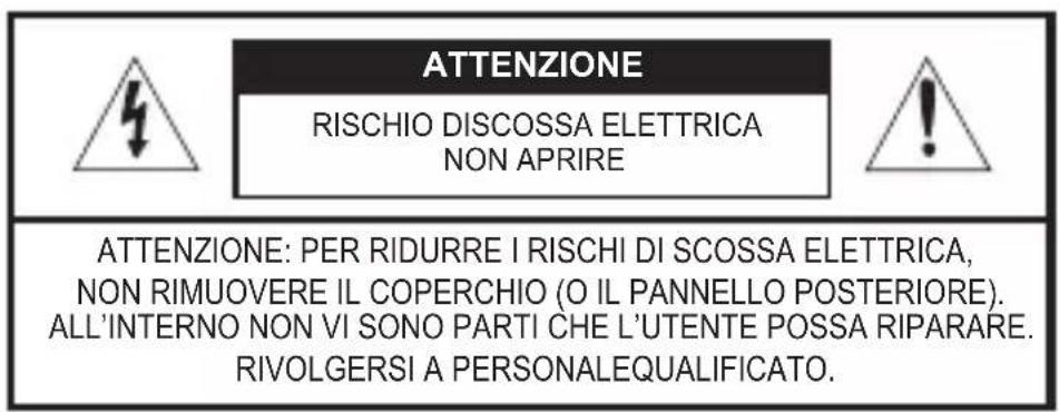
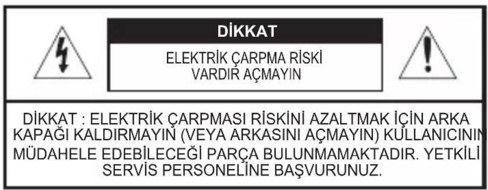
CAUTION
RISK OF ELECTRIC SHOCK. DO NOT OPEN.

CAUTION: TO REDUCE THE RISK OF ELECTRIC SHOCK, DO NOT REMOVE COVER (OR BACK) NO USER-SERVICEABLE PARTS INSIDE REFER SERVICING TO QUALIFIED SERVICE PERSONNEL
This symbol indicates that dangerous voltage consisting a risk of electric shock is present within this unit.

This symbol indicates that there are important operating and maintenance instructions in the literature accompanying this unit.
WARNING
- To reduce the risk of fire or electric shock, do not expose this appliance to rain or moisture.
WARNING
- Be sure to use only the standard adapter that is specified in the specification sheet. Using any other adapter could cause fire, electrical shock, or damage to the product.
- Incorrectly connecting the power supply or replacing battery may cause explosion, fire, electric
shock, or damage to the product.
- Do not connect multiple cameras to a single adapter. Exceeding the capacity may cause abnormal heat generation or fire.
- Securely plug the power cord into the power receptacle. Insecure connection may cause fire.
- When installing the camera, fasten it securely and firmly. A falling camera may cause personal injury.
- Do not place conductive objects (e.g. screwdrivers, coins, metal things, etc.) or containers filled with water on top of the camera. Doing so may cause personal injury due to fire, electric shock, or falling objects.
- Do not install the unit in humid, dusty, or sooty locations. Doing so may cause fire or electric shock.
-
If any unusual smells or smoke come from the unit, stop using the product. In such case, immediately disconnect the power source and contact the service centre. Continued use in such a condition may cause fire or electric shock.
-
If this product fails to operate normally, contact the nearest service centre. Never disassemble or modify this product in any way. (SAMSUNG is not liable for problems caused by unauthorized modifications or attempted repair.)
- When cleaning, do not spray water directly onto parts of the product. Doing so may cause fire or electric shock.
as sun, as this may damage the CCD image sensor.
- Apparatus shall not be exposed to dripping or splashing and no objects filled with liquids, such as vases, shall be placed on the apparatus.
- The Mains plug is used as a disconnect device and shall stay readily operable at any time.
CAUTION
- Do not drop objects on the product or apply strong shock to it. Keep away from a location subject to excessive vibration or magnetic interference.
- Do not install in a location subject to high temperature (over 122^ ), low temperature (below 14^ ), or high humidity. Doing so may cause fire or electric shock.
- If you want to relocate the already installed product, be sure to turn off the power and then move or reinstall it.
- Remove the power plug from the outlet when then there is a lightning. Neglecting to do so may cause fire or damage to the product.
- Keep out of direct sunlight and heat radiation sources. It may cause fire.
- Install it in a place with good ventilation.
- Avoid aiming the camera directly towards extremely bright objects such
Important Safety Instructions
- Read these instructions.
- Keep these instructions.
- Heed all warnings.
- Follow all instructions.
- Do not use this apparatus near water.
- Clean only with dry cloth.
- Do not block any ventilation openings. Install in accordance with the manufacturer's instructions.
- Do not install near any heat sources such as radiators, heat registers, or other apparatus (including amplifiers) that produce heat.
- Do not defeat the safety purpose of the polarized or grounding-type plug. A polarized plug has two blades with one wider than the other. A grounding type plug has two blades and a third grounding prong. The wide blade or the third prong is provided for your safety. If the provided plug does not fit into your outlet, consult an electrician for replacement of the obsolete outlet.
- Protect the power cord from being walked on or pinched particularly at plugs, convenience receptacles, and the point where they exit from the apparatus.
- Only use attachments/accessories specified by the manufacturer.
- Use only with cart, stand, tripod, bracket, or table specified by the manufacturer, or sold with the apparatus.
- Unplug this apparatus. When a cart is used, use caution when moving the cart/apparatus combination to avoid injury from tip-over.
- Refer all servicing to qualified service personnel. Servicing is required when the apparatus has been damaged in any way, such as power-supply cord or plug is damaged, liquid has been spilled or objects have fallen into the apparatus, the apparatus has been exposed to rain or moisture, does not operate normally, or been dropped.24. Wall or Ceiling Mounting – The product should be mounted to a wall or ceiling only as recommended by the manufacturer.
Safety Precautions .... 2
Important Safety
Instructions 4
Overview 6
Special Features 7
Part Names and
Functions 8
Installation 11
Before Installation 11
Checking the contents
of the package 11
Things to keep in mind during
installation and use 11
Installing the Camera ... 12
Power Adapter Cable..... 12
Video Cable 12
Connecting the Cables .. 13
Camera Setup 16
CAMERA ID 17
IRIS 17
WDR. 18
ALC. 18
MANU. 19
SHUTTER 19
AGC 20
MOTION 21
WHITE BAL 21
FOCUS MODE 23
MOTION DET 24
DAY/NIGHT 26
DAY 27
NIGHT 27
AUTO 28
EXT 29
PRIVACY 29
SPECIAL 30
LANGUAGE 31
VIDEO SET 31
RS-485 32
ZOOM SPEED 33
DIGITAL ZOOM 33
DISPLAY ZOOM 34
SYSTEM INFO 34
CTRL TYPE 35
V-SYNC 35
PRESET 36
Product
Specifications 37
Overview
This enriched WDR (Wide Dynamic Range) Day/Night camera can clearly implement both dark and bright parts on the screen with the dual shutter.
When a bright object such as window occupies a part of the screen, it appears white in conventional cameras. But using the state-of-the-art WDR function that this camera provides, you can see the clear image. This Day/Night camera activates the colour mode when in the illumination over the normal value. Otherwise it activates B/W (Black/White) mode by removing the IR cut function, which can improve the sensitivity for identifying objects even in a dark area. It also incorporated the low speed shutter and Sens-Up (Uses the field accumulation method) functions to enhance the low illumination feature.
This camera can be mainly used in the dark places such as basement parking lots under comparatively low illumination. In daytime, it displays the colour screen with a horizontal resolution of 540 lines but at night, it uses the Day/Night feature along with the Sens-Up function to identify objects in a dark area. You can also connect the infrared ray emission equipment to this camera.
Moreover, this camera has more various functions for surveillance. White Balance function that provides accurate colour rendition under any light conditions. Auto Focus function that automatically tracks and focuses on the moving subject. Privacy Zone function to hide a special area for privacy protection. RS485/ Wired remote control function.
Note
SCC-C4233(P)/C4333(P) does not support for WDR function.
SCC-C4233(P)/C4235(P) does not support for V-SYNC function.
High Sensitivity
It implements images of high sensitivity using the up-to-date Super-HAD IT CCD(SCC-C4233(P)/C4333(P))/ExView-HAD PS CCD(SCC-C4235(P)/C4335(P)).
WDR
The WDR function of this camera is the state-of-the-art technology that can effectively enlarge the range for screen gain. It is mainly used for taking photos for window scenes inside a building. Using this technology, you can clearly see both indoor and outdoor images, and can enjoy the excellent picture quality, which is enabled by automatically adjusting the WDR level.
Note
SCC-C4233(P)/C4333(P) does not support for WDR function.
Low Illumination
It uses the digital signal technologies such as low illumination and Day/Night functions that make your camera identify objects even in the worst environment.
Superior Backlight Adjustment
When an object has a bright illumination or sunlight behind it, this camera automatically improves the shaded object picture quality.
Digital Power Synchronization
The full digital Line Lock function directly adjusts the vertical camera synchronization to enhance the operation ability and reliability of this camera.
Note
SCC-C4233(P)/C4235(P) dose not support for Line Lock function.
High Resolution
This camera has realized high resolution of 540 lines using the top-notch full digital image processing and special algorithm technologies.
Output Signal Setting
You can set the following Video output signals: Image reversion (Horizontal, Vertical, or both), Privacy, Horizontal/Vertical profiling, POSI/NEGA function, and digital zooming.
White Balance
It uses to automatically adjust light levels to improve colour balance depending on the illumination.
Auto Focus
It enables to capture clear images by adjusting the automatic focus on the subject movement.

SCC-C4233(P)/C4235(P) SCC-C4333(P)/C4335(P)
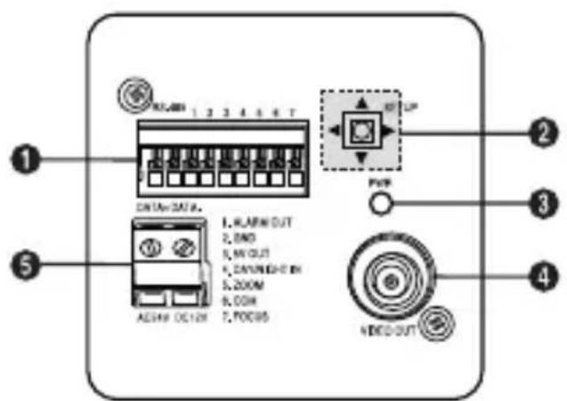
1 Input/Output Connector
This connector has input and output jacks for RS-485 control signals.
RS-485 DATA+
Jack for connection to RS-485 DATA+ signal line.
RS-485 DATA-
Jack for connection to RS-485 DATA- signal line.
1. ALARM OUT
Alarm out jack for motion detection. (Open Collector, On Gnd)
2. GND
Grounding jack.
3.5V OUT
Power supply jack for RS-485 JIG. Use within typical DC +5V 100mA.
4. DAY/NIGHT IN
This is a function to receive the external DAY/NIGHT signal from the sensor(options) and convert the signal into BW.
5-7. ZOOM/ FOCUS REMOTE terminals
This port is used for ZOOM/FOCUS, MENU CONTROL, HOME RETURN, and ONEAF by using an external controller.
Depending on the input condition, 4 modes, A, B, C, and D are available. (SPECIAL - CTRL TYPE)
(Operation Voltage Range: +3V~+13V, -3V~-13V)
1) When the voltage is supplied to either ZOOM or FOCUS port
| Function *1 Code | Tele(Up) | Wide(Down) | Near(Left) Far(Right) |
| ZOOM Port FOCUS Port | |||
| A -6V | +6V -6V +6V | ||
| B -6V | +6V +6V -6V | ||
| C +6V | -6V -6V +6V | ||
| D | +6V -6V +6V -6V | ||
*1: During MENU OFF, controls ZOOM/FOCUS and during MENU ON, changes the direction, Up/Down/Left/Right SETUP switch.
2) When the voltage is supplied to both ports
| Function Code | ENTER/AF *2 HOME | RETURN *3 | ||
| ZOOM Port | FOCUS Port | ZOOM Port | FOCUS Port | |
| A -6V -6V +6V +6V | ||||
| B -6V +6V +6V -6V | ||||
| C +6V -6V -6V +6V | ||||
| D | +6V +6V | -6V -6V | ||
- 2: For short voltage supply during MENU OFF, executes ONEAF and for more than 2 second
- 3: For more than 2 second long voltage supply, moves to the PRESET 0(HOME) position.
2 SETUP Switch
This switch is used to set the function or property. When this switch is pressed for at least 2 seconds, the Setup menu appears.
- [Left/Right] movement or changing the displayed value: By pressing this switch left or right, you can move left or right on the menu or change the displayed value.
- [Up/Down] movement: By pressing this switch up or down, you can move up or down on the menu.
- Setting: When you press this switch in the menu, the selected value or function is confirmed. To enter a submenu, press this button.
Power Display LED
When the power is normally connected, the red LED lights.
4 Video OUT Jack
This is connected to the Video Input jack of the monitor and it outputs the Video signals.
Power Connection Jack
This is connected to the Power cable.
Before Installation
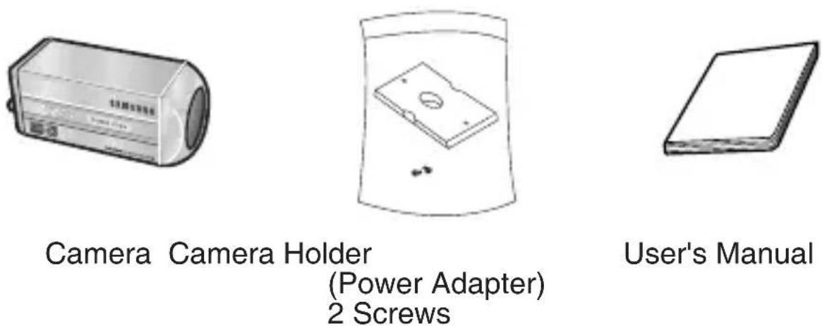
Checking the contents of the package
Make sure that the following items are included in the package.
Things to keep in mind during installation and use
- Do not disassemble the camera on your own.
- Always be careful when handling the camera. Do not strike the camera by your fists or shake it. Please be careful not to be careless when storing and operating it.
- Do not place or operate the camera in any wet environment such as rain or wet surfaces.
- Do not clean the camera with rough sandpaper. Please always use a dry cloth when cleaning it.
- Put the camera in a cool area free from direct sunlight. Otherwise, the camera may be damaged.
Installling the Camera
To install and use the camera, first prepare the following cables.
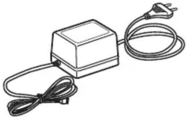
Power Adapter Cable (sold separately)
The requirements for the power adapter, which connects to the camera's POWER IN terminal, are as follows:
- SCC-C4233(P)/C4235(P) : DC 12V 600mA
- SCC-C4333(P)/C4335(P) : AC 24V 300mA
DC 12V 600mA
Video Cable
Use a BNC cable, such as the one shown below, to connect the camera's VIDEO OUT to the monitor.
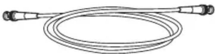
Connecting the Cables
- Connect one end of the BNC cable to the VIDEO OUT.
- Connect the other end of the BNC cable to the VIDEO IN of the monitor.

Video Out Terminal
- Plug in the power adapter. Use a "minus" screwdriver to connect one part of the power adapter, which consists of two lines, to the POWER terminal of the camera as follows:

-
Determine the type of power supply and set the POWER SELECTION switch accordingly. Next, plug the power adapter into a wall outlet.
-
If the camera operates normally, the following screen will be displayed for 5 seconds and then disappears.
SAMSUNG PROTOCOL
ADDRESS 0
TYPE RS-485, HALF
BAUD RATE 9600
ROMVER 1.000
EEPVER 1.000
LENS OK.
-
ROM VER and EEP VER may change without notice.
-
The requirements for RS485 control is as follows :
-
Signaling Speed: 9600 bps
- Data Bit : 8 bits
- Stop Bit : 1 bit
- Parity Bit : none
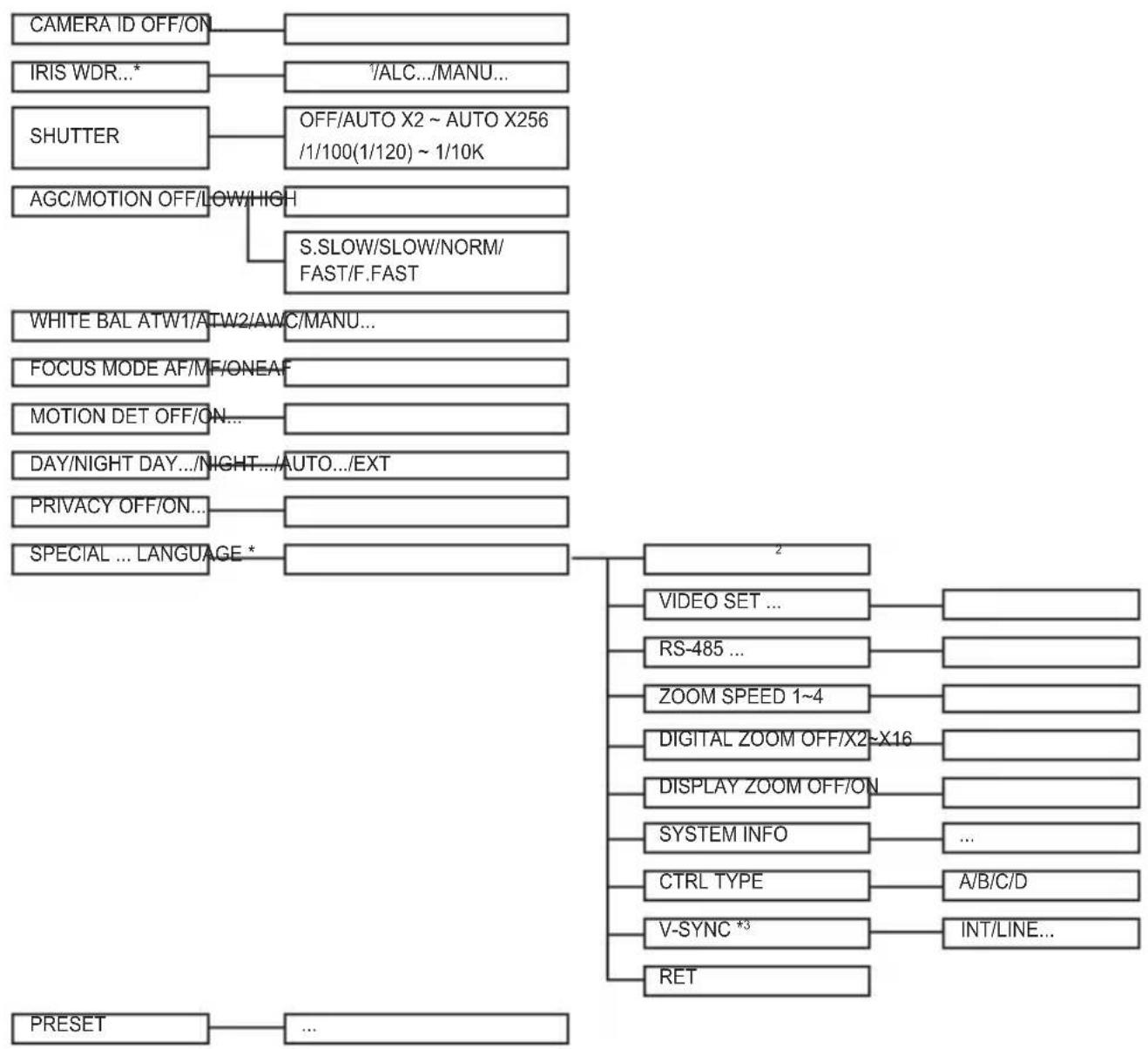
This chapter describes how to configure the camera-related settings. If you press the SETUP switch for at least 2 seconds, the Setup menu appears. The Setup OSD (On-screen Display) map brief is like the following:
Note
1 SCC-C4233(P)/C4333(P) does not support for WDR function.
2 The language may vary depending on sales region.
*3 SCC-C4233(P)/C4235(P) does not support for V-SYNC function.
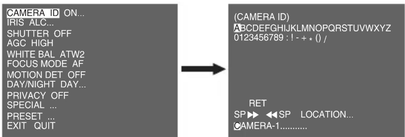
CAMERA ID
The [CAMERA ID] menu is used to assign a camera ID to this camera. If you press the SETUP switch when the [CAMERA ID] menu is selected, the corresponding setup screen appears.
ENG
You can input a camera ID composed of alphabets, numbers, and special characters up to 20 characters long. The input camera ID can be displayed at the desired location when using the [LOCATION...] submenu. When you press the SETUP switch in [RET], the screen returns to the upper menu.
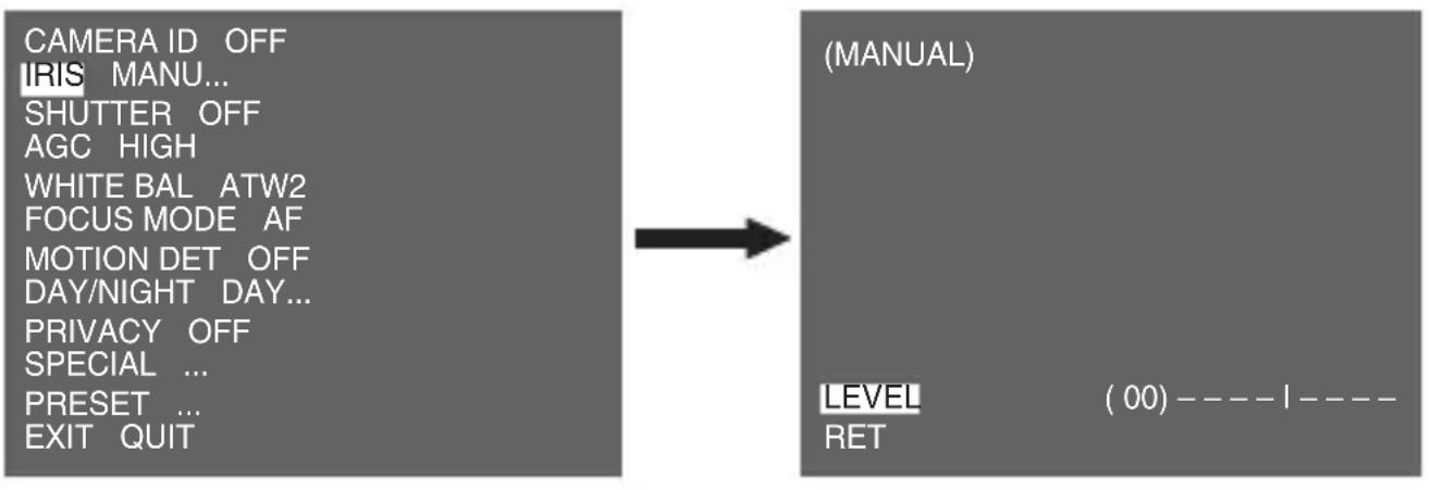
IRIS
The [IRIS] menu is used to set the automatic light control method for this camera.
WDR...
If you press the SETUP switch when the [WDR...] submenu is selected, the corresponding screen appears.
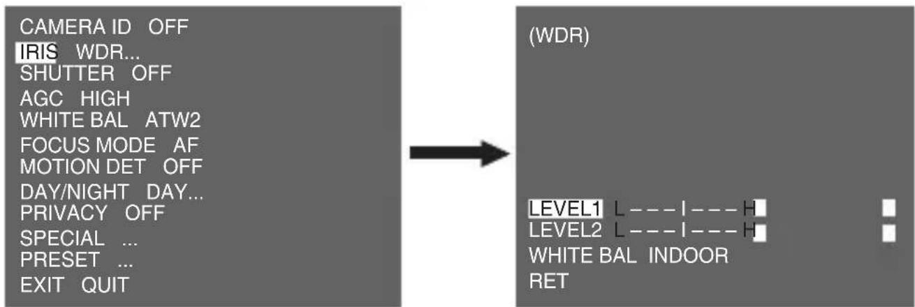
You can adjust the shutter speed in [LEVEL1] and the brightness in [LEVEL2]. You can also select any of [ALL], [OUTDOOR], and [INDOOR] in [WHITE BAL]. In case of [ALL], this camera controls both indoor and outdoor images.
Note
SCC-C4233(P)/C4333(P) does not support for WDR function.
ALC...
If you press the SETUP switch when the [ALC...] submenu is selected, the corresponding screen appears.

You can make the BLC (Back Light Compensation) function active or not. For setting the BLC zone, you can select any of [BOTTOM...], [TOP...], [LEFT...], [RIGHT...], and [CENTER...]. The actual location is displayed when you enter each item.
In case of [USER...], you can set the desired BLC zone by defining the size and location. You can set the Video output level in [LEVEL]. Its selectable range is from -9 to +9.
MANU...
If you press the SETUP switch after selecting MANU in the IRIS item, an additional screen appears in which you can set manually opening or closing the IRIS.
SHUTTER
The [SHUTTER] menu is used to set the high speed electronic shutter and AUTO low speed shutter. The high speed electronic shutter can be used 7 different speeds and is commonly used for imaging fast moving objects. (NTSC: from 1/100 to 1/10K, PAL: from 1/120 to 1/10K). The AUTO low speed electronic shutter can be any of 13 speeds from X2 to X256 and it slows the shutter speed to make images clearer in dark illumination. If you select an AUTO low speed, the shutter speed is automatically lowered depending on the darkness level.
CAMERAID OFF
IRIS ALC...
SHUTTER AUTO X2
MOTION F,FAST
WHITE BAL ATW2
FOCUS MODE AF
MOTION DET OFF
DAY/NIGHT DAY...
PRIVACY OFF
SPECIAL ...
PRESET ...
EXIT QUIT
If you keep pressing the Left/Right SETUP switch, shutter speeds toggles in the following order:
OFF AUTO X2 AUTO X4 AUTO X6 AUTO X8 AUTO X12 AUTOX16 AUTO X24 AUTO X32 AUTO X48 AUTO X64 AUTO X96 AUTO X128 AUTO X256 OFF 1/100(1/120) 1/250 1/500 1/1000 1/2000 1/4000 1/10K
AGC
The AGC (Auto Gain Control) menu is used to set the AGC level of the camera. When the AGC is active, the camera automatically increases the sensitivity by amplifying the Video signal when the strength of the signal falls below the normal value.
CAMERAID OFF
IRIS ALC...
SHUTTER OFF
AGC HIGH
WHITE BAL ATW2
FOCUS MODE AF
MOTION DET OFF
DAY/NIGHT DAY...
PRIVACY OFF
SPECIAL ...
PRESET ...
EXIT QUIT
Only when [OFF] or a high speed shutter is selected in the [SHUTTER] menu, you can set the AGC level.
You can select any of [OFF], [LOW], and [HIGH].
Note
When the DAY/NIGHT is set to AUTO, the AGC is displayed with [- - ] so you cannot change its setting.
MOTION
The [MOTION] menu is used to set the intensity of the camera AGC level for monitoring motions. This function is available only in AUTO low speed mode. You can select any of [S.SLOW], [SLOW], [NORM], [FAST], and [F.FAST] according to the AGC intensity level.
CAMERA ID OFF
IRIS ALC...
SHUTTER AUTO X2
MOTION F.FAST
WHITE BAL ATW2
FOCUS MODE AF
MOTION DET OFF
DAY/NIGHT DAY...
PRIVACY OFF
SPECIAL ...
PRESET ...
EXIT QUIT
To monitor very fast moving objects in dark illumination, select [F.FAST]. To monitor non-moving objects in dark illumination, select [S.SLOW].
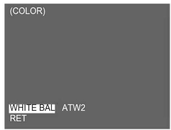
WHITE BAL
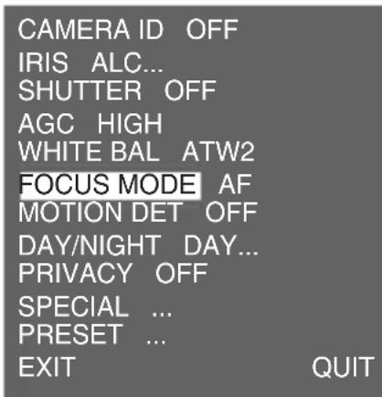
The [WHITE BAL] menu is used to configure the white balance related settings for this camera.
CAMERA ID OFF
IRIS ALC...
SHUTTER OFF
AGC HIGH
WHITE BAL ATW2
FOCUS MODE AF
MOTION DET OFF
DAY/NIGHT DAY...
PRIVACY OFF
SPECIAL ...
PRESET ...
EXIT QUIT
To adjust the white balance, 4 different modes are provided as follows:
-
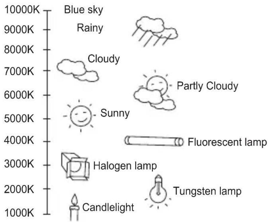
[ATW1] (Auto Tracing White Balance mode 1): The camera can automatically adjust the colour temperature in real time according to the ambient temperature change. The colour temperature variation range is approximately from 2500^ to 9300^ .
-
[ATW2]: Its colour temperature variation range is approximately from 2000^ to 10000^ .
-
[AWC←] (Auto White Balance Control): The colour temperature setting is made once. After selecting this, expose to an object to memorize the colour temperature of it and press the SETUP switch. The fixed colour temperature is applied.
-
[MANU...]: You can manually set the current colour temperature. You can also specify the settings for red and blue colours on your own.
Note
When the [DAY/NIGHT] is set to [NIGHT], [WHITE BAL] is displayed with “----”. You cannot adjust the settings manually. When it is set to [COLOR] in the [NIGHT] mode, the white balance will be setting as the same value in [COLOR] mode.
FOCUS MODE
In the [FOCUS MODE] menu, the focus method can be set to AF(Auto Focus), MF(Manual Focus), or ONEAF(One Auto Focus).
- [AF]: In the Auto Focus mode, you can monitor the screen continuously and it will focus automatically. If you manually adjust the focus, it operates as the same in Manual Focus mode. It automatically sets the focus after the zoom moves.
- [MF]: In the Manual Focus mode, you can adjust the focus manually.
- [ONEAF]: In the ONEAF mode, it automatically sets the focus after the zoom moves, and operates as the same in the Manual Focus mode if the zoom does not move.
Note
※ AF function may not be possible with types of objects listed below. For such objects, focus manually.
- High intensity objects or objects illuminated with low lighting
- Objects shot through wet or dirty glass
- Pictures that are a mixture of distant and nearby objects
- White walls and other single-colour objects
- Venetian blinds and other horizontally striped objects
MOTION DET
[MOTION DET] menu is used to configure the motion detection related settings. If you press the SETUP switch when [ON...] is selected in the [MOTION DET] menu, the corresponding screen appears.
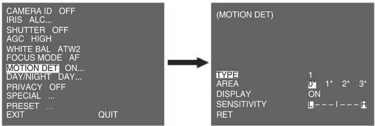
You cannot change the setting for type 2 because it is prefixed with the full screen. In case of 1 and 3, you can set the motion detection area on your own.
Those 3 types are like the following:
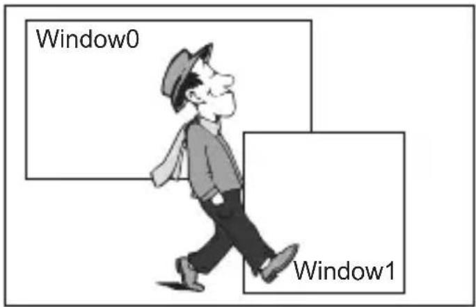
1. Window Type
The selected area is displayed with a box. The motion can be detected for the area only. You can manually set the motion detection area. You can use the Up/Down/Left/Right SETUP switch to set the size. To move to [POSITION], press the SETUP switch. After setting the position using the Up/Down/Left/Right SETUP switch, press the SETUP switch to move to the upper menu. To set the size and position for [AREA], select any of 0, 1, 2, and 3.
Note
The selected window for AREA is displayed in white and the unselected one is displayed in black.
2.Label Type
The box-typed motion detection area is prefixed. The detected area is displayed with size and position changing. You cannot change [AREA] because it is displayed with [---].
3. Block Type
The screen displays with small blocks. When a motion is detected in the selected blocks, the small blocks are displayed on the screen.
- [PRESET]: The whole screen becomes the motion detection area.
- [USER...]: You can manually set the motion detection area. Use the Up/Down/Left/Right SETUP switch to set the area. To erase the selected block, press the SETUP switch.

To select [RET], press UP key on the top block or press DOWN key on the bottom block and then press ENTER key to return a upper menu.
In order to set the motion detection area on your own, you have to specify the size and location for the area setting. When [ON] is selected in [DISPLAY], the detected motion is displayed on the screen and the camera sends the Alarm Out signal. You can also assign the sensitivity for motion detection.
Note
※ MOTION DET menu is not available for the first 5 seconds after operating the PAN/TILT/ZOOM/FOCUS/IRIS functions.
× Since the motion detecting function depends on the brightness of selected area, it may dysfunction due to the different brightness between the background and object.
DAY/NIGHT
The [DAY/NIGHT] menu is used to configure the day and night related settings for this camera. This camera can turn the IR (Infrared) filter on or off.
CAMERAID OFF
IRIS ALC...
SHUTTER OFF
AGC HIGH
WHITE BAL ATW2
FOCUS MODE AF
MOTION DET OFF
DAY/NIGHT DAY...
PRIVACY OFF
SPECIAL ...
PRESET ...
EXIT QUIT
DAY...
If you press the SETUP switch when the [DAY...] submenu is selected, the corresponding screen appears. You can set the values for [C-GAIN] when the DAY... submenu is selected. You can set the values for [AGC COLOR] and [AGC DETAIL] while the AGC menu is selected.
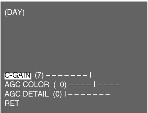
Note
When the value of [AGC DETAIL] becomes large, it also makes the noise stand out.
NIGHT...
If you press the SETUP switch when the [NIGHT...] submenu is selected, the corresponding screen appears.


Even in the Night mode, you can see colour images in bright illumination. Therefore, you can select any of [COLOR...] and [BW...]. In case of [COLOR...], you have to set the colour temperature for white balance. You can also specify the settings for red and blue colours on your own. In case of [BW...], the burst signals are output with the BW Composite Video signals, when the BURST is set to [ON]. And no burst signals are output when the BURST is set to [OFF].
Note
When it is set to [NIGHT], [WHITE BAL] of the video set will be displayed as “---”. You cannot adjust the settings manually. When it is set to [COLOR] in the NIGHT mode, the white balance will be setting as the same value in [COLOR] mode.
AUTO...
This automatically converts the Day mode to the Night mode and vice versa depending on illumination. In low illumination, it removes the IR filtering function to raise the sensitivity. Otherwise, it activates the IR filtering function to lower the sensitivity.
If you press the SETUP switch when the [AUTO...] submenu is selected, the corresponding screen appears.
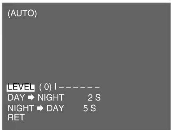
For this function, you can specify the level for each conversion between [DAY] and [NIGHT].
Note
When the [DAY/NIGHT] is set to [AUTO], the AGC is displayed with [---] so you cannot change its setting.
EXT
This automatically converts the colour mode to the BW mode and vice versa by interfacing with an external sensor.
| CAMERA ID OFF |
| IRIS ALC... |
| SHUTTER OFF |
| AGC HIGH |
| WHITE BAL ATW2 |
| FOCUS MODE AF |
| MOTION DET OFF |
| DAY/NIGHT EXT |
| PRIVACY OFF |
| SPECIAL ... |
| PRESENT ... |
| EXIT QUIT |
PRIVACY
The [PRIVACY] menu is used to configure the privacy related settings for this camera. If you press the SETUP switch when [ON...] is selected in the [PRIVACY] menu, the corresponding screen appears.
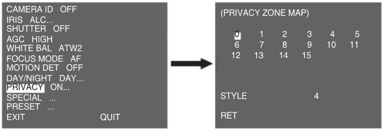

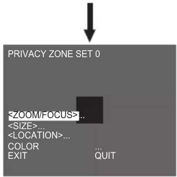
You can set 16 privacy zones in total. For configuration for 0 to 15 zones, you have to set the size, location, and colour.
Note
※ For the safer privacy protection, select about 10 % more than the actual area to hide when you set up the PRIVACY ZONE area.
The mosaic of the recorded images is set to be the PRIVACY ZONE. The mosaic of the recorded images can not be recovered after recording.
SPECIAL
The [SPECIAL] menu is used to configure the special settings for this camera. If you press the SETUP switch when [...] is selected in the [SPECIAL] menu, the corresponding screen appears.
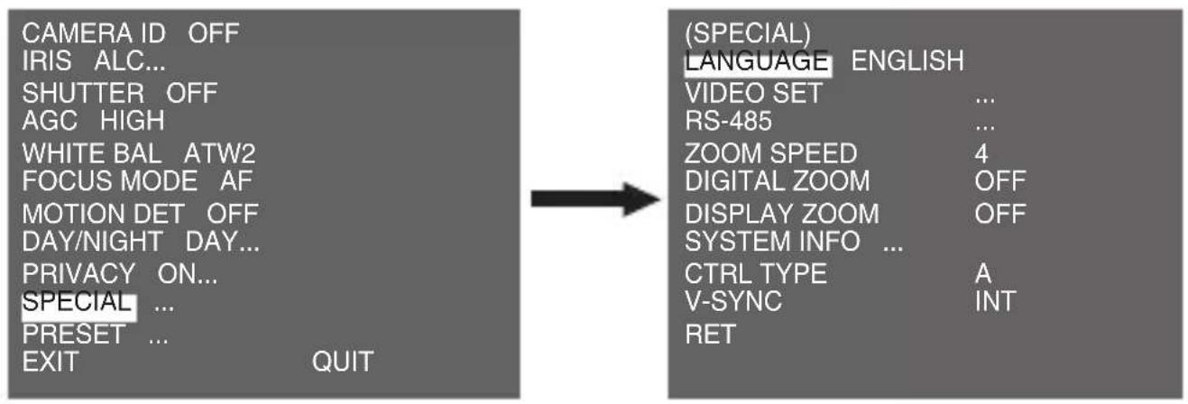
LANGUAGE
You can change the OSD language using the Left/Right SETUP switch.
Note
Selectable languages may vary depending on sales region.
VIDEO SET
The [VIDEO SET] menu is used to configure the privacy related settings for this camera. If you press the SETUP switch when [ON...] is selected in the [PRIVACY] menu, the corresponding screen appears.
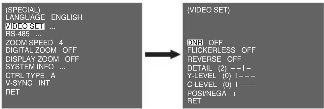
DNR
DNR(Digital Noise Reduction) function enables the picture to be reduced noise.
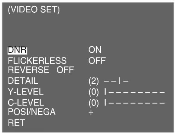
FLICKERLESS
When this is set to [ON], the shutter speed is set to 1/100 sec (for NTSC) or 1/120 sec (for PAL) to prevent from flickering by the discordance between vertical synchronization frequency and on-and-off frequency of the light.
REVERSE
It is used to mirror video signals horizontally, vertically, or both.
DETAIL
It is used to control the horizontal or vertical distinction.
Y-LEVEL
It is used to set the levels for the Sync signal and the entire brightness signal of the video signal.
C-LEVEL
It is used to set the levels for the Burst signal and the entire colour signal of the video signal.
POSINEGA
It is used to output as it is, or mirror the video brightness signal.
RS-485
If you press the SETUP switch when [...] is selected in the [RS-485] menu, the corresponding screen appears.
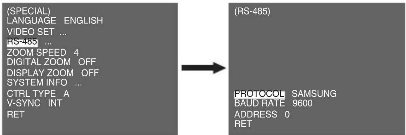
You can set the PROTOCOL, BAUD RATE, and ADDRESS (range: 0 to 255) for this communication.
ZOOM SPEED
(SPECIAL)
LANGUAGE ENGLISH
VIDEO SET ...
RS-485 ...
ZOOM SPEED 4
DIGITAL ZOOM OFF
DISPLAY ZOOM OFF
SYSTEM INFO ...
CTRL TYPE A
V-SYNC INT
RET
Use the Left/Right SETUP switch in the [ZOOM SPEED] menu to select the speed.
1:Slowest speed
2:Low speed
3:High speed
4:Fastest speed
DIGITAL ZOOM
You may set up the digital zoom magnification ratio in the [DIGITAL ZOOM] menu. The magnification ratio ranges from [OFF] to 16 times. If you set Digital Zoom of the camera to maximum 16 times, the mode will become the 32 time optical zoom and you will be able to enlarge a subject by maximum 512 times. Use the Left/Right SETUP switch to select a magnification ratio in the [DIGITAL ZOOM] menu.
(SPECIAL)
LANGUAGE ENGLISH
VIDEO SET ...
RS-485 ...
ZOOM SPEED 4
DIGITAL ZOOM X16
DISPLAY ZOOM OFF
SYSTEM INFO ...
CTRL TYPE A
V-SYNC INT
RET
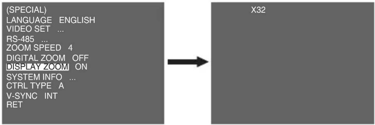
DISPLAY ZOOM
In the [DISPLAY ZOOM] menu, you can display the ZOOM scale on the screen.
Note
When the [DAY/NIGHT] is set to [AUTO], the AGC is displayed with [---] so you cannot change its setting.
SYSTEM INFO
This [SYSTEM INFO] menu is used to check the system-related information. If you press the SETUP switch when the [SYSTEM INFO] menu is selected, the corresponding setup screen appears.
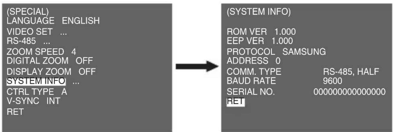
You can find the system information about ROM version, EEP version, protocol, address, type, baudrate, and serial number.
CTRL TYPE
By inputting the wire remote port, you may set up the A, B, C or D mode.
| Code | Tele | Wide | Far | Near |
| A -6V +6V +6V -6V | ||||
| B -6V +6V -6V +6V | ||||
| C +6V -6V +6V -6V | ||||
| D +6V -6V -6V +6V |
V-SYNC
You can select a vertical synchronization mode between [INT] and [LINE]. In case of [INT], the camera uses the inside crystal oscillator for synchronization. In case of [LINE], the camera uses the frequency of the external power for synchronization.
Note
- In case of [LINE], SCC-C4333(P)/SCC-C4335(P) doesn't support for DC 12V, which [- - -] is displayed.
- SCC-C4233(P)/C4235(P) does not support for V-SYNC function.
PRESET
Select the [PRESET] menu and press the SETUP switch and the [PRESET MAP] submenu screen will appear.
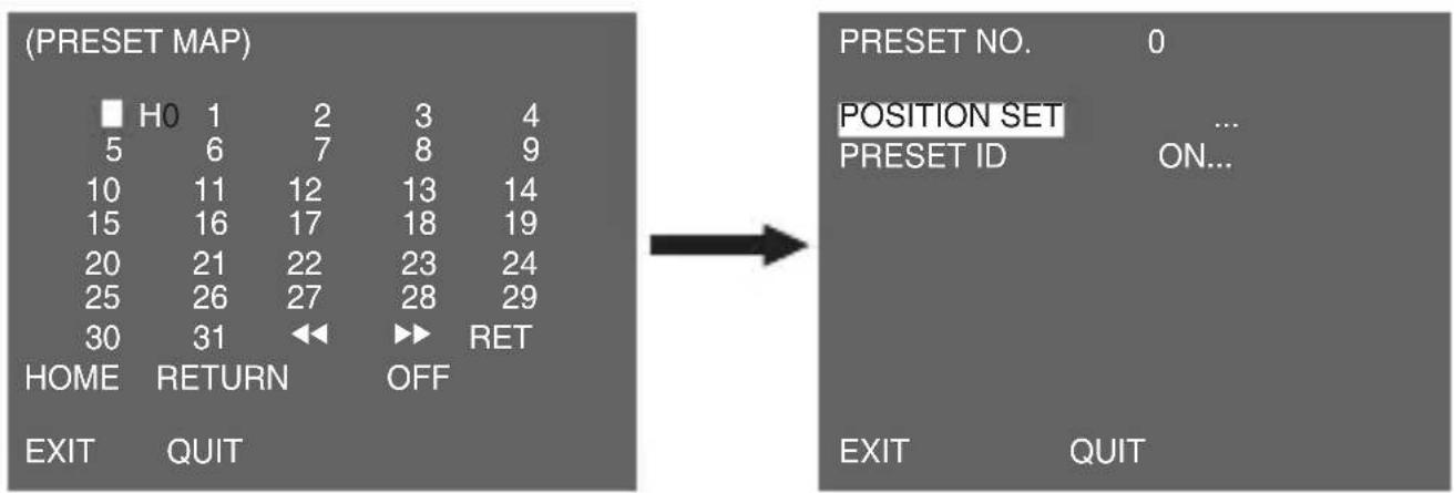
Select the PRESET number and press the SETUP switch and the above screen will appear.
POSITION SET
It is used to memorize the position of ZOOM or FOCUS.
PRESET ID
It is used to designate the ID on the basis of the PRESET position as the [CAMERA ID].
Note
[HOME RETURN] automatically returns to the HOME position if there is no key input for a certain time. The HOME position is set to PRESET 0 if it is saved, or [Off] if not.
HOME RETURN Time Setup OFF 1MIN 2MIN 3~60MIN 2 HOUR 3~12 HOUR
| ItemDetails | |||||
| Product type CCTV Camera | |||||
| Power source | SCC-C4233(P)/SCC-C4235(P) : DC 12V±10% SCC-C4333/C4335 : AC 24V ± 10% (60Hz ± 0.3Hz) SCC-C4333P/C4335P : AC 24V ± 10% (50Hz ± 0.3Hz) | ||||
| Broadcast type | SCC-C4233(5)/C4333(5) : NTSC Standard Colour System SCC-C4233(5)P/C4333(5)P : PAL Standard Colour System | ||||
| Power consumption | SCC-C4233(P) : 4W SCC-C4235(P) : 5W SCC-C4333(P) : 5W SCC-C4335(P) : 5.5W | ||||
| Image device | SCC-C4233(P)/C4333(P) : 1/4" Super-HAD IT CCD SCC-C4235(P)/C4335(P) : 1/4" ExView-HAD PS CCD | ||||
| Effective pixels SCC-C4233(5)/C4333(5) : 768(H) x 494(V) SCC-C4233(5)P/C4333(5)P : 752(H) x 582(V) | |||||
| Scanning line frequency | Horizontal: NTSC -15,734Hz(INT)/15,750Hz(LL) PAL -15,625Hz(INT)/15,625Hz(LL) Vertical: NTSC -59.94Hz(INT)/60Hz(LL) PAL -50Hz(INT)/50Hz(LL) | ||||
| Synchronization mode | INT/Line Lock (SCC-C4233(P)/C4235(P) does not support for Line Lock function.) | ||||
| Resolution 540(COLOR)/570(BW) TV Lines | |||||
| S/N Ratio Approx. 50dB | |||||
| ItemDetails | |||||
| Min. Scene Illumination | Condition | SCC-C4233(P)/C4333(P) | SCC-C4235(P)/C4335(P) | ||
| Illumination | Sens-upColourB/WColourB/W | ||||
| 50IRE Off 2.0 0.20 1.2 0.12 | |||||
| 30IRE Off 1.2 0.12 0.7 0.07 | |||||
| 15IRE Off 0.6 0.06 0.3 0.03 | |||||
| 50IRE x256 0.008 0.0008 0.005 0.0005 | |||||
| 30IRE x256 0.005 0.0005 0.003 0.0003 | |||||
| 15IRE x256 0.002 0.0002 0.001 0.0001 | |||||
| Wide Dynamic Range | SCC-C4233(P)/C4333(P) : N/ASCC-C4235/C4335 : x128SCC-C4235P/C4335P : x160 | ||||
| Electronic shutter speed | High Speed: OFF~1/10K secLow Speed: OFF~X256 | ||||
| DIGITAL ZOOM 2x ~ 16x | |||||
| White Balance ATW1/ATW2/AWC/MANUAL Mode(3200°K, 5600°K, R/B Gain adjustment) | |||||
| Signal output COMPOSITE VIDEO OUT : 1.0 Vp-p 75 ohms/BNC | |||||
| Operation temperature | -10°C~+50°C | ||||
| Operation humidity | ~90% | ||||
| Size NET(WxHxD) : SCC-C4233(5)(P) : 60.5x59.5x125.2SCC-C4333(5)(P) : 60.5x59.5x159.2 | |||||
| Weight NET : SCC-C4233(5)(P) : 444gSCC-C4333(5)(P) : 595gGROSS : SCC-C4233(5)(P) : 552gSCC-C4333(5)(P) : 717g | |||||

Correct Disposal of This Product
(Waste Electrical & Electronic Equipment)
(Applicable in the European Union and other European countries with separate collection systems)
This marking shown on the product or its literature, indicates that it should not be disposed with other household wastes at the end of its working life. To prevent possible harm to the environment or human health from uncontrolled waste disposal, please separate this from other types of wastes and recycle it responsibly to promote the sustainable reuse of material resources.
Household users should contact either the retailer where they purchased this product, or their local government office, for details of where and how they can take this item for environmentally safe recycling.
Business users should contact their supplier and check the terms and conditions of the purchase contract. This product should not be mixed with other commercial wastes for disposal.
SAMSUNG
SCC- C4233(P)/C4333(P)/
C4235(P)/C4335(P)
Bedienungsanleitung

SCC-C4233(P)/C4235(P) SCC-C4333(P)/C4335(P)
SCC- C4233(P)/C4333(P)/
C4235(P)/C4335(P)
Guide d'utilisation

SCC-C4233(P)/C4235(P) SCC-C4333(P)/C4335(P)
SCC- C4233(P)/C4333(P)/
C4235(P)/C4335(P)
Manual de usuario

SCC-C4233(P)/C4235(P) SCC-C4333(P)/C4335(P)
1 Conector de Entrada/Salida
SCC- C4233(P)/C4333(P)/
C4235(P)/C4335(P)
Manuale d'uso

SCC-C4233(P)/C4235(P) SCC-C4333(P)/C4335(P)
Tasto SETUP Tastio SETUPTasto SETUP
SCC- C4233(P)/C4333(P)/
C4235(P)/C4335(P)
Kullanı Kilavuzu

SCC-C4233(P)/C4235(P) SCC-C4333(P)/C4335(P)