SBE 561 - Drill METABO - Free user manual and instructions
Find the device manual for free SBE 561 METABO in PDF.

User questions about SBE 561 METABO
0 question about this device. Answer the ones you know or ask your own.
Ask a new question about this device
Download the instructions for your Drill in PDF format for free! Find your manual SBE 561 - METABO and take your electronic device back in hand. On this page are published all the documents necessary for the use of your device. SBE 561 by METABO.
USER MANUAL SBE 561 METABO
natural_image
Black-and-white photo of multiple metalworking machines with drill bits, no visible text or symbols on the main image.
text_image
GRIP, ZU b a b a AUF, RELEASE 3 x3


A
6.31078
B
6.27608
C
natural_image
Mechanical press or clamping device with lever and base mount (no visible text or symbols)6.00890
D
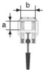
a=80
b=80
6.27106
a=100
b=100
6.12001
a=86
b=80
6.12003
E

6.30554
F

G

H

SBE 561, SBE 521
| ALU | ||||
| 4 | ||||
| 6 | ||||
| 8 | ||||
| 10 | ||||
| 12 | ||||
| 16 | ||||
| 20 |
| 1 | 2 | 3 | 4 | 5 | 6 | |
| SBE 521 | 1100 | 1400 | 1700 | 2000 | 2300 | 2600 .../min |
| SBE 561, BE 561 | 1300 | 1600 | 1900 | 2200 | 2500 | 2800 .../min |
| 50 | 40 | 30 | 20 15 10 % | |||
Operating Instructions
Dear Customer,
Thank you for the trust you have placed in us by buying a Metabo power tool. Each Metabo power tool is carefully tested and subject to strict quality controls by Metabo's quality assurance. Nevertheless, the service life of a power tool depends to a great extent on you. Please observe the information contained in these instructions and the enclosed documentation. The more carefully you treat your Metabo power tool, the longer it will provide dependable service.
Contents
1 Specified Conditions of Use
2 General Safety Instructions
3 Special Safety Instructions
4 Overview
5 Initial Operation
5.1 Attaching the Additional Handle (SBE 561, SBE 521, SB 561)
6 Use
6.1 Adjusting the Depth Stop (SBE 561, SBE 521, SB 561)
6.2 Switching On and Off
6.3 Speed Preselection (SBE 561, SBE 521, BE 561)
6.5 Selecting the Direction of Rotation (SBE 561, SBE 521, BE 561)
6.6 Tool Change With Futuro Plus Keyless Chuck (3)
6.7 Tool Change With Geared Chuck (2)
6.8 Removing the Chuck
7 Tips and Tricks
8 Maintenance
9 Accessories
10 Repairs
11 Environmental Protection
12 Technical Specifications
1 Specified Use
SBE 561, SBE 521, SB 561:
The machine is suitable for non-impact drilling in metal, wood, plastic and similar materials and impact drilling in concrete, stone and similar materials.
BE 561, B 561:
The machine is suitable for non-impact drilling in metal, wood, plastic and similar materials.
SBE 561, SBE 521, BE 561:
The machine is suitable for thread cutting and screwdriving.
The user bears sole responsibility for damage caused by improper use.
Generally accepted accident prevention regulations and the enclosed safety information must be observed.
2 General Safety Instructions

WARNING Read all safety warnings and all instructions. Failure to follow the warn-
ings and instructions may result in electric shock, fire and/or serious injury. Save all warnings and instructions for future reference! The term
"power tool" in the warnings refers to your mains-operated (corded) power tool or battery-operated (cordless) power tool.
1) Work area safety
a) Keep work area clean and well lit. Cluttered or dark areas invite accidents.
b) Do not operate power tools in explosive atmospheres, such as in the presence of flammable liquids, gases or dust. Power tools create sparks which may ignite the dust or fumes.
c) Keep children and bystanders away while operating a power tool. Distractions can cause you to lose control.
2) Electrical safety
a) Power tool plugs must match the outlet. Never modify the plug in any way. Do not use any adapter plugs with earthed (grounded) power tools. Unmodified plugs and matching outlets will reduce risk of electric shock
b) Avoid body contact with earthed or grounded surfaces, such as pipes, radiators, ranges and refrigerators. There is an increased risk of electric shock if your body is earthed or grounded.
c) Do not expose power tools to rain or wet conditions. Water entering a power tool will increase the risk of electric shock.
d) Do not abuse the cord. Never use the cord for carrying, pulling or unplugging the power tool. Keep cord away from heat, oil, sharp edges or moving parts. Damaged or entangled cords increase the risk of electric shock.
e) When operating a power tool outdoors, use an extension cord suitable for outdoor use. Use of a cord suitable for outdoor use reduces the risk of electric shock.


ENG ENGLISH
f) If operating a power tool in a damp location is unavoidable, use a residual current device (RCD) protected supply. Use of an RCD reduces the risk of electric shock.
3) Personal safety
a) Stay alert, watch what you are doing and use common sense when operating a power tool. Do not use a power tool while you are tired or under the influence of drugs, alcohol or medication. A moment of inattention while operating power tools may result in serious personal injury.
b) Use personal protective equipment. Always wear eye protection. Protective equipment such as dust mask, non-skid safety shoes, hard hat, or hearing protection used for appropriate conditions will reduce personal injuries.
c) Prevent unintentional starting. Ensure the switch is in the off-position before connecting to power source and/or battery pack, picking up or carrying the tool. Carrying power tools with your finger on the switch or energising power tools that have the switch on invites accidents.
d) Remove any adjusting key or wrench before turning the power tool on. A wrench or a key left attached to a rotating part of the power tool may result in personal injury.
e) Do not overreach. Keep proper footing and balance at all times. This enables better control of the power tool in unexpected situations.
f) Dress properly. Do not wear loose clothing or jewellery. Keep your hair, clothing and gloves away from moving parts. Loose clothes, jewellery or long hair can be caught in moving parts.
g) If devices are provided for the connection of dust extraction and collection facilities, ensure these are connected and properly used. Use of dust collection can reduce dust-related hazards.
4) Power tool use and care
a) Do not force the power tool. Use the correct power tool for your application. The correct power tool will do the job better and safer at the rate for which it was designed.
b) Do not use the power tool if the switch does not turn it on and off. Any power tool that cannot be controlled with the switch is dangerous and must be repaired.
c) Disconnect the plug from the power source and/or the battery pack from the power tool before making any adjustments, changing accessories, or storing power tools. Such preventive safety measures reduce the risk of starting the power tool accidentally.
d) Store idle power tools out of the reach of children and do not allow persons unfamiliar with the power tool or these instructions to
operate the power tool. Power tools are dangerous in the hands of untrained users.
e) Maintain power tools. Check for misalignment or binding of moving parts, breakage of parts and any other condition that may affect the power tool's operation. If damaged, have the power tool repaired before use. Many accidents are caused by poorly maintained power tools.
f) Keep cutting tools sharp and clean. Properly maintained cutting tools with sharp cutting edges are less likely to bind and are easier to control.
9) Use the power tool, accessories and tool bits etc. in accordance with these instructions, taking into account the working conditions and the work to be performed. Use of the power tool for operations different from those intended could result in a hazardous situation.
5) Service
a) Have your power tool serviced by a qualified repair person using only identical replacement parts. This will ensure that the safety of the power tool is maintained.
3 Special Safety Instructions
Wear ear protectors with impact drills.
Exposure to noise can cause hearing loss.
Use auxiliary handles supplied with the tool.
Loss of control can cause personal injury.
Hold power tool by insulated gripping surfaces when performing an operation where the cutting tool may contact hidden wiring or its own cord. Contact with a "live" wire will also make exposed metal parts of the power tool "live" and shock the operator.

For your own protection and the protection of your power tool, observe the passages marked by this symbol!
Keep all enclosed documentation for future reference, and pass on your power tool only together with this documentation.
Pull the plug out of the plug socket before any adjustments or servicing are performed.
Beware of gas/water pipes and electric cables!
Avoid inadvertent starts by always unlocking the switch when the plug is removed from the mains socket or in case of a power cut.
Keep hands away from the rotating tool!
Remove chips and similar material only with the machine at standstill.
Caution must be exercised when driving screws into hard materials (driving screws with metric or


ENGLISH
ENG
imperial threads into steel)! The screw head may break or a high reverse torque may build up.
The machine produces powerful forces when seizing or catching the workpiece. Always hold the machine firmly, adopt a steady stance and focus on your work.
Secure small workpieces. For example, clamp in a vice.
SYMBOLS ON THE TOOL:

......Class II Construction
V.....volts
A.....amperes
Hz......hertz
BPM.....beat per minute
\~ ......alternating current
4 Overview
See page 3 (please unfold).
1 Chuck key (for geared chuck) *
2 Geared chuck *
3 Futuro Plus keyless chuck *
4 Depth stop *
5 Additional handle *
6 Direction switch *
7 Sliding switch for normal drilling/impact drilling *
8 Lock button (continuous operation)
9 Trigger
10 Speed preselection wheel *
* depending on the features / model
5 Commissioning

Before plugging in, check to see that the rated mains voltage and mains frequency, rated on the rating label, match with your user supply.

SBE 561, SBE 521, BE 561: Make sure the chuck clamps securely:
After drilling for the first time (clockwise), firmly tighten the safety screw inside the chuck using a screwdriver. Caution: left-handed thread! (see Section 6.8)
5.1 Attaching the Additional Handle
(SBE 561, SBE 521, SB 561)

For safety reasons, always use the additional handle supplied.
Open the clamping ring by turning the additional handle (5) anticlockwise. Push the additional handle onto the collar of the machine. Insert the
depth stop (4). Securely tighten the additional handle at the angle required for the application.
6 Use
6.1 Adjusting the Depth Stop
(SBE 561, SBE 521, SB 561)
Loosen the additional handle (5). Set depth stop (4) to the desired drilling depth and retighten additional handle.
6.2 Switching On and Off
To start the machine, press the trigger switch (9). SBE 561, SBE 521, BE 561: Press in the trigger switch to change the speed.
For continuous operation the trigger switch can be locked using the lock button (8). To stop the machine, press the trigger switch again.

In continuous operation, the machine continues running if it is forced out of your ls. Therefore, always hold the machine both hands using the handles provided, and in a safe position and concentrate.
6.3 Speed Preselection
(SBE 561, SBE 521, BE 561)
Select the (10) maximum speed using the preselection wheel. See page 4 for recommended drilling speeds.
6.4 Switching Between Normal Drilling/Impact Drilling
(SBE 561, SBE 521, SB 561)
Select the desired operating mode by pushing the sliding switch (7).

Drilling

Impact drilling
Work with high speed settings when impact drilling.

Impact drilling and normal drilling only in a clockwise direction.
6.5 Selecting the Direction of Rotation
(SBE 561, SBE 521, BE 561)

Do not activate the direction switch (6) unless the motor has completely stopped.


ENGLISH
Select direction of rotation:
$$ R = C l o c k w i s e $$
$$ L = \text { A n t i c l o c k w i s e } $$

Screw the chuck firmly to the spindle and tighten the safety screw inside the chuck g a screwdriver. (Caution: left-handed ad!)
Otherwise it may come loose during anticlockwise operation (e.g. when screwdriving).
6.6 Tool Change With
Futuro Plus Keyless Chuck (3)
Machines with the designation SB...:
See illustrations on page 3.
Insert the tool. Hold the retaining ring (a) firmly and turn the collet (b) towards "GRIP, ZU" with the other hand until the mechanical resistance which can be felt is overcome.
Caution! The tool is not yet clamped! Keep turning the sleeve (it must "click" when turning) until it cannot be turned any further - only now is the tool securely clamped.
With a soft tool shank, retightening may be required after a short drilling period.
Open the chuck:
Hold the retaining ring (a) firmly and turn the collet (b) towards "AUF, RELEASE" with the other hand.
Note: The grating sound which may be heard after opening the drill chuck is functional and is stopped by turning the sleeve in the opposite direction.
If the chuck is very securely tightened: Unplug. Hold the drill chuck using an open-end spanner at the flats on its head, and turn the sleeve (b) vigourously in the direction of "AUF, RELEASE".
Machines with the designation B...:
See illustrations on page 3.
Insert the tool. Hold the retaining ring (a) firmly and turn the collet (b) towards "GRIP, ZU" with the other hand until it will not turn any further.
With a soft tool shank, retightening may be required after a short drilling period.
Open the chuck:
Hold the retaining ring (a) firmly and turn the collet (b) towards "AUF, RELEASE" with the other hand.
If the chuck is very securely tightened: Unplug. Hold the drill chuck using an open-end spanner at the flats on its head, and turn the sleeve (b) vigourously in the direction of "AUF, RELEASE".
6.7 Tool Change With
Geared Chuck (2)
See illustrations on page 3.
Clamping tools:
Insert the tool and clamp evenly in all 3 holes using the chuck key (1).
Removing tools:
Open the geared chuck (2) using the chuck key (1) and remove the tool.
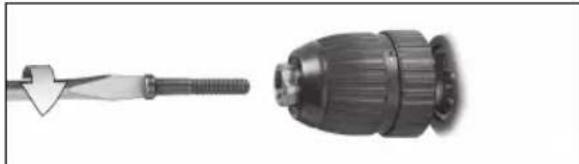
6.8 Removing the Chuck
Futuro Plus keyless chuck
natural_image
Two mechanical components: a tool with a triangular tip and a cylindrical drill bit (no text or symbols visible)Unscrew the safety screw - if available. Caution: left-handed thread!
natural_image
Close-up of a hand holding a drill bit with a tool, no visible text or symbolsHold the drill spindle securely using an open-end wrench. Clamp an Allen key in the chuck and strike lightly with a rubber hammer to loosen, then unscrew.
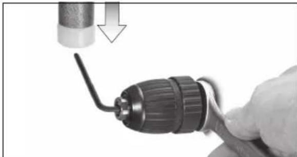
Geared chuck
natural_image
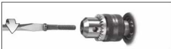
Mechanical component diagram showing a threaded shaft and a mechanical gear assembly (no text or symbols)Unscrew the safety screw - if available. Caution: left-handed thread!
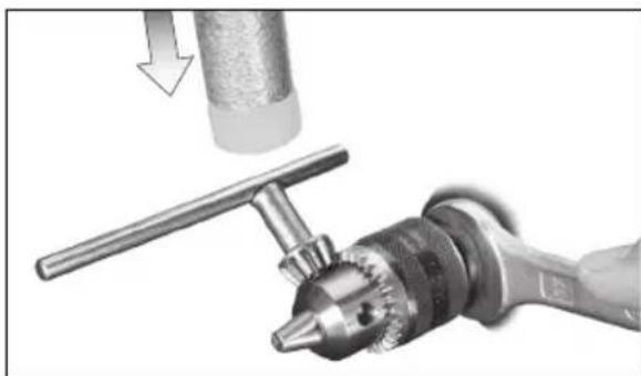
natural_image
Close-up of a mechanical tool with a drill bit and a cylindrical component, showing a downward arrow indicating motion (no text or symbols present)Hold the drill spindle securely using an open-end wrench. Insert the key in the chuck and strike


ENGLISH
ENG
lightly with a rubber hammer to loosen, then unscrew.
7 Tips and Tricks
In the case of deep bores, pull the drill bit out of the bore from time to time in order to remove the drill dust or swarf.
SBE 561, SBE 521, BE 561: The chuck can be removed to insert a screwdriver bit. Insert the bit directly in the hexagon socket on the spindle. The screwdriver bit is retained if a bit clamping bush (as an accessory: order no. 6.31281) is fitted.
8 Maintenance
Keyless chuck cleaning:
After prolonged use hold the chuck vertically, with the opening facing down, and fully open and close it several times. The dust collected falls from the opening. Regular use of cleaning spray on the jaws and jaw openings is recommended.
9 Accessories
Use only genuine Metabo accessories.
If you need any accessories, check with your dealer.
For dealers to select the correct accessory, they need to know the exact model designation of your power tool.
See page 4.
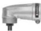
A Angle attachment
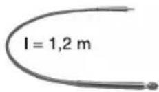
B Flexible drive shaft
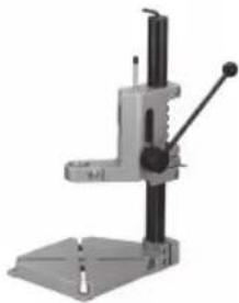
C Drill stand
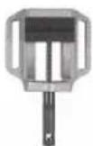
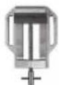
D Machine vice
E Steel wire end brush
F Steel wire cup brush
G Steel wire wheel
H Bit clamping bush
For complete range of accessories, see www.metabo.com or the main catalogue.
10 Repairs
Repairs to electrical tools must be carried out by qualified electricians ONLY!
Any Metabo power tool in need of repair can be sent to one of the addresses listed in the spare parts list.
Please enclose a description of the fault with the power tool.
11 Environmental Protection
Metabo's packaging can be 100% recycled.
Scrap power tools and accessories contain large amounts of valuable resources and plastics that can be recycled.
These instructions are printed on chlorine-free bleached paper.
12 Technical Specifications
Explanatory notes on the specifications on page 2. Changes due to technological progress reserved.
P_1 = Nominal power input
P2 = Power output
n_0 = No load speed
n_1 = Speed at rated load
ø max = Max. solid drill diameter
s max = Max. impact rate
G = Drill spindle thread
H = Drill spindle with hexagon socket
m = Weight without mains cable
D = Collar diameter
During operation the noise level can exceed 85 dB(A).

Wear ear protectors!
The technical specifications quoted are subject to tolerances (in compliance with the relevant valid standards).


F
FRANÇAIS
Mode d'emploi
Cher client,
Perçage sans percussion