MonoPoly - Synthesizer BEHRINGER - Free user manual and instructions
Find the device manual for free MonoPoly BEHRINGER in PDF.
User questions about MonoPoly BEHRINGER
0 question about this device. Answer the ones you know or ask your own.
Ask a new question about this device
Download the instructions for your Synthesizer in PDF format for free! Find your manual MonoPoly - BEHRINGER and take your electronic device back in hand. On this page are published all the documents necessary for the use of your device. MonoPoly by BEHRINGER.
USER MANUAL MonoPoly BEHRINGER
Analog 4-Voice Polyphonic Synthesizer with 37 Full-Size Keys, 4 VCOs, VCF, 2 LFOs, 2 Envelopes, Sync and Cross Modulation and Arpeggiator
Terminals marked with this symbol carry electrical current of sufficient magnitude to constitute risk of electric shock. The term is used when lacking plugs are pre installed. All other installation or modification should be performed only by qualified personnel.
This symbol, wherever it appears, shorts you to the presence of unbalanced dangerous voltage inside the enclosure - voltage that may be sufficient to constitute a risk of shock.
This symbol, wherever it appears, stries you to important operating and maintenance instructions in the accompanying literature. Please read the manual.
Caution To reduce the risk of electric shock, do not remove the impurity (or the iron section). No user serviceable parts include. Refer to following to qualified personnel.
Caution To reduce the risk of fire or electric sheeps, do not expose this apparatus to radiant and moisture. The apparatus shall not be exposed to drying or splashing inks and no objects filled with needles, such as warts, shall be placed on the apparatus.
Caution These service instructions are foruse by qualified service personnel only. To reduce the risk of electric shock do not perform any servicing other than that contained in the operation instructions. Repairs have to be performed by qualified service personnel.
-
Read these instructions.
-
Keep these instructions.
-
Hed al warnings
-
Follow-almentchines
-
Do not use this apparatus near water. 6. Clean wells with germin
-
Do not mix any ventilation openings. Incllual in accordance with the manufacturer's instructions.
-
Do not treat any new or new sources such as the same species of a species (such as 'inclamming amplifier' that produces heat).
-
Do not defeat the safety purpose of the polarized or grounding-type plug. A polarized plug has two blades with one water than the other. A grounding-type plug has two blades and a third grounding plug. The wide blade or the thin plug are provided for your safety. If the provided plug does not connect to your outlet, consult an electronic repair or replacement of the oblique outlet.
-
Protect the power cost from being walked on or pushed particularly at plugs, conveyance receptacles, and the points where they exit from the apparatus.
-
Use any attachment/accessories specified by the manufacturer.

- The only with the cart stand, tripod, bracket, or table specified by the manufacturer, or sold with the apparatus. When a cart is used, use caution when moving the cart/apparatus combination to avoid
Injury from tip-over.
- Unping the apparatus during lightning storms or when unpaired for long periods of time.
-
Refer all servicing to qualified service personnel. Servicing is required when the apparatus has been damaged in any way, such as power supply coil or plug is damaged, liquid has been spilled or objects have fallen into the apparatus, the apparatus has been exposed to rain or moisture, does not operate normally, or has been dropped.
-
The apparatus shall be cremented to a KAWKS socket outlet with a protective sealing connection.
-
Where the MINIS plug or an appliance coupler is used as the disconnect device, the disconnect device shall remain mostly unpatched.

- Correct disposal of this product: this symbol indicates that this product must not be disposed at with household waste, according to the USEPA Directive 2018-B/8 and your national law. This product
should be taken to a collection center (fremed) for the recycling of waste electrical and electronic equipment (IEE). The misdramizing of this type of waste could have a possible negative impact on the environment and human health due to potentially hazardous substances that are generally associated with EIE, at the same time, your cooperation in the correct disposal of this product will contribute to the efficient use of natural resources. For more information about where you can take your waste equipment for recycling, please contact your local city office, or your household waste collection service. 18. Do not install a confined space, such as a book case or similar unit. 19. Do not place placed flame sources, such as lighted cables, on the apparatus.
-
Please keep the environmental aspects of battery disposal in line. Batteries must be disposed of at a battery collection point.
-
This separation may be used in tropical and moderate climates up to 45^ .
LEGAL DISCLAIMER
Music: Tribe accepts on liability for any injury which may be suffered by any person who relies either wholly or in part upon any description, photograph, or statement contained herein. Technical specifications, appearances and other information are subject to change without notice. All trademarks are the property of their respective owners. Mids, Kink Teink, Lab Groupe, Laie, Tanov, Turbosound, TC Electronic, TC Helkon, Brehinger, Eureka, Acoustico and Cusado are trademarks or registered trademarks of Music, India Global brands Ltd., O Music: Tribe Global brands Ltd. 2010 All rights reserved.
LIMITED WARRANTY
For the applicable warranty term and conditions, and additional information regarding Mask Title's Limited Warranty, please see complete details online at www.madre.com/Warranty.
Instrucciones de
seguridad
CAUTION
R SK OF ELECTRIC SHOCK DO NOT OPEN
ATTENTION
RQUEDELECTRICUO
-
A corneata aniana a sua forma de comente electrlica asesquece de cuea constanza disponda a una union a thema.
-
Six minute cromosome of the next chromosome maps in mode of description, does there be an accurate factoring?

-
Leesrins
-
Guarantees inscructions
-
Preste intang a bados or avioe.
-
Siga codes as instroques
S. 40 of the elee disposio pento de aqua.
-
Limpelagen com um pann 500
-
如图所示,以线圈 l 为中性点,导体 l 与板边 a 连接,求导数 I_a
-
No italike pieto de quasique fonte caletari rathandratos, santo de o rirane, foghe de saia ou nutro aparenso [Indicando amplificaciones] que produz calor.
-
Nulo amelie o obsoleto de sequenza das difices politarizare con lo tipo di legistica a terra. Uma fichia politarici è dipara de duas pellettas semin cui non ha segno che alla sua. Uma fichia di tipolo e lata da se
de lae plaiti, et un tresere deante de liquie a terra, a palutha larga ou s'exercice dero cien formocides para sua sequencer. Se n'a fide formocides non coarizan na la tormata, ovoira um electrocdo para a subferencia da tubulacce abdale.
[1] KEYBOARD-the keyboard has 37 semi-weighted, full size keys.
MG1 WHEEL: adjust the modulation depth from off to maximum. The operation of both wheels can be adjusted and customized using the WHEEL controls [7].
BEND WHEEL - ratio or lower the pitch, with a center defint position.
KEY ASSIGN MODE these switches select how the keyboard is assigned to the synthesizer. (See "Getting Started" for more details. HOLD holds all notes played. Select a KEY ASSIGN switch, before pressing HOLD.)
[5] EFFECTS ON/OFF - enable/disable the effects produced using the X-KMOD/FREQ-KMOD/RCODE controls (see Item 11 below).
(4) ARPEGGATOR - three switches are used to set up the arpeggator.
CHORD MEMORY: play and hold any desired chord in POLY or UNISON/SHARE mode, and then press CHORD MEMORY. The chord will be memorized and can be played back with a single key press.
UNION: this monophasic mode plays all the VCOs when playing one key. Each VCO can be adjusted individually.
UNION/SHARE - this polyhmonic mode automatically shares the number of notes played, among the VCOs.
POLY - this conventional polyhmonic mode assigns the notes in the playing order to each VCO.
ALL/20CT/10CT selects the octave range.
UP/DOWN/UP-DOWN - selects the playback note order.
LATC/ON/OFF - Select LATC to hold the asparagus when all notes are released. Select ON or OFF to engage/disengage the asparagus. Use the M2G FREQUENCY knob to adjust the asparagus tempo. Make sure it is not on zero when first creating an asparagus.
WHEEL - this section allows you to select the operation and adjust the intensity of the BEND and WG1 wheels. INTENSITY - adjusts the intensity or effect of each wheel. On zero, the wheels will have no effect.
SELECTOR - select the operation of each wheel:
VCO1/SLAVEVCOs: the BIDM wheel affects VCO1 if the EFFC switch is OFF. If EFFC switches are On, then it affects the slave VCOs. The VCo1 wheel can modulate VCO1 or the slave VCOs.
Pitch - The SBIW wheel can pitch bend all WCG. The MG1 wheel can modulate the pitch.
VCF the BEND wheel directly affects the filter cutoff frequency, and the MST wheel modulates it.
OUTPUT- adjust the overall volume level of the main and headphone outputs. Turn this down before turning on power, or connecting headphones or external amplifiers and equipment.
FREQUENCY MG1 adjust the frequency of Modulation Generator 1 (MG1). The LED will flash at the current frequency,
WAVEFORM M61 - select the wave shape of (A61) form: triangular, reverse sawtooth, swatthout, or pulse
FREQUENCY M62 - adjust the frequency of Modulator Generator 2 (M62). The LID will flash at the current frequency. The M62 waveform is triangular.
X MOD/FREQ/MOD/MODE-use these controls to setup the effects, and then use the EFFECTS switch to turn these on or off. The various effects are based upon the relationship between a master VCO, and slave VCOs.
X-MOD - adjusts the level of cross-mutation when in X-MOD or S & X mode.
FREQ MOD - the knob and switch control the frequency modulation given to the slave VCOs only, as set by the SINGLE/DOUBLE switch.
MOD MODES
SYNC-the slave VCOs are synchronised in tune with their respective master VCO.
S & K-a combination of synchronised oscillators (S) and cross modulation (X).
X MOD - cross-modulation, where VCOs are frequency-modulated by another VCO. SINGLE - VCO1 is the master and VCO2-0 are all Saxes
DOUBLE: ^1CO1 is a master and WCO2 is slave. WCO is master and WCO4 is slave.
[13] PWLM-if you select PWLM as a waveform for the VCOs, use these controls to make adjustments:
VCO EG/MGI/MG2 - selects the source used to mediate the pulse width.
INTENSITY adjuststhe modulation intensity
[1] PWWIDTH - if you select PW as a waveform for the VCOs, use this control to adjust the pulse width from narrow to wide.
TRANSPOSE - this switch takes on lowers the keyboard by one octave, without having to adjust any KCO settings. It also affects the rear panel CV OUT, and the VCF 5188 TRACK control.
UP - raises the keyboard by one octave.
NORMAL this is the normal octave position.
DOWN - lowers the keyboard by one octave.
PORTAMENTO - adjust the amount of Portamento (or Glide), between notes as they are played.
[38] DETUME - adjust this control in Union mode to detune the 4 VOs in opposite directions to produce a latter sound. Reset to zero to return all the VOs for polyphonic playing.
MASTER TUNE - adjust the frequency of all VCOs 1 to 4.
[1] VCO 1,2,3,4-the MOVOLY has four voltage controlled oscillators (VCO), with similar controls. An LED indicates when each VCO is on.
TUNE- adjust the frequency of VCO 2, 3, or 4.
WAVEFORMA - select the wave shape from triangular, reverse saccitooth, PwM, or PV.
OCTAVE- select the VCD octave from 2', 4', 8, and 15.
LEVEL - adjust the output level of each VCO.
[19] VCF-the voltage controlled filter (VCF) is a low-pass filter, where audio frequencies above the cutoff frequency are attenuated.
CUTOFF adjusts the cutoff frequency.
RESONANCE - adjusts the amount of volume
level boost given at the out of frequency.
EG INTENSITY - adjusts how much the Filter Approach affects the QCF.
KYB TRACK adjusts how much the cutoff frequency follows (tracks); the keyboard. (For example, if you play higher notes, does the cutoff frequency also increase, or stay fixed.)
MONOPOLY Controls
(39) VCF EG- these knots adjust the envelope generator (EG): affecting the voltage controlled filter (VCF). The controls affect the change in cutoff frequency with time. ATTACK- adjust the time for the cutoff frequency to reach the frequency set by the CUTOFF control.
DECAY TIME - adjust the time for the cutoff frequency to decay down to the SLSIMF frequency after the attack time is over.
SUSTAIN - adjust the cutoff to a frequency which is sustained after the attack time and initial decay time have been reached.
RELEASE - adjust the time taken for the cutoff frequency to release after the note is released.
EVA CVA E6 - these knobs adjust the envelope generator (EG) affecting the voltage-controlled amplifier (VCA). The controls affect the change in volume with time.
ATTACK- adjust the time for the amplitude to reach its maximum level.
DECAY TIME - adjust the time for the amplitude to decay down to the SUSTAIN level after the attack time is over.
SUSTAIN - adjust the amplitude to a level which is sustained after the attack time and initial decay time have been reached.
RELEASE - adjust the time taken for the amplitude level to decrease after the note is released.
POWER - turn the synthesizer on off. Make sure all the connections are made before turning on the unit. The LED shows when power is applied and the synthesizer is turned on.
[35] AUTO DAMP ON/OFF - when the Off, and a chord is played in PCY mode, the chord will continue to play until all notes are released, or a new note is played. When ON, only non-released notes will continue to play; the others are damped.
[24] TRIGGER - There are two options for how the attack cycle of both envelope generators are triggered by the keyboard. [This also affects the near panel TRIG OUT].
SINGLE - a new note will trigger the attack cycle, but not if previous notes are being held, or held on.
MULTIPLE - a new note will trigger the attack cycle, even if previous notes are being held, or HOLD is on.
C91 NOISE - adjust the level of the Internal Noise source.
DC INPUT - connect the supplied 12V DC power adapter here. The power adapter can be plugged into an AC outlet capable of supplying from 100V to 240V at 50Hz / 60Hz . Use only the power adapter for the power adapter.
USB PORT: This USB type B Jack allows connection to a computer. The MONOPOLY evil show up as a class complaint USB MIDI device, capable of supporting MIDI in and out. USB MIDI1N- accepts incoming MIDI data from an application.
USB MIDI OUT - trends MIDI data to an application.
MIDIN: This 5 pin DVB jack receives MIDI data from an external source. This will commonly be an external MIDI keyboard, hardware sequencer, or a computer equipped with a MIDI interface.
MIDI OUT - this 5-pin DOK jack outputs
MIDI data
MIDI THRU this 5 pin D'ON jack is used to pass through MIDl data received at the MID INPU1.
(S) ARPEGGO - use this 1^st TRS deck input to trigger the ArPEGGO using an external device.
(60) PORTAMENTO - use this to engage or disengage the portamento using a footswitch.
VCF the filter's cutoff frequency can be modulated using a pedal, such as the Bohringer FC100 V2 or FC500 V2 expression pedal with the CV polarity set to TRS, and using a TRS cond:
230 VCO-the pitch can also be controlled using an pedal, such as those mentioned above.
TRIG POLARITY: selects the triggering polarity of ITOG in and out, from either +15V [positive-going, Voltage triggering] or ground [negative-going, Switch triggering].
TRIG - connect to the trigger inputs and outputs of another MODIPOV unit, compatible monophoric synthetases, or other modular equipment. Set the TRIG POLARITY switch to match the trigger inputs and outputs of your external equipment.
TRIG OUT connect this output to the trigger input of your external equipment. The output type is set by the TRIG POLARITY switch and follows the SINGLE/MULTIPLE TRIGGER front panel switch.
TRIG IN - connect this input to the trigger output of your external equipment. A trigger signal will turn all VCOs on and trigger the VCF and VCA Envelope Generator.
SVB - correct to the CI inputs and outputs of another MONOPOLY unit, compatible monophoric synthesizer, or other modular equipment. These should use the (TV/switch) control voltage system.
CV IN - connect this input to the CV output of your external equipment. Only the external voltages applied to this input will control the note. The VCOs will be in mono unison mode.
CVOUT - connect this output to the CV input of your external equipment. The output is of the highest rate, last played. The front panel TRANSPOSE switch will affect the CVOUT value by 1 volt changes per octave.
PHONES- connect your headphones to this "3s" TRS output. Make sure the headphones volume is turned down before putting on headphones.
OUTPUT- connect this ^ "s output to the line-level input of your external equipment.
Paso 2: Controles
SYNC-OS VPCs drive the synchronized ram, see respective VCO master.
PWWIDTH - as you choose PW currently, form a distance of 100 VCOs, use this centre for adjusting an amplitude of pulses of直径 to a ample.
TRANPOSE esbottoaumentoouabina o terchioe enuma otta,semse necessario aajuste de nenhumas designarconquadosde VCO. Elte meleftea o CV DUT op动画 traseiro s controlireyKTRKtadoVCO
MONOPOLY Getting started
OVERVIEW
This 'getting started' guide will help you set up the MOKOPOLY analog synthesizer and briefly introduce its capabilities.
CONNECTION
To connect the MONOPOLY to your system, please consult the connection guide earlier in this document.
SOFTWARE SETUP
The MONOPOLY V is a USB Class Compliant MBD device, and so no driver installation is required. The MONOPOLY does not require any additional drivers to work with Windows and Mac OS.
The "Synthetin" application allows you to select the MEDI channel number and to set and adjust various parameters of the MONIPOLY to suit your preferences. SysEx commands can also be used. Please see the information below in this manual.
HARDWARE SETUP
Make all the connections in your system. Apply coupler to the MOKIPOPLY using the supplied power adjuster only. Insure your sound system is turned off. Turn on the MOKIPOPLY Power switch
WARM UP TIME
We recommend loaning 15 minutes or more time for the MODOPOLY to warm up before recording online performance. [Longer if it has been brought in from the cold.] This will allow the precision analog circuit time to reach their normal operating temperature and tuned performance.
FIRST SOUNDS
The following steps will help you start making sounds from your new synthesizer:
1. Turn up the V01, U02, M4 small amount, and make sure the adjacent switch is set to high or low (not ON).
2. Tum the VCF CUTOFF to maximum.
3. Turn the VCA G5 SUSTAIN to 5 or more, and ATTACK to 0.
4. Tum the VCO1 LEVEL to maximum, and its WAVFOGRAM to triangular.
5. For the wheels to work, set their INTENSITY knob to 5 or more. Initially, set the MG1 wheel to minimum.
6. Play the keyboard and adjust the volume to a safe and comfortable level.
-
Adjust the LVEL and WAVEFORM of the other VCOs and experiment with the settings and tuning.
-
THE NOISE LEVEL can also be adjusted to add white noise.
VCO SECTION
The MOBOPOLY has four voltage controlled oscillators (VCO), and an internal Noise generator. Each of these, and any combination, are used to generate sound.
The VCO controls allows you to adjust the volume of each VCO, select its waveform, its octave, and its tuning. The MASTIR TUNE adjusts all VCOs at the same time. DETUNE will slightly separate the tuning of each VCO to create a faster sound similar to an ensemble. TRANPOSE will move all VCOs up or down an octave.
If you select PWM and PW waveforms, then you can adjust the modulation of the PWM, and the width of the PW.
VCF FILTER AND EG SECTION
The voltage controlled filter (VCF) is a low pass filter, where audio frequencies above the cutoff frequency are attenuated. Adjust the Cutoff Frequency, Resonance, and Intensity, and listen to their effects on the sound.
In the VCT EG envelope generator, adjust the Attack Time, Decay Time, Sustain Level and Release time; they affect the cutoff frequency with time, when a note is played. The VCT EG can also affect the modulation of the PINW waveform, and the frequency modulation in the Effects section.
The keyboard tracking knob affects how much the filter is affected by the frequency of notes that are played.
VCAEGSECTION
Adjust the voltage controlled amplifier envelope generator controls: Attack time, Decay time, Sustain level, and Release time. These affect the overall level with time, when a note is played.
MG1 and MG2
These are two separate modulation generators, and each can modulate different parameters for very interesting effects.
M61 has a frequency control, and the waveform can be selected from triangle, reverse-sawtooth, sawtooth, and pulse. M61 can be used to modulate the width of the PWM waveform, and the frequency modulation in the effects section. The M61 wheel adjusts the intensity, and it can mediate VCO1 (or state VCO) of EFCETS is on), the pitch, or the VCF cutoff frequency.
MG2 has a frequency control, and a triangular waveform. The frequency control can be used to adjust the Arpeggio tempo (make sure it is not on zero when using Arpeggio). MG2 can also modulate the width of the PWM waveform.
KEY ASSIGN MODE
These illuminated switches select how the keyboard is assigned to the synthesizer, with HOLD, 2 and HOLD, 1.
HOLD - holds all notes played. (Select a KEY ASSIGN switch, before pressing HOLD.)
CHORD MEMORY - play and hold any desired chord in POULY or UNION/SHARE mode, and then press CHORD MEMORY. The chord will be memorized and can be played back with a single key press. Any note played will represent the lowest note of the chord. Note: The memory is saved unless CHORD MEMORY is pressed when notes are still being held, or if the synthesizer is turned off. HOLD can be used to help create the chord, and CHORD MEMORY can also be used with the Arpeggator.
UNISON - this monophoric mode plays all the VCOs when playing one key. Each VCO can be adjusted individually.
UNIONSHARE this polyphonic mode automatically shares the number of notes played, among the VOCs:
1. nct: W01-4
2 notes: VCI01-2 (first note) and VCI03-4 (second)
3 notes: WCO1,2,3 [no WCO4].
4notsc:V012.34
If more than 4 notes are played, then VCO1 will play the latest note.
Use the AUTO DAMP switch to select if released notes are sustained, or are damped.
POLY: this conventional polyphonic made assignments
the notes in the playing order to each VCO.
1 note: VCO1
2 notes: VCO1 (first note), VCO2 (second)
3 notes: VC01 (first note), VC02 (second), VC03 (third)
4 notes: VC01 (first note), VC02 (second), VC03 (third), VC04 [fourth]
If more than 4 notes are played, then the lowest available VCI will play the last note. Use the AUTO DAMP switch to select if released notes are sustained or damped.
EFFECTS
The X M00, FREQ M00, and MODE controls are used to setup the effects, and the EFFECTS switch is used to turn these on or off. The effects are based upon the relationship between master and slave VCOs (as set by the SINGLE/DOUBLE switch).
X-MOD adjusts the level of cross-modulation when in X-MOD's 8 & X mode. Slave VCOs are frequency-modulated by the Master VCOs.
FREQ MOD: the knob and switch control the frequency modulation given to the slave VCOs only. The knob controls the intensity of the frequency modulation on the slave VCOs.
The VCF E/G/IM1 switch selects the source to sweep the save WOs, either by the triggering of the VCF envelope generator, or by modulation generator 1.
MOD MODES
SYNC—the slave VCOs are synchronised in tune with their respective master VCO. This can also be used to prevent VCOs from bearing in and out if they are slightly out of tune.
5 & X - a combination of synchronized oscillators (S) and cross-bridge modulation (CO),
X-MOD-cross-modulation.
SINGLE-VC01 is the master and VC02-4 are slaves
DOUBLE VC01 is a master and VC02 its slave, VC03 is a master and VC04 its slave.
ARPEGGIATOR SECTION
Three switches allow you to set up the appconfiguration, and the V3 frequency knob adjusts the template.
ALL/20CT/10CT - selects the octave range.
UP/DOWN/UP-DOWN selects the order in which notes are played back, ascending, descending, or both.
LATCH/ON/OFF - select a ATTCH to hold the aegigpo when all notes are released. Select ON or OFF to engage/disengage the aegigpo.
Note: Make sure the M26 FREQREC block is not on zero when first creating an antenna.
The asego pump can also be triggered by an external device, using the rear panel asego pump input.
AUTO CALIBRATION
To enter the automatic calibration mode, hold the EFFECTS button while powering on the unit. The VCOs will be calibrated in sequence, if successful, each related VCO LED will flash, if not successful, they will not light up.
to return to the factory calibration, hold the HOLD and EFFECTS button while you power on the machine.
FIRMAWARE UPDATE
The Syth tool App is available as a free download from the KIMPOPIXY product page of our website: behinfinger.com.
The latest file can be downloaded and stored on your computer, and then used to update the MONOCFOLY if required.
HAVEFUN
The MONOPOLY has Trigger and CV inputs and outputs that allow for further experimentation and expansion to other MONOPOLY units and modular synthesizer equipment.
Make copies of the patch sheet at the end of this manual, and record your favorite settings.
We hope that you will enjoy your new MONOPOLY synthesizer.
m = 311
2 notes : VC01 [premise note], VC02 [second note] 3 notes : VC01 [premise note], VC02 [second note], VC03 [toulouse note]
MISEA JOUR DU FIRMWARE
I. Application Synthetol is techologically convenient except as pagi begin dupe prehny dupe MNSPOL 1987,203-204
3 Nutrients: VCO1 [este] Nutrol, VCO2 (twelve), VCO3 (six) (dilute)
4 Notoxin VCO1 [test site], VCO2 (swallowed, VCO3 (differ), VCO4 (waste)
X-MOD -regel in S-MOD-oder s S-X-Nodus den Pegel der Crossmodulat. Slave VCOs were von der Master VCOs frequencmodulat.
SINGLE-VC01 is der Master und VC02-4 sind die Slaves.
DOUBLE VC01 is a master and VCO2 is slave.
VC03 is a master and VCO6 is slave.
ARPEGGIATOR-SEKTON
DOUBLE- VCO1d master e VCO2d sso slave.
DOUBLE- VCO1d master e VCO2 d sso slave. VCO3 d master e VCO4d sso slave.
SEZIONARPEGGIATOR
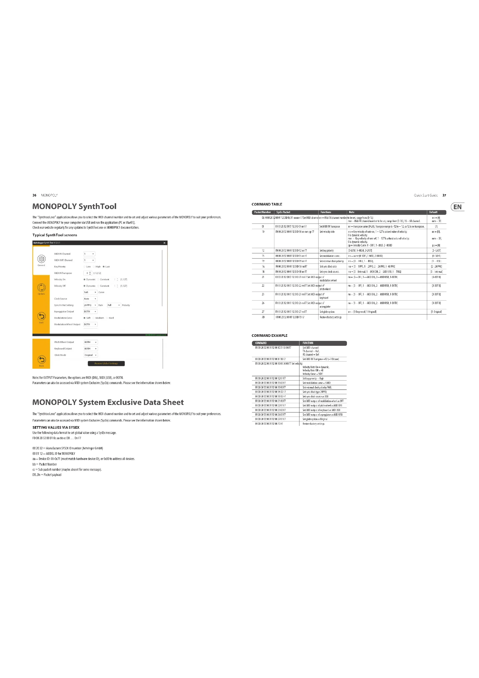
The "SynthioLoo" application allows you to select the MID channel number and to set and adjust various parameters of the MOKOPOLY to suit your preferences. Connect the MONOFLY to your computer via USB and run the application (PC or MacOS).
Check our website regularly for any updates to SynthTool,see or NHOPOPOLY documentation.
Typical SynthTool screens
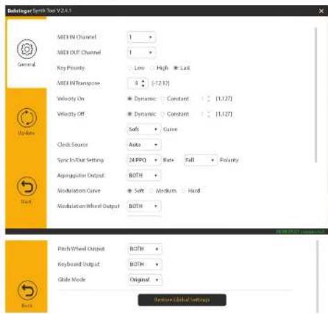
Note: for OUTPUT Parameters, the options are MIDI (BIN), MIDI (USB), or BOTH.
Parameters can also be accessed via MID system Exclusion (SysEx) commands. Please see the information shown below.
MONOPOLY System Exclusive Data Sheet
The "SynthiooLco" application allows you to select the MIDI channel number and to set and adjust various parameters of the KOKOPOLY to suit your preferences.
Parameters can also be accessed via MID system Exclusive (SysEx) commands. Please see the information shown below.
SETTING VALUES VIA SYSEX
Use the following data format to set global value using a SysEx message.
1000203200010caabccccc 00...0nF7
00.2032=ManufactureSYSDIDnumber(BbrgrerGmbH)
00-01.12=MOOELIDFORMCNPOPOLY
aa = Device ID: 00-0x7F (must match hardware device ID), or CoXO to address all devices.
bb = Packet Number
= 5 sub packet number (maybe absent for some message).
DO..Un = Packet payload
Quick Start Guide
37
COMMAND TABLE
| Packet Number | Splay Packet | Functions | Note | Default |
| 021000233 | 001120002111200168mF7 | Set MHT channel number | n= 5411 channel number n= 5411 channel number n= 5411 channel number n= 5411 channel number n= 5411 channel number n= 5411 channel number n= 5411 channel number n= 5411 channel number n= 5411 channel number n= 5411 channel number n= 5411 channel number n= 5411 channel number n-100T, -100D, -100B | n= [0]n=- [0] |
| 0F | 010201202121200168mF7 | Set MHT/Transgene | n= transgene value [0-1] Transgene range in 1.0 to 12, n= 12 of 12 transgene | [1] |
| 10 | 100020232001200168mmpp17 | Set service rate | n= key service rate, n= 127 b fixed value of service;0 is dynamic value;n=- 49 dynamic value at 1st, 1-127 b fixed value of service;0 is dynamic value;pP = elderly case 1-50T, 1-MCD, 2-MCD, 3-MCD | n=[0],n=- [0],n=- [0] |
| 12 | 100020232001200168mF7 | Set key priority | [0-100T, -1-200T, 2-MCD] | [1]-[10] |
| 15 | 100020232001200168mF7 | Set transmission cost | n=- [0-100T, -1-MCD, -2-MCD] | [0-100T] |
| 19 | 100020232001200168mF7 | Set external disk polarity | n=- [3-ALL, -1-MSL] | [1]-[100] |
| 18 | 100020232001200168mF7 | Set access disk rate | n=- [1-100T, -2-FI0T, 2-MCD, 3-MCD] | [2]-[200T] |
| 20 | 100020232001200168mF7 | Set packet count | n=- [1-Inter, 1-MCD, 2-MCD, 3-MCD, 4-MCD] | 0-Inter |
| 21 | 100202020211111111200168mF7 Set MHT output of mHT and mHT output of pHT and mHT | Output of mHT and mHT output of pHT and mHT | n=- [1-OFH, 1-MCD,1-MCD,2-MCD,3-MCD,4-MCD] | [1-MCD] |
| 22 | 100202020211111111200168mF7 Set MHT output of pHT and mHT | Output of pHT and mHT | n=- [1-OFH, 1-MCD,1-MCD,2-MCD,3-MCD,4-MCD] | [1-MCD] |
| 23 | 100202020211111111200168mF7 Set MHT output of kHpaand mHT | Output of kHpaand mHT | n=- [1-OFH, 1-MCD,1-MCD,2-MCD,3-MCD] | [1-MCD] |
| 26 | 100202020211111111200168mF7 Set MHT output of mHpaand mHT | Output of mHpaand mHT | n=- [1-OFH, 1-MCD,1-MCD,2-MCD,3-MCD,4-MCD] | [1-MCD] |
| 27 | 100202020211111111200168mF7 | Set glikapoplae | n=- [0-Inter, 1-Inter] | [1-Inter] |
| 70 | 100020232001200168mF7 | Restore latency settings |
COMMAND EXAMPLE
| COMMAND | FUNCTION |
| 00:20:20:00 12:00:00 21:04:07 | Set MDI channel |
| Set current = 0x1 | |
| Set channel = 0x1 | |
| 00:20:20:00 12:00:10 18:17 | Set MDI channel +12 (+10x2) |
| 00:20:20:00 12:00 10:30 30:00 7#Set selicity: | Velocity rate 0x- systematic Velocity rate 0x-48 Velocity rate = 10T |
| 00:20:20:00 12:00 12:31:12 | Set keypoint = High |
| 00:20:20:00 12:00 15:32:12 | Set resolution curve = 100 |
| 00:20:20:00 12:00 19:31:17 | Set external clock polarity FPLL |
| 00:20:20:00 12:00 16:32:17 | Set try/stop bit 24HPP |
| 00:20:20:00 12:00 13:32:17 | Set try/stop count 0x8B |
| 00:20:20:00 12:00 15:32:17 | Set MDI output of reference when as aOF |
| 00:20:20:00 12:00 20:32:17 | Set MDI output of offset when as MDI Off |
| 00:20:20:00 12:00 25:32:17 | Set MDI output of offset when MDI Off |
| 00:20:20:00 12:00 30:32:17 | Set MDI output of reference when MDI Off |
| 00:20:20:00 12:00 35:32:17 | Set reference options as Clamped |
| 00:20:20:00 12:00 40:32:17 | Reset secondary settings |
EN
| MONOPOLY Patch Sheet | Patch Number | |
| DATE: | AUTHOR: TITLE: | |
| NOTES: | ||
| MonoPoly | PORTAMENTO | MASTER TUNE | VCO1 | VCO2 | LEURS | OUTST | RESISTANCE | VCF | VCC | |||||
| OUTPUT | PERIOD | TIME | PWR | INTENSITY | FIR | DC TUNE | ATTACK | REACH | VCO2 | VCO3 | ||||
| ATTACK | WARTED MOS | 2 MHz | TRANSPORGE | ATTACK | REACH | VCO2 | VCO3 | |||||||
| ASPECT WHEEL | 100 MHz | |||||||||||||
| ASPECT WHEEL | ||||||||||||||

MONOPOLY Default Patch
| NOTES:The simplified settings shown below will help you get started making sounds, with VCO1 as a triangular waveform. Some control settings are shown with an arrow. These do not need to be on maximum, just as long as they are at least half-way or more, to get you started. |
| MonoPoly | PORTAMENTO | MASTR KITNE | VCO1 | ESTAGE | JUGS | CUTM | RESEARCE | REVERTURE | MEASURE | ||||
| OUTPUT | PWR | ATTERNANCE | |||||||||||
| WHEEL | TRANSPORGE | ||||||||||||
| ARPEDITOR | OKFIS EFFECTS | KEY ASSIN MODE | |||||||||||

| Synthetizer Architecture | ||
| Mode Chiral memory, uniform mono, 2000 shunt, pol | ||
| Type Analog | ||
| Oscillator 432.7Hz to 4.156Hz | ||
| LFO | ||
| MG1.0 Hz to 20Hz | ||
| MG2.0 Hz to 10Hz | ||
| MT flow pass filter, 24-bit flash, slope | ||
| Envelopes VCO, VCF | ||
| MIDI channels 16 | ||
| Connectivity | ||
| MEM in sync thru 5 pinCH | ||
| USB (MIDI) type 8 | ||
| Min output 1x1/4TS, unbalanced | ||
| Max outputlevel=64bit | ||
| Impedance 700Ω | ||
| Harshphone | 1x1/4T BIS stereo | |
| Max outputlevel 2.8bit | ||
| External control inputs | ||
| Appropriate synch | 1x1/4T BIS, Tippedox, Ring startstopsignal | |
| Paramemia | 1x1/4T TS, unbalanced | |
| VCO out/length mod | 1x1/4T TS, unbalanced, -5Vto +5V | |
| VCO freq mod | 1x1/4T TS, unbalanced, -5Vto +5V, 100V | |
| Triggerin | 1x1/4T TS, unbalanced | |
| CV in | 1x1/4T TS, unbalanced, 100V | |
| Internal control outputs | ||
| Triggerout x 1/4T TS, unbalanced | ||
| CVout | 1x1/4T TS, unbalanced, 100V | |
| Switching Propensity: 10V, ground | ||
| General Controls | ||
| Limits | Output volume: 0 to 10, adjustable | |
| Band wheel intensity: 0 to 10, adjustable | ||
| #651 wheel intensity: 0 to 10, adjustable | ||
| Parameter 0 to 10, adjustable | ||
| Aluwrature: 0 to 10, adjustable | ||
| General Controls | ||
| Switches | Output high level | |
| Band wheel: 0 to 10, low power: 1Vcf | ||
| #651 wheel: 0 to 10, low power: 1Vcf | ||
| Modulation | |
| Knobs | Mg1 frequency:0 to 10, adjustable |
| Switches | Mg1 waveform: triangular/reverse saw/crow/pulse, selectable |
| Mg3 frequency:0 to 10, adjustable | |
| FOM intensity: 0 to 10, adjustable | |
| PV intensity: 0 to 10, adjustable | |
| 4 mode: 0 to 10, adjustable | |
| Freq max: 0 to 10, adjustable | |
| PVR: efeg/mg/ring 2 | |
| Freq max: efeg/mg 3 | |
| Mode speed/s (k/s) max | |
| Mode single double | |
| LED (red) | Mg1 frequency |
| Mg2 frequency | |
| Appaggrator | |
| Switches | FID2 otores f otores |
| Iod down up cromm | |
| Ladle an off | |
| Effects | |
| Switch (with LED) | Effecrancy off |
| Key Assign Mode | |
| Switches (wirr LED) | Hotels |
| Cmod memory (micro) | |
| Uclear (micro) | |
| Uniclosure (poly) | |
| Poly | |
| Oscillator Bank | |
| Knobs | Tune (DC2.3 and 4) f adjustable |
| Switches (wirr LED) | Wireframe: triangular roccosse swl/own/pw, selectable |
| Outilace: 16, 8, 6, 2, selectable | |
| Levers: 0 to 10, adjustable | |
| LED (red) | WCI 1, 2, 3, 4 on |
| VCF Section | |
| Knobs | Goutfrecency 0 to 10, adjustable |
| Switches | Resonance: 0 to 10, adjustable |
| Gaininjection: 0 to +5, adjustable | |
| Sealback track: 0 to 100%, adjustable | |
| VCR Envelope Generator | |
| Knobs | Attrec time:0 to 10, adjustable |
| Desqtytime:0 to 10, adjustable | |
| Sustain level:0 to 10, adjustable | |
| Release time:0 to 10, adjustable | |
| VCR Envelope Generator | |
| Knobs | Attrec time:0 to 10, adjustable |
| Desqtytime:0 to 10, adjustable | |
| Sustain level:0 to 10, adjustable | |
| Release time:0 to 10, adjustable | |
| Lower Right Section | |
| Knobs | Isokin Level:0 to 10, adjustable |
| Switches | Togers single/multiple |
| Auto Connection off | |
| Keyboard and Wheels | |
| Wheels | Pitch |
| M6 T | |
| Keyboard | 32 semi-weighted, full-size keys with xerocity |
| USB | |
| Type Class-compliant USB 2.0, type B | |
| Supported operating systems | Windows 4.0 or higher |
| Mac OS X 10.6.8 or higher | |
| Power Requirements | |
| External power adaptor | 120kC 1000 mA |
| Power consumption | 9W max |
| Environmental | |
| Operating temperature range | 5℃ - 40℃ (17℉ - 104℉) |
| Physical | |
| Dimension (in×In×D) | 90×645×36 mm (3.5×25.5×14.2") |
| Weight | 10.3 kg (22.7 Kg) |
Other important information

Important information

Informations importantes

Responsible Party Name: Music Tribe Commercial NV Inc.
Address: 901 Grier Drive
Las Vegas, NV 89118
USA
Phone Number +1 747 237 5033
MONOPOLY
This equipment has been tested and found to comply with the limits for a Class 8 digital device, pursuant to part 15 of the FCC Rules. These limits are designed to provide reasonable protection against harmful interference in a residential installation. This equipment generates, uses and can radiate radio frequency energy and, if not installed and used in accordance with the instructions, may cause harmful interference to radio communications. However, there is no guarantee that interference will occur in a particular installation. If this equipment does cause harmful interference to radio or television reception, which can be determined by turning the equipment off and on, the user is encouraged to try to correct the interference by one or more of the following measures:
- Rerient or relocate the receiving antenna.
- Increase the separation between the equipment and receiver.
- Connect the equipment into an outlet on a circuit different from that to which the receiver is connected.
- Consult the dealer or an experienced radio TV technician for help.
This device complies with Part 15 of the FCC rules. Operation is subject to the following two conditions:
(1) this device may not cause harmful interference, and
(2) This device must accept any interference received, including interference that may cause undesired operation.
Important information:
Changes or modifications to the equipment not expressly approved by Music Title can aid the user's authority to use the equipment.
Quick Start Guide
We Hear You