
MT 820 - Lawn mower VIKING - Free user manual and instructions
Find the device manual for free MT 820 VIKING in PDF.
| Product type | Self-propelled lawn tractor (ride-on mower) |
| Brand | Viking |
| Model | MT 820 |
| Overall dimensions (L x W x H) | 172 x 126 x 104 cm |
| Wheelbase | 127 cm |
| Net weight | Tractor: 219 kg / Cutting deck: 55 kg |
| Engine | Briggs & Stratton Intek 28S707, 4-stroke, single-cylinder, 465 cm³, 9.7 kW (14.5 HP) |
| Transmission | Hydrostatic Tuff Torq K51 HC |
| Travel speed | Forward: 0 – 5.5 km/h / Reverse: 0 – 3.0 km/h |
| Fuel supply | Unleaded gasoline, tank 7.5 L |
| Battery | 12 V, 200 A (cold cranking) |
| Cutting width | 97 cm (38 inches) |
| Cutting height | 2.5 – 9.8 cm (adjustable) |
| Number of blades | 2 |
| Blade engagement | Power take-off (PTO) V-belt drive |
| Blade brake | Complete stop in less than 5 seconds after PTO disengagement |
| Tire pressure | Front: 0.83 – 1.04 bar / Rear: 0.69 – 0.83 bar |
| Safety system | Seat switch, PTO interlock, and parking brake |
| Sound level (LwA) | 100 dB(A) |
| Routine maintenance | Engine oil change, air filter, spark plug, belts, lubrication, battery cleaning |
| Spare parts available | Blades, belts, filters, spark plugs, batteries, tires |
| Warranty | 1 year (private use), 6 months (professional use) |
| Repairability | Simple adjustments possible by the user; major repairs at an authorized dealer |
Frequently Asked Questions - MT 820 VIKING
User questions about MT 820 VIKING
0 question about this device. Answer the ones you know or ask your own.
Ask a new question about this device
Download the instructions for your Lawn mower in PDF format for free! Find your manual MT 820 - VIKING and take your electronic device back in hand. On this page are published all the documents necessary for the use of your device. MT 820 by VIKING.
USER MANUAL MT 820 VIKING
natural_image
White and black robotic lawn tractor with visible branding (VIKING MT 820), no text or symbols on the vehicle body.Thank you for deciding to purchase a quality appli-ance from VIKING.
This appliance is manufactured using the most up-to-date production techniques and comprehensive quality assurance procedures. Our aim is to ensure that you are 100% satisfied.
If you have any queries about your appliance please direct them to your retailer or directly to our marketing company.
I hope you will be completely satisfied with your VIKING appliance
Signed

Nikolas Stihl
Managing Director
Identification Numbers ......2
Safety Rules & Information ....4
Assembly....7
Unpacking 7
Fitting the Seat....7
Fitting the Wheels 8
Fitting the Steering Wheel 10
Moving the Traktor from the Pallet .....11
Assembling the Mowerdeck ....11
Activating the Batterie ....13
Features & Controls....14
Control Functions....14
Safety Interlock System Test....15
Operating the Tractor....16
General 16
Checks Before Starting....16
Clutch/Brake Pedal Operation....17
Starting the Engine ....17
Stopping the Tractor & Engine....17
Driving the Tractor....18
Mowing....18
Pushing the Tractor by Hand 19
Attaching a trailer....14
Mower Deck Removal & Installation .....20
Removing the Mower Deck....20
Installing the Mower Deck....21
Mower Cutting Height Adjustment .....21
Storage....22
Starting after a long Term Storage ....22
Regular Maintenance ....23
Maintenance Schedule 23
Raising the Hood & Seat 24
Checking/Adding Fuel....24
Checking Tire Pressures....24
Check / Replace Fuel Filter 25
Engine Maintenance ....25
Blade Brake Check 25
Safety Interlock System Check....25
Hydro Transmission Service 26
Exhaust Screen Service 27
Battery Maintenance....27
Lubrication 28
Lubricate Rear Axel Shafts....29
Servicing the Mower Blades 30
Common replacement parts ....31
Maintenance Records....31
Troubleshooting, Adjustments & Service.....32
Troubleshooting the Tractor....32
Troubleshooting the Mower....33
Seat Adjustment....34
Steering Gear Adjustment ....34
Brake & Brake Spring Adjustment ....34
Mower Adjustments 35
PTO Clutch Adjustment 35
Leveling the Mower....36
Blade Brake Check 37
Mower Belt Replacement....38
Tractor Drive Belt Replacement ....39
Battery Service 40
Checking the Battery Voltage 40
Charging A Discharged Battery 40
Jump Starting with an Auxiliary Battery......40
Transmission Purging....42
Specifications 43
Common International Symbols ....44
Certificate of Conformity 45
Note: In this manual, "left" and "right" are referred to as seen from the operating position.

WARNING

Engine exhaust from this product contains chemicals known, in certain quantities, to cause cancer, birth defects, or other reproductive harm.
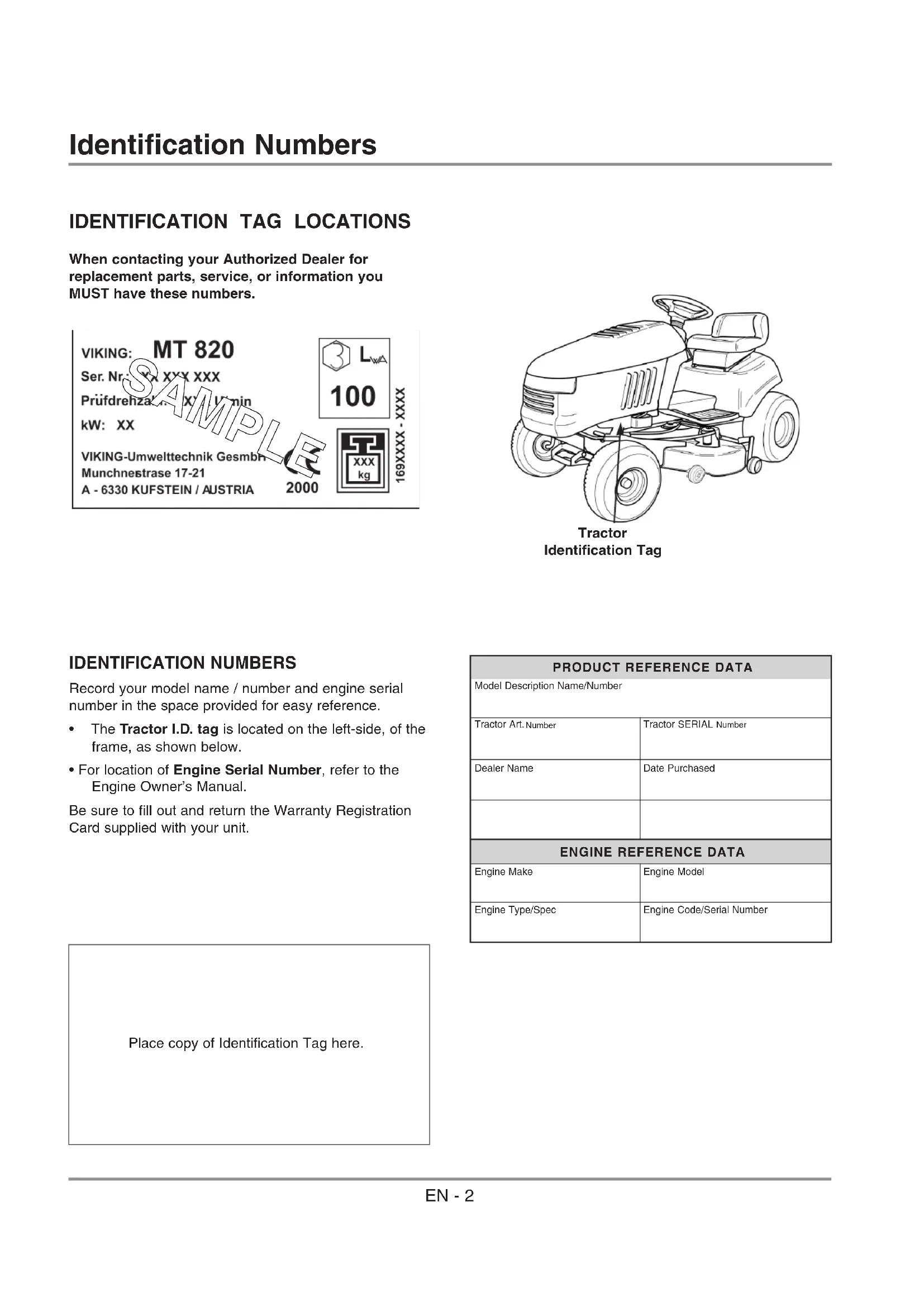
IDENTIFICATION TAG LOCATIONS
When contacting your Authorized Dealer for replacement parts, service, or information you MUST have these numbers.

natural_image
Line drawing of a grassy tractor with visible wheels and steering wheel (no text or symbols)Tractor Identification Tag
IDENTIFICATION NUMBERS
Record your model name / number and engine serial number in the space provided for easy reference.
- The Tractor I.D. tag is located on the left-side, of the frame, as shown below.
- For location of Engine Serial Number, refer to the Engine Owner's Manual.
Be sure to fill out and return the Warranty Registration Card supplied with your unit.
| PRODUCT REFERENCE DATA | |
| Model Description Name/Number | |
| Tractor Art.Number | Tractor SERIAL Number |
| Dealer Name | Date Purchased |
| ENGINE REFERENCE DATA | |
| Engine Make | Engine Model |
| Engine Type/Spec | Engine Code/Serial Number |
Place copy of Identification Tag here.
IDENTIFICATION TAG MARKINGS

- Type of lawntractor
- Serial number
- Test speed in rotations per minute
- Power rating in kilowatts
-
Name and adress of manufacturer
-
Conformity mark according to directive 98/37/EWG
- Year of manufacture
- Weight in kilograms
- Sound power level in decibels

Read these safety rules and follow them closely. Failure to obey these rules could result in loss of control of unit, severe personal injury or death to you, or bystanders, or damage to property or equipment. This mowing deck is capable of amputating hands and feet and throwing objects. The triangle ⚠️ in text signifies important cautions or warnings which must be followed.

GENERAL OPERATION
- Read, understand, and follow all instructions in the manual and on the unit before starting.
- Only allow responsible adults, who are familiar with the instructions, to operate the unit.
- Clear the area of objects such as rocks, toys, wire, etc., which could be picked up and thrown by the blade(s).
- Be sure the area is clear of other people before mowing. Stop unit if anyone enters the area.
- Never carry passengers.
- Do not mow in reverse unless absolutely necessary. Always look down and behind before and while travelling in reverse.
- Be aware of the mower discharge direction and do not point it at anyone. Do not operate the mower without either the entire grass catcher or the deflector in place.
- Slow down before turning.
- Never leave a running unit unattended. Always disengage the PTO, set parking brake, stop engine, and remove keys before dismounting.
- Disengage the PTO lever to stop the blades when not mowing.
- Stop engine before removing grass catcher or unclogging chute.
- Mow only in daylight or good artificial light.
- Do not operate the unit while under the influence of alcohol or drugs.
- Watch for traffic when operating near or crossing roadways.
- Use extra care when loading or unloading the unit into a trailer or truck.
- Data indicates the operators, age 60 years and above, are involved in a large percentage of riding mower-related injuries. These operators should evaluate their ability to operate the riding mower safely enough to protect themselves and others from injury.
- Keep in mind the operator is responsible for accidents occurring to other people or property.
- All drivers should seek and obtain professional and practical instruction.
- Always wear substantial footwear and trousers. Never operate when barefoot or wearing sandals.
- Before using, always visually check that the blades and blade hardware are present, in-tact, and secure. Replace worn or damaged parts.
- Never operate the machine with defective guards, or without safety protective devises in place.
- Disengage attachments before: refuelling, removing an attachment, making adjustments (unless the adjustment can be made from the operator's position).
- When the machine is parked, stored, or left unattended, lower the cutting means unless a positive mechanical lock is used.
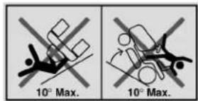
SLOPE OPERATION

WARNING

Never operate on slopes greater than 17,6 percent ( 10^ ) which is a rise of 1m vertically in 6m horizontally. When operating on slopes use additional wheel weights or counterweights. See your dealer to determine which weights which weights are available and appropriate for your unit. Select slow ground speed before driving onto slope. In addition to front and rear weights, use extra caution when operating on slopes with rear-mounted grass catcher. Mow UP and DOWN the slope, never across the face, use caution when changing directions and DO NOT START OR STOP ON SLOPE.
Slopes are a major factor related to loss-of-control and tip-over accidents, which can result in severe injury or death. All slopes require extra caution. If you cannot back up the slope or if you feel uneasy on it, do not drive on it.
Control of a ride-on machine sliding on a slope will not be regained by the application of the brake. The main reasons for loss of control are: insufficient tire grip on the ground, speed too fast, inadequate braking, the type of machine is unsuitable for it's task, lack of awareness of the ground conditions, incorrect hitching and load distribution.
Do
- See your authorized dealer for recommendations of available weights to improve stability.
- Mow up and down slopes, not across.
- Remove obstacles such as rocks, tree limbs, etc.
- Watch for holes, ruts, or bumps. Uneven terrain could overturn the unit. Tall grass can hide obstacles.
- Use slow speed. Choose a low gear so that you will not have to stop or shift while on the slope.
- Use extra care with grass catchers or other attachments. These can change the stability of the unit.
- Keep all movement on the slopes slow and gradual. Do not make sudden changes in speed or direction.
Do Not
- Do not start or stop on a slope. If tires lose traction, disengage the blade(s) and proceed slowly straight down the slope.
- Do not turn on slopes unless necessary, and then, turn slowly and gradually uphill, if possible.
- Do not mow near drop-offs, ditches, or embankments. The mower could suddenly turn over if a wheel is over the edge of a cliff or ditch, or if an edge caves in.
- Do not mow on wet grass. Reduced traction could cause sliding.
- Do not try to stabilize the unit by putting your foot on the ground.
- Do not use grass catcher on steep slopes.
CHILDREN
Tragic accidents can occur if the operator is not alert to the presence of children. Children are often attracted to the unit and the mowing activity. Never assume that children will remain where you last saw them.
- Keep children out of the mowing area and under the watchful care of another responsible adult.
- Be alert and turn unit off if children enter the area.
- Before and during reverse operation, look behind and down for small children.
- Never carry children. They may fall off and be seriously injured or interfere with safe unit operation.
- Never allow children to operate the unit.
- Use extra care when approaching blind corners, shrubs, trees, or other objects that may obscure vision.
TRANSPORTING AND STORAGE
- Always observe safe refueling and fuel handling practices when refueling the unit after transportation or storage.
- Always follow the engine manual instructions for storage preparations before storing the unit for both short and long term periods.
- Always follow the engine manual instructions for proper start-up procedures when returning the unit to service.
- Never store the unit or fuel container inside where there is an open flame or pilot light, such as in a water heater. Allow unit to cool before storing.

WARNING

When transporting this tractor on an open trailer, make sure unit is facing forward, toward the direction of travel. If tractor is facing backward, wind lift could cause damage to the hood.
SERVICE AND MAINTENANCE
- Use extra care in handling gasoline and other fuels. They are flammable and vapors are explosive.
a) Use only an approved container.
b) Never remove gas cap or add fuel with the engine running. Allow engine to cool before refueling. Do not smoke.
c) Never refuel the unit indoors.
- Never run a unit in an enclosed area.
- Keep nuts and bolts, especially blade attachment bolts, tight and keep equipment in good condition.
- Never tamper with safety devices. Check their proper operation regularl and make necessary repairs if they are not functioning properly.y.
-
Keep unit free of grass, leaves, or other debris build-up. Clean up oil or fuel spillage.
-
Stop and inspect the equipment if you strike an object. Repair, if necessary, before restarting.
- Never make adjustments or repairs with the engine running unless specified otherwise in the engine manufacturer's manual.
- Grass catcher components are subject to wear, damage, and deterioration, which could expose moving parts or allow objects to be thrown. Frequently check components and replace with manufacturer's recommended parts, when necessary.
- Mower blades are sharp and can cut. Wrap the blade(s) or wear gloves, and use extra caution when servicing them.
- Check brake operation frequently. Adjust and service as required.
- Use only factory authorized replacement parts when making repairs.
- Always comply with factory specifications on all settings and adjustments.
- Only authorized service locations should be utilized for major service and repair requirements.
- Never attempt to make major repairs on this unit unless you have been properly trained. Improper service procedures can result in hazardous operation, equipment damage and voiding of manufacturer's warranty.
- If fuel is spilled, do not attempt to start the engine but move the machine away from the area of spillage and avoid creating any source of ignition until petrol vapors have dissipated.
- Replace all fuel tank caps and fuel container caps securely.
- On multiple blade mowers, take care as rotating one blade can cause other blades to rotate.
- Do not change engine governor settings or over-speed the engine. Operating the engine at excessive speed can increase the hazard of personal injury.
- Disengage drive attachments, stop the engine, remove the key, and disconnect the spark plug wire(s) before: clearing attachment blockages and chutes, performing service work, striking an object, or if the unit vibrates abnormally. After striking an object, inspect the machine for damage and make repairs before restarting and operating the equipment.
- Never place hands near the hydro pump cooling fan when the unit is running. Cooling fan is located on top of transaxle.
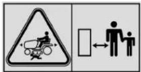
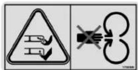
SAFETY DECALS
This unit has been designed and manufactured to provide you with the safety and reliability you would expect from an industry leader in outdoor power equipment manufacturing.
Although reading this manual and the safety instructions it contains will provide you with the necessary basic knowledge to operate this equipment safely and effectively, we have placed several safety labels on the unit to remind you of this important information while you are operating your unit.
All DANGER, WARNING, CAUTION and instructional messages on your rider and mower should be carefully read and obeyed. Personal bodily injury can result when these instructions are not followed. The information is for your safety and it is important! The safety decals below are on your rider and mower.
If any of these decals are lost or damaged, replace them at once. See your local dealer for replacements.
These labels are easily applied and will act as a constant visual reminder to you, and others who may use the equipment, to follow the safety instructions necessary for safe, effective operation.
Warning: Read Operator's Manual.
Read and understand the Operator's Manual before using this machine

Danger: Thrown Ogjects.
This machine is capable of throwing objects and debris. Keep bystanders away.

Warning: Remove Key Before Servicing.
Remove the key and consult technical literature before performing repairs or maintenance.

Danger: Machine Rollover.
Do not use this machine on slopes greater than 10^ .
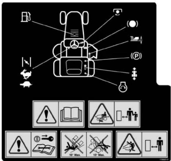
Decal - Operating Instructions
Decal - Danger
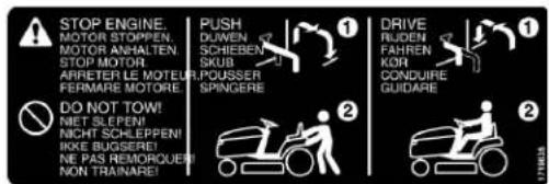
Decal - Hydro Release Valve
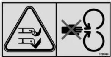
Danger: Dismemberment.
This machine can amputate limbs. Keep bystanders and children away when engine is running.
Danger: Dismemberment.
This mower deck can amputate limbs. Keep hands and feet away from blades.
For storage and transport reasons, some components of the tractor are not directly installed in the factory, but have to be assembled after their removal from the packing. Final assembly is carried out by following these simple instructions.

CAUTION

For transport reasons the lawntractor is supplied without engine oil or fuel. Before starting up the engine, fill with oil and fuel following the instructions given in the engine Operator's Manual
UNPACKING
When unpacking the tractor, take care to gather all individual parts and fittings.
The standard packing contents: - tractor
- steering wheel
- seat
- mower deck
- wheels
- an envelope containing the Owner's Manual, documents, washers, spacers, e-rings, feather keys and caps, two starter keys, a pin for blocking the steering wheel.
FITTING THE SEAT
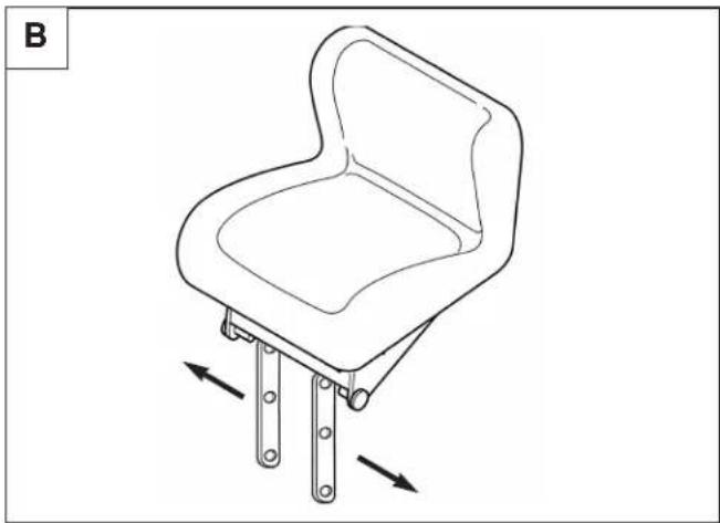
natural_image
Line drawing of a chair with two metal legs and a curved seat, showing directional arrows indicating movement (no text or symbols)Assembly

natural_image
Mechanical assembly diagram showing lever mechanism and component layout (no readable text or symbols)
FITTING THE WHEELS
Rear wheels
natural_image
Line drawing of hands using pliers to adjust or install a mechanical component (no text or symbols)
natural_image
Mechanical assembly diagram showing a lifting mechanism with ropes and a directional arrow (no text or labels)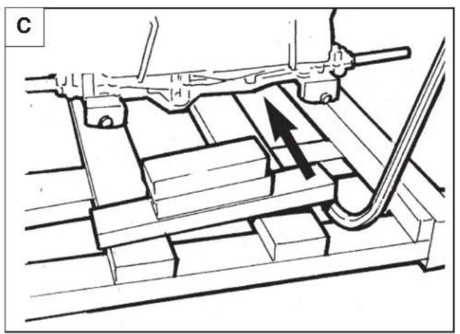
natural_image
Technical diagram of a mechanical assembly with no visible text or symbols
natural_image
Mechanical assembly diagram showing a shaft and housing with a directional arrow indicating motion (no text or symbols)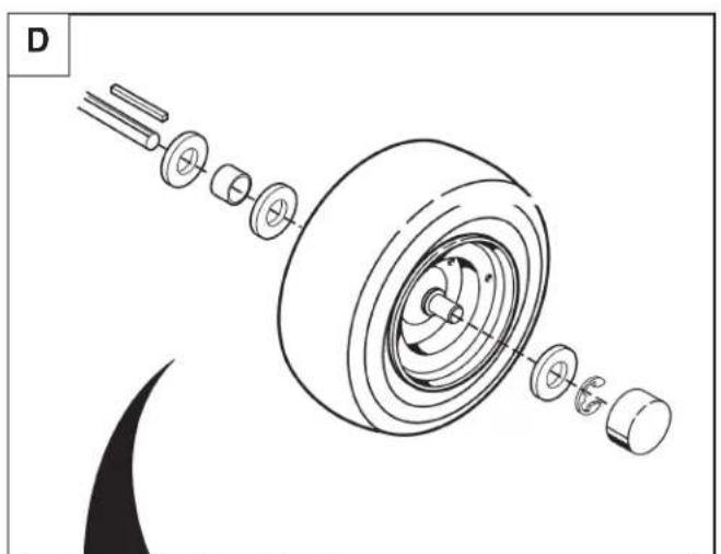
natural_image
Exploded view diagram of a mechanical assembly showing components like gears and shafts (no text or labels)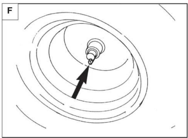
natural_image
Diagram showing concentric curved lines with a black arrow pointing to a small circular feature, labeled 'F' in the top-left corner (no text or symbols within the diagram itself)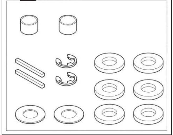
natural_image
Collection of mechanical washers and cylindrical components (no text or labels)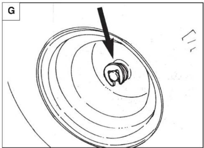
natural_image
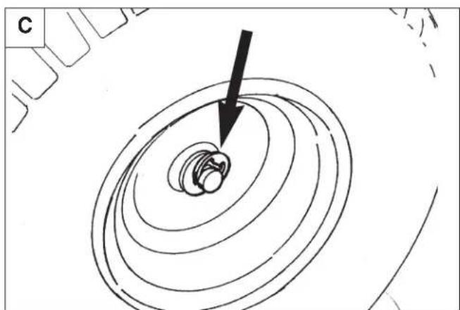
Diagram of concentric circular patterns with a black arrow pointing to a small circular feature, no text or symbols present.Note: Install all tires with valve stem facing in toward the tractor.
Front wheels
natural_image
Diagram showing concentric circular layers with a black arrow pointing to a small circular feature, no text or symbols present.
Note: Install all tires with valve stem facing in toward the tractor.
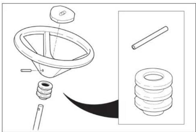
FITTING THE STEERING WHEEL
Put the tractor on a flat surface and straighten up the front wheels. Fit the steering wheel onto the protruding shaft with the spokes directed towards the seat.
Line up the whole in the steering wheel hub with the hole in the shaft and insert the pin supplied.
natural_image
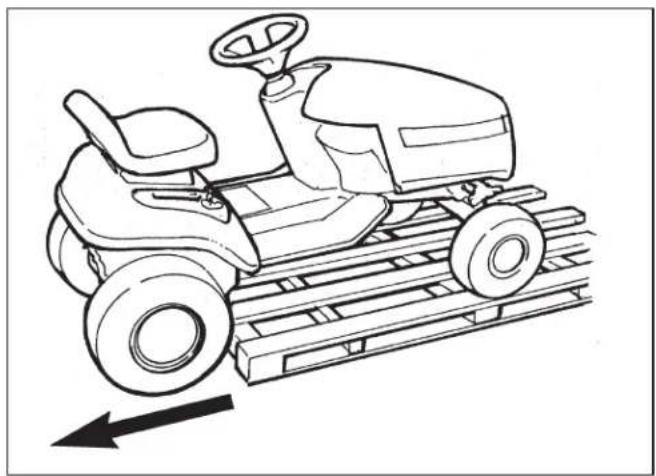
Technical line drawing of a mechanical component with no visible text or symbolsMOVING THE TRACTOR FROM THE PALLET
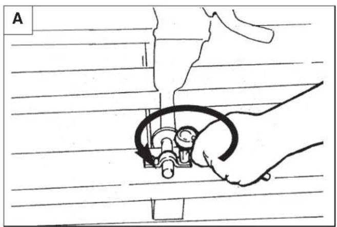
To make it easier to get the tractor off the pallet and to move it, the Transmission Release Valve Lever should be put into released position. (See Pushing the Tractor by Hand in the Operating the Tractor Section)
natural_image
Line drawing of a tractor on a ramp with an arrow indicating speed (no text or symbols)ASSEMBLING THE MOWERDECK

natural_image
Technical line drawing of a mechanical device with internal components and an arrow indicating direction (no text or symbols)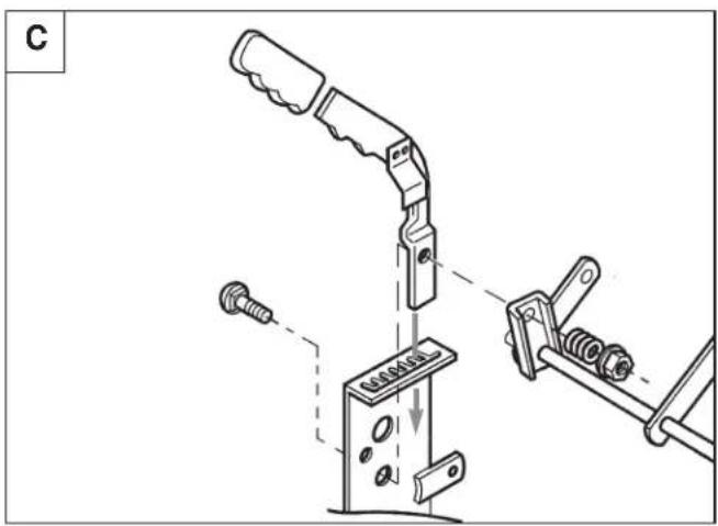

natural_image
Technical line drawing of a mechanical assembly with a tool and circular component (no text or symbols)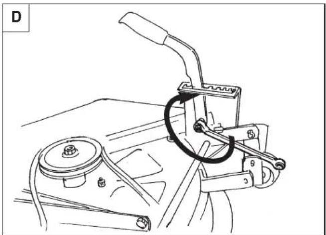
natural_image
Technical line drawing of a mechanical lever assembly with no visible text or symbolsAssembly

natural_image
Technical line drawing of a mechanical assembly with bolts and brackets (no text or symbols)

natural_image
Technical line drawing of a mechanical linkage assembly (no text or symbols)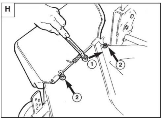
For installing the mower deck on the tractor see Installing the Mower Deck in the Operating the Tractor Section.
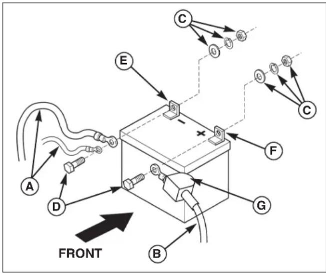
ACTIVATE THE BATTERY

WARNING

Be careful when handling the battery. Keep flames and sparks away from the battery.
When removing or installing battery cables, disconnect the negative cable FIRST and reconnect it LAST. If not done in this order, the positive terminal can be shorted to the frame by a tool.
The battery is situated in a compartment under the seat.
- Remove the battery from the battery compartment.
- Charge battery for 1 hour at 6-10 amps.
- Reinstall the battery in the battery compartment.
- First, connect the positive battery cable (B) to the positive battery terminal (F). Slide the terminal cover (G) into place. Second, connect the negative battery cable (A) to the negative battery terminal (E).
Position the positive battery cable over seat switch harness to prevent harness from becoming pinched in seat pivot. Make sure that protective terminal cover is in place over positive battery post. (See also Battery Installation in the Regular Maintenance Section)
flowchart
graph TD
    A["A"] --> B["D"]
    B --> C["E"]
    C --> D["F"]
    D --> E["C"]
    E --> F["F"]
    F --> G["G"]
    G --> H["B"]
    H --> I["FRONT"]
    style A fill:#f9f,stroke:#333
    style B fill:#f9f,stroke:#333
    style C fill:#ccf,stroke:#333
    style D fill:#ccf,stroke:#333
    style E fill:#ccf,stroke:#333
    style F fill:#ccf,stroke:#333
    style G fill:#ccf,stroke:#333
    style H fill:#ccf,stroke:#333
    style I fill:#ccf,stroke:#333
Please take a moment and familiarize yourself with the name, location, and function of these controls so that you will better understand the safety and operating instructions provided in this manual.
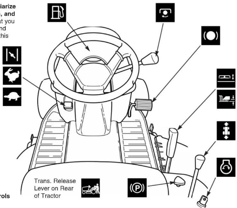
Figure 1. Tractor & Mower Controls
CONTROL FUNCTIONS
The information below briefly describes the function of individual controls. Starting, stopping, driving, and mowing require the combined use of several controls applied in specific sequences. To learn what combination and sequence of controls to use for various tasks see the OPERATION section.


Throttle / Choke Control
The throttle controls engine speed. Move the throttle up to increase engine speed and down to decrease engine speed. Always operate at FULL throttle.
Note: Moving the throttle control fully forward closes the choke. A warm engine may not require choking.

PTO Lever
The PTO (Power Take-Off) lever engages and disengages the blades. To engage the PTO, move the lever forward. To disengage the PTO, move the lever all the way back. You will feel the lever lock into both the engaged and disengaged positions.
Note: The operator must be seated firmly in the tractor seat for the PTO to function. Also note that the tractor will not start unless the lever is in the disengaged position.

Ground Speed Control Lever
The tractor's forward & reverse ground speed is controlled by the ground speed control lever.
The ground speed is selected from a continuous range. Moving the lever forward in the F range increases FORWARD tractor motion, and moving the lever back in the R range increases REVERSE tractor motion. The further the lever is moved in either range, the faster the tractor will travel in that direction.
Note: Depressing the clutch/brake pedal is NOT necessary when changing speeds or directions. Placing the lever in the N position puts the transmission in NEUTRAL, and ceases tractor motion. (Apply & set the Parking Brake before leaving the operator's position).
Always mow with the engine speed at full throttle. Note: If the terrain is rough, hilly, or sloping, use a slower forward speed. If the grass is wet or over 76 mm high, use full engine speed with a low forward speed so the mower will have enough power to cut the grass.

Clutch/ Brake Pedal
Depressing the clutch/ brake pedal disengages the transmission drive and applies the tractor brake.

Parking Brake Control Knob
Engages parking brake. Depress clutch/ brake pedal fully and pull up knob to engage parking brake. To disengage brake, depress pedal and push knob down.

Fuel fill
See Checking / Adding Fuel in the Regular Maintenance Section.


Mower Cutting Height Lever
The cutting height adjustment lever controls the mower cutting height. Set the mower deck in the highest cutting position when transporting to and from the mowing site.

Ignition Switch
The ignition switch starts and stops the engine, it has three positions:
OFF Stops the engine and shuts off the electrical system.
RUN Allows the engine to run and powers the electrical system.
START Cranks the engine for starting.
Note: Never leave the ignition switch in the RUN position with the engine stopped-this drains the battery.

Transmission Release Valve Lever
See Pushing the Tractor by Hand in the Operating the Tractor Section.
Steering Wheel
The steering wheel controls the direction of the tractor's travel by angling the front wheels.
This unit is equipped with safety interlock switches and other safety devices. These safety systems are present for your safety: do not attempt to bypass safety switches, and never tamper with safety devices. Check their operation regularly.
Operational SAFETY Checks
Your unit is equipped with a seat switch safety system. Check the seat switch operation every fall and spring with the following tests.
Test 1 — Engine should NOT crank if:
- PTO lever is ENGAGED, OR
- Brake pedal is NOT fully depressed (parking brake OFF)
Test 2 — Engine SHOULD crank if:
- PTO lever is DISENGAGED, AND
- Brake pedal is fully depressed (parking brake ON)
Test 3 — Engine should SHUT OFF if:
• The Operator rises off seat
Test 4 — Blade Brake Check
- Mower blades and mower drive belt should come to a complete stop within five seconds after PTO is turned OFF (or operator rises off seat). If mower drive belt does not stop within five seconds, readjust the PTO clutch as described in the ADJUSTMENTS section or see your dealer.
Note: Once the engine has stopped, the PTO must be turned off after the operator returns to the seat in order to start the engine.

WARNING

If the unit does not pass a safety test, do not operate it. See your authorized dealer. Under no circumstance should you attempt to defeat the purpose of the safety interlock system.
GENERAL OPERATING SAFETY
Before first time operation:
- Be sure to read all information in the Safety and Operation sections before attempting to operate this tractor and mower.
- Become familiar with all of the controls and how to stop the unit.
- Drive in an open area without mowing to become accustomed to the unit.
natural_image
Illustration of a person standing beside a cleaning robot with a tool, no text or symbols present
WARNING

Never allow passengers to ride on the unit.
Before leaving the operator's position for any reason, engage the parking brake, disengage the PTO, stop the engine and remove the key.
To reduce fire hazard, keep the engine, tractor and mower free of grass, leaves and excess grease. Do not stop or park tractor over dry leaves, grass or combustible materials.
Gasoline is highly flammable and must be handled with care. Never fill the tank when the engine is still hot from recent operation. Do not allow open flame, smoking or matches in the area. Avoid over-filling and wipe up any spills.
CHECKS BEFORE STARTING
- Check that the crankcase is filled with oil to full mark on dipstick. See the engine Operator's Manual for instructions and oil recommendations.
- Make sure all nuts, bolts, screws and pins are in place and tight.
- Adjust the seat position, and make certain you can reach all controls from operator's position.
- Fill the gasoline tank with fresh gasoline. Refer to engine manual for gasoline recommendations.
- Make certain rear counterweights are installed if you will be operating the unit on sloping ground.

DANGER

Never operate on slopes greater than 17,6 percent ( 10^ ) which is a rise of 1m vertically in 6m horizontally. When operating on slopes use additional wheel weights or counterweights. See your dealer to determine which weights which weights are available and appropriate for your unit. Select slow ground speed before driving onto slope. In addition to front and rear weights, use extra caution when operating on slopes with rear-mounted grass catcher.
Mow UP and DOWN the slope, never across the face, use caution when changing directions and DO NOT START OR STOP ON SLOPE.
- Depressing the clutch/brake pedal (A, Figure 2) disengages the transmission drive. Fully depressing the pedal applies the rider brake.
- Parking brake is applied by pulling up on the parking brake control knob (B, Figure 2) with the clutch/brake pedal fully depressed.
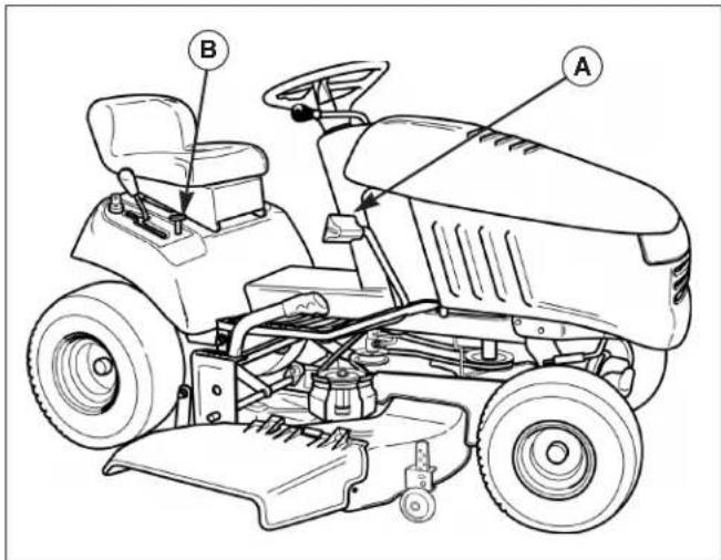
Figure 2. Clutch/ Brake Pedal Operation
A. Clutch/Brake Pedal
B. Parking Brake Control Knob
STARTING THE ENGINE
- While sitting in the operator's seat, fully depress the brake pedal or set the parking brake.
- Make sure that the ground speed control lever is in NEUTRAL.
- Disengage the PTO clutch.
- Set throttle to CHOKE.
Note: A warm engine may not require choking.
5. Insert the ignition key and turn it to START.
6. After the engine starts, move the engine throttle control to SLOW. Warm up the engine by running it for at least a minute before engaging the PTO or driving the tractor.
Note: In the event of an emergency the engine can be stopped by simply turning the ignition switch to STOP. Use this method only in emergency situations. For normal engine shut down follow the procedure given in STOPPING THE TRACTOR.

WARNING

If you do not understand how a specific control functions, or have not yet thoroughly read the FEATURES & CONTROLS section, do so now. Do NOT attempt to operate the tractor without first becoming familiar with the location and function of ALL controls.
STOPPING THE TRACTOR & ENGINE
-
Returning the ground speed lever to NEUTRAL will stop tractor movement. For emergency stopping of any model, FULLY depress the clutch/ brake pedal to apply the tractor brake.
-
Engage the parking brake.
- Disengage the PTO.
- Position the throttle control at FULL.
- Turn the ignition switch to OFF and remove the key.
Note: Stopping the engine at speeds lower than full throttle can cause engine damage. Do not stop the engine with the throttle control in the IDLE position.

WARNING

Tragic accidents can occur if the operator is not alert to the presence of children. Children are often attracted to the unit and the mowing activity. Never assume that children will remain where you last saw them.
- Keep children out of the mowing area and under the watchful care of another responsible adult.
- Be alert and turn unit off if children enter the area.
- Before and during reverse operation, look behind and down for small children.
- Never carry children. They may fall off and be seriously injured or interfere with safe unit operation.
- Never allow children to operate the unit.
- Use extra care when approaching blind corners, shrubs, trees, or other objects that may obscure vision.

natural_image
Illustration of a family cleaning a small electric tool with an adult guiding them (no text or symbols)DRIVING THE TRACTOR
- Sit in the seat and adjust the seat so that you can comfortably reach all the controls (see Seat Adjustment, Adjustments Section).
- Engage the parking brake.
- Make sure the PTO lever is disengaged.
- Start the engine (see STARTING THE ENGINE).
- Be sure the ground speed lever is in the NEUTRAL position.
- Release the parking brake by depressing the clutch/brake pedal and pushing the parking brake knob down. Release the clutch brake pedal.
- Move the ground speed lever forward until the desired ground speed is achieved. There is no need to clutch when changing speeds or direction.
MOWING
- Engage the parking brake. Make sure the PTO lever is disengaged.
- Start the engine (see STARTING THE ENGINE).
- Set the mower cutting height to the desired level.
- Set the throttle to FULL.
- Engage the PTO.
- Begin mowing. See the LAWN CARE & MOWING INFORMATION section at the back of this manual for tips on mowing patterns, lawn care, and troubleshooting information.
- When finished, shut off the PTO.
- Stop the engine (see STOPPING THE TRACTOR AND ENGINE).

WARNING

Make certain the area of operation, and especially the direction of travel is clear of objects, people and animals.
Always look DOWN AND BEHIND before backing!

natural_image
Illustration of a person using a tennis racket on a wheeled cart near a tree, with another person standing nearby (no text or symbols)PUSHING THE TRACTOR BY HAND
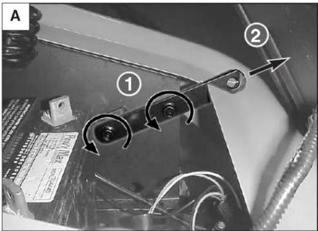
- Disengage the PTO and turn the engine off.
- Move the transmission release lever up, pull back approximately 25 mm, and press down to lock into released position (Figure 3).
- The tractor can now be pushed by hand.
Note: To drive the tractor, the release lever must be moved completely forward and pushed down into locked position.

DO NOT TOW TRACTOR
Towing the unit will cause transmission damage.
- Do not use another vehicle to push or pull this unit.
- Do not actuate the transmission release valve lever while the engine is running.
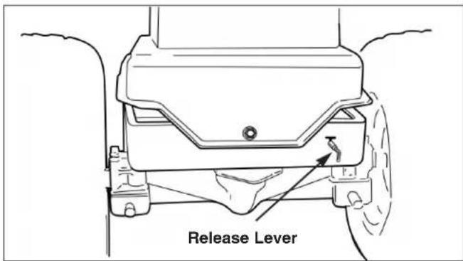
Figure 3. Release Lever
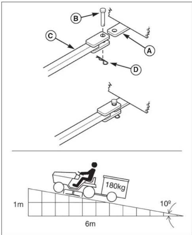
ATTACHING A TRAILER
The maximum horizontal drawbar force allowed is 444N.
The maximum vertical drawbar force is 222N.
This equates to a 180 kg trailer on a 10° hill.
- Align the trailer tongue (C) with the trailer hitch (A). Secure using a clevis pin (B) and hair pin clip (D).
MOWER DECK REMOVAL & INSTALLATION

WARNING

Engage parking brake, disengage PTO, stop engine, disconnect spark plug wire(s), and remove key before attempting to install or remove the mower.

CAUTION

The muffler and surrounding areas may be hot.
Removing the Mower Deck
Note: Perform mower removal on a hard, level surface such as a concrete floor.
-
Park the tractor, disengage the PTO lever, turn off the engine, remove the key, disconnect the spark plug wire(s), and engage the parking brake.
-
Place mower in the lowest cutting position using the mower height adjustment lever (A, Figure 4).
-
Remove the mower belt from the engine pulley (D, Figure 4) by flexing the engine belt guide rearward slightly, and pulling the belt off the pulley.
-
Remove the hair pin clip from the clutch rod (C, Figure 4).
-
Remove the clutch rod (C, Figure 4) from the bottom of the PTO lever (B). Reinstall the hair pin clip removed in the previous step.
-
Remove the hair pin clip from the long hitch rod (A, Figure 5).
-
Remove the hitch rod (A, Figure 5) from the mower.
-
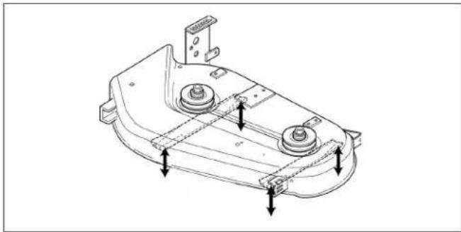
Turn wheels straight ahead. Pull back on spring-loaded lever (B, Figure 6) and lift mower hitch off of the tractor bracket (A).
-
Turn wheels fully left, and slide mower deck out from under the right side of the tractor. Reinstall the hitch rod and hair pin clip (A, Figure 5) in the mower.
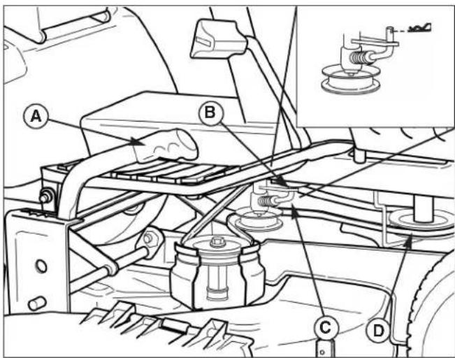
Figure 4. Mower Deck - Right Side
A. Height Adj. Lever C. Clutch Rod
B. Bottom of PTO Lever D. Engine Pulley
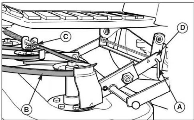
Figure 5. Mower Deck - Right Side
A. Long Hitch Rod & Hair Pin Clip C. Clutch Rod B. Mower Drive Belt D. Rear Hitch Brackets
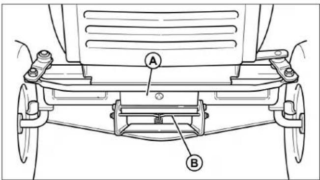
Figure 6. Mower Deck - Right Side
A. Tractor Hitch Brackets B. Spring-Loaded Lever
Installing the Mower Deck
Note: Perform mower installation on a hard, level surface such as a concrete floor.
- Park the tractor, disengage the PTO lever, turn off the engine, remove the key, disconnect the spark plug wire(s), and engage the parking brake.
- Place mower in the lowest cutting position using the cutting height adjustment lever (A, Figure 7).
- Turn the wheels left, and slide the mower deck under the tractor.
- Turn the wheels straight ahead and align the rear mounting brackets (D, Figure 5).
- Pull the spring-loaded lever (B, Figure 6) forward, hook the mower hitch on the tractor bracket (A). Release the spring loaded lever to lock the mower hitch in the tractor bracket.
- Install the long hitch pin (A, Figure 5) through the rear mounting brackets. Secure with a hair pin clip.
Note: If the rear mounting bracket holes are not aligned, shift the mower deck and turn the front wheels slightly.
- Install the mower drive belt (B, Figure 7) on the engine pulley; flex the engine belt guide rearward slightly to get the belt onto the pulley.
- Connect the clutch rod (C, Figure 4) to the bottom of the PTO lever (B). Secure using a hair pin clip.
- Check the PTO adjustment (see PTO Clutch Adjustment in the Adjustment Section).
MOWER CUTTING HEIGHT ADJUSTMENT
- Pull the cutting height adjustment lever (B, Figure 8) back and to the left to release it.
- Set the mower cutting height to the desired level.
- Move the lever to the right to lock it.
- Remove the pin & clip (A, Figure 8) from each mower deck front gauge wheel.
- Adjust the gauge wheels to achieve the appropriate mower deck-to-ground clearance, as shown in Figure 8. Reinstall pin & clip to each wheel.

WARNING

Engage parking brake, disengage PTO, stop engine, disconnect spark plug wire(s), and remove key before attempting to install or remove the mower.

CAUTION

The muffler and surrounding areas may be hot.
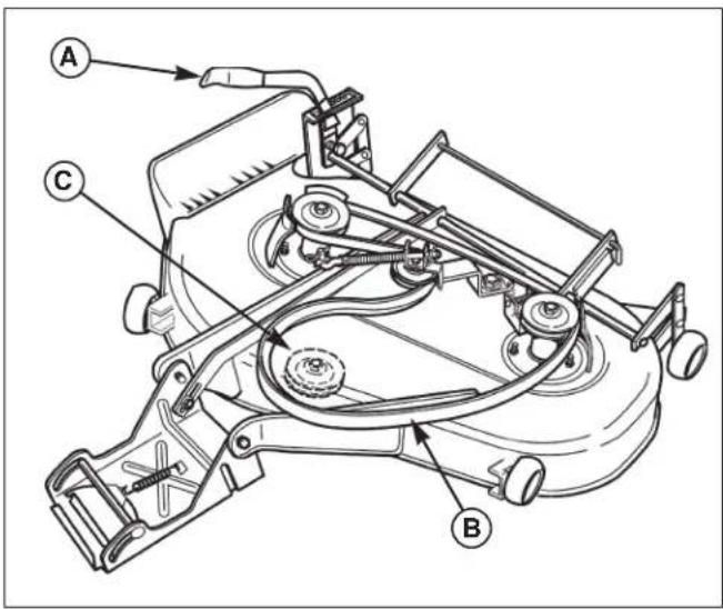
Figure 7. Mower Belt Routing
A. Mower Height Adjustment Lever C. Engine Pulley
B. Mower Drive Belt
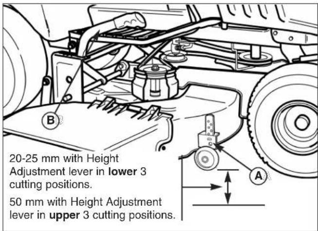
Figure 8. Mower Deck - Right Side
A. Pin and Clip B. Height Adjustment Lever
STORAGE
Temporary Storage (30 Days Or Less)
Remember, the fuel tank will still contain some gasoline, so never store the unit indoors or in any other area where fuel vapor could travel to any ignition source. Fuel vapor is also toxic if inhaled, so never store the unit in any structure used for human or animal habitation.
Here is a checklist of things to do when storing your unit temporarily or in between uses:
- Keep the unit in an area where children will not come into contact with it. If there's any chance of unauthorized use, remove the keys and disconnect the spark plug wires.
- If the unit can't be stored on a reasonably level surface, chock the wheels.
- Clean all grass and dirt from the mower.
Note: If storing your tractor between winter snow removal jobs in a cold area, we suggest that you fill the fuel tank at the completion of each job to prevent water condensation in the fuel tank. Wait for engine to cool before filling tank.
Long Term Storage (Longer Than 30 Days)
Before you store your unit for the off-season, read the Maintenance and Storage instructions in the Safety Rules section, then perform the following steps:
- Drain crankcase oil and refill with a grade of oil that will be required when unit is used again.
- Prepare the mower deck for storage as follows:
a. Remove mower deck from the unit.
b. Clean underside of mower deck.
c. Coat all bare metal surfaces with paint or light coat of oil to prevent rusting.
- Clean external surfaces and engine.
- Prepare engine for storage. See engine owner's manual.
- Clean any dirt or grass from cylinder head cooling fins, engine housing and air cleaner element.
- Cover air cleaner and exhaust outlet tightly with plastic or other waterproof material to keep out moisture, dirt and insects.
- Completely grease and oil unit as outlined in the Normal Care section.
- Clean up unit and apply paint or rust preventative to any areas where paint is chipped or damaged.
- Be sure the battery is fully charged. Battery life will be increased if it is removed, put in a cool, dry place and fully charged about once a month. If battery is left in unit, disconnect the negative cable.

WARNING

Never store the unit, with gasoline in engine or fuel tank, in a heated shelter or in enclosed, poorly ventilated enclosures. Gasoline fumes may reach an open flame, spark or pilot light (such as a furnace, water heater, clothes dryer, etc.) and cause an explosion.
Handle gasoline carefully. It is highly flammable and careless use could result in serious fire damage to your person or property.
Drain fuel into an approved container outdoors away from open flame or sparks.
- Drain fuel system completely or add a gasoline stabilizer to the fuel system. If you have chosen to use a fuel stabilizer and have not drained the fuel system, follow all safety instructions and storage precautions in this manual to prevent the possibility of fire from the ignition of gasoline fumes. Remember, gasoline fumes can travel to distant sources of ignition and ignite, causing risk of explosion and fire.
Note: Gasoline, if permitted to stand unused for extended periods (30 days or more), may develop gummy deposits which can adversely affect the engine carburetor and cause engine malfunction. To avoid this condition, add a gasoline stabilizer to the fuel tank and run the engine a few minutes, or drain all fuel from the unit before placing it in storage.
STARTING AFTER LONG TERM STORAGE
Before starting the unit after it has been stored for a long period of time, perform the following steps.
- Remove any blocks from under the unit.
- Install the battery if it was removed.
- Unplug the exhaust outlet and air cleaner.
- Fill the fuel tank with fresh gasoline. See engine manual for recommendations.
- See engine owner's manual and follow all instructions for preparing engine after storage.
- Check crankcase oil level and add proper oil if necessary. If any condensation has developed during storage, drain crankcase oil and refill.
- Inflate tires to proper pressure. Check fluid levels.
- Start the engine and let it run slowly. DO NOT run at high speed immediately after starting. Be sure to run engine only outdoors or in well ventilated area.
MAINTENANCE SCHEDULE & PROCEDURES
The following schedule should be followed for normal care of your tractor and mower.
| SAFETY ITEMS Each Use 5 Hours 25 Hours | Before 100 Hours | Every 250 Hours & Fall | Every Fall | Every Spring | |
| Check Safety Interlock System | |||||
| Check Tractor Brakes | |||||
| Check Mower Blade Stopping Time | ● | ||||
| NORMAL CARE ITEMS | Before Every Every Every Every Every Each Use Each 5 Hours 25 Hours Spring 100 Hours 250 Hours & Fall | ||||
| Check Tractor/Mower for loose hardware | ● | ||||
| Check Engine Oil Level | * ● | ***● | |||
| Check / Change Engine Air Filter | *, *** | ||||
| Change Engine Oil & Filter | *, ** | ||||
| Inspect Spark Plug(s) | * | ||||
| Check / Replace Fuel Filter | ● | ||||
| Clean / Replace Exhaust Screen | ‡ | ||||
| Check Transmission Oil Level | ● | ||||
| Lubricate Tractor & Mower | ***● | ||||
| Lubricate Rear Axle Shafts | |||||
| Clean Battery & Cables | ● | ||||
| Check Tire Pressure | ● | ||||
| Clean & Sharpen Mower Blades | ● | ||||
‡ Clean or replace exhaust screen every 50 hours.
* See the engine manufacturer's owner's manual.
** Change original engine oil after initial break-in period. Refer to engine owner's manual.
*** More often in hot (over 85° F: 30° C) weather or dusty operating conditions.
Always refer to the engine manufacturer's owner's manual for specific engine information.
RAISING THE HOOD & SEAT
To raise the hood, grasp the hood recess (Figure 9) on top, then pivot the hood up and forward.
To raise the seat for battery access, tilt the seat forward.

NOTICE
Do not run the tractor with the hood raised. Engine heat will damage the headlight bezel and hood.

WARNING

Gasoline is highly flammable and must be handled with care. Never fill the tank when the engine is still hot from recent operation. Do not allow open flame, smoking or matches in the area. Avoid over-filling and wipe up any spills.
Do not remove fuel filter when engine is hot, as spilled gasoline may ignite. DO NOT spread hose clamps further than necessary. Ensure clamps grip hoses firmly over filter after installation.

Do not use gasoline containing METHANOL, gasohol containing more than 10% ETHANOL, gasoline additives, or white gas because engine/fuel system damage could result.
CHECKING/ ADDING FUEL
To add fuel:
- Remove the cap from the fuel tank (A, Figure 10).
- Fill the tank. Do not overfill. Leave room in the tank for fuel expansion. Refer to your engine manual for specific fuel recommendations.
- Install and hand tighten the fuel cap.
CHECK TIRE PRESSURES
Service Interval: Every 25 Hours
Tire Pressure should be checked periodically, and maintained at the levels shown in the chart. Note that these pressures may differ slightly from the "Max Inflation" stamped on the side-wall of the tires. The pressures shown provide proper traction, improve cut quality, and extend tire life.
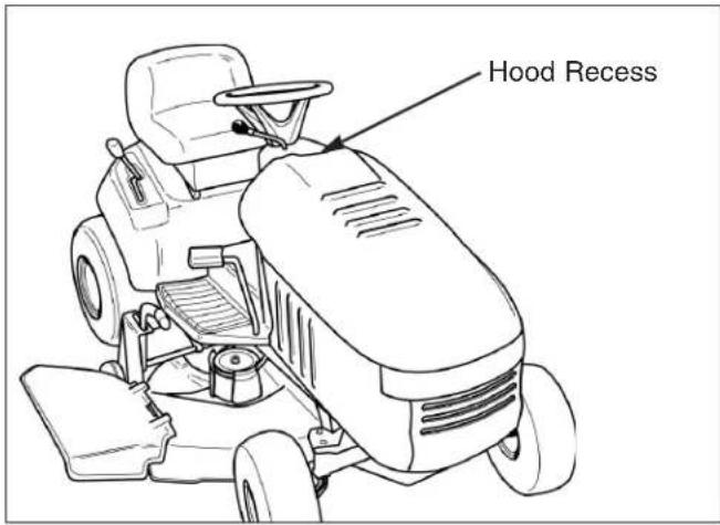
Figure 9. Gas Tank Located Under Hood
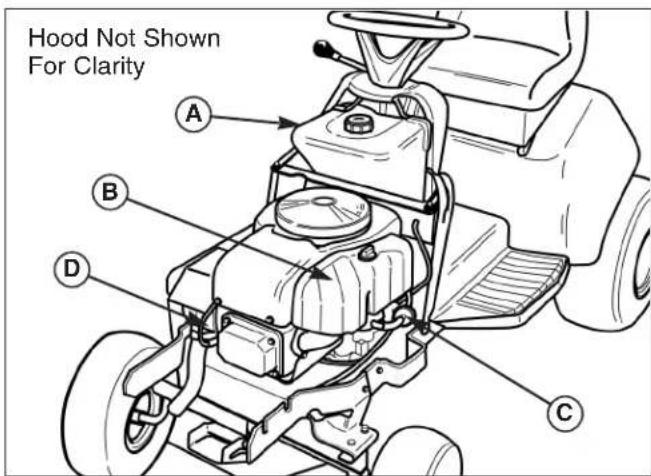
Figure 10. Engine Compartment
A. Gas Tank C. Fuel Filter
B. Air Filter D. Spark Plug
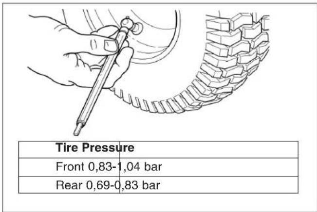
Figure 11. Checking Tire Pressure
CHECK/ REPLACE FUEL FILTER
Service Interval: Every 100 Hours
The fuel filter is located in the fuel line between the fuel tank and the carburetor (left side of engine).
If filter is dirty or clogged, replace as follows:
- Disengage the PTO, engage the parking brake, turn the ignition switch OFF, and remove the key. Allow the engine to cool. Disconnect the negative battery cable.
- Place a container below the filter to catch spilled fuel.
- Using a pliers, open and slide hose clamps from fuel filter.
- Remove hoses from filter.
- Install new filter in proper flow direction in fuel line.
- Secure with hose clamps.
- Reconnect the negative battery cable when finished.
ENGINE MAINTENANCE
The following engine maintenance procedures and service intervals can be found in your Engine Owner's Manual. Refer to Figure 12 for engine maintenance item locations.
• Engine Oil & Filter Check / Change
- Check / Change Air Filter
• Inspect & Replace Spark Plugs
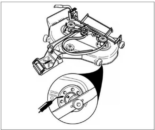
BLADE BRAKE CHECK
Service Interval: Every 100 Hours or Fall & Spring
Mower blades and mower drive belt should come to a complete stop within five seconds after PTO is disengaged.
- With tractor in neutral, PTO disengaged and operator in seat, start the engine.
- Engage the PTO and wait several seconds. Disengage the PTO and check the amount of time it takes for the mower drive belt to stop.
- If mower drive belt does not stop within five seconds, see your dealer.
SAFETY INTERLOCK SYSTEM CHECK
Service Interval: Every Fall & Spring
Check the function of the safety interlock system using the test procedure found on page 7 of this manual. If the tractor fails any of the tests, see your dealer.
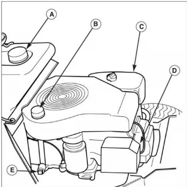
Figure 12. Engine Compartment
A. Gas Tank D. Spark Plug
B. Oil Fill/ Dip Stick E. Oil Drain
C. Air Filter

Figure 13. Mower Deck Clutch & Brake System
A. Non-Adjustable Pulley Brakes
HYDRO TRANSMISSION SERVICE

Do not allow dirt, water, or other debris to enter the expansion chamber or transmission. Even a small amount of dirt can damage the transmission
Transmission Service Information
Service Interval: Check Oil Level Every 250 Hrs
Transmission Oil Capacity: Approx. 2-1/2 Quarts
Transmission Oil Type: SAE 10W-30 with a minimum API rating of SG/CD.
The Tuff Torq K-51 hydrostatic drive transmission does not require regular maintenance other than checking the oil level every 250 hours. See your Authorized Dealer for transmission service.
Attention: It is critical that dirt and water be kept out of the transmission. Thoroughly clean and dry all the surrounding surfaces before opening the transmission.
- Tilt the seat forward to access the battery compartment (Figure 14)
- Remove the battery and clean the battery compartment. (See Battery Maintenance).
- Clean off the fill plug (see Figure 15) and surrounding area.
- Using a screwdriver, pry the fill plug out of the transmission and remove the spring.
- Check the oil level. The transmission should be filled with oil up to the top notch (see Figure 15 inset). If not, add oil.
- Replace the fill plug. Reinstall the battery. (See Battery Maintenance).
- Perform the transmission purging procedure found in the Service section.
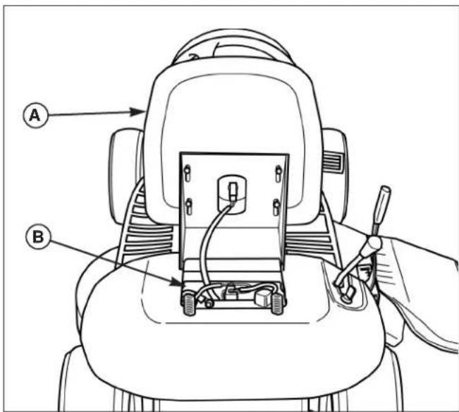
Figure 14. Seat Adjustment
A. Seat B. Battery Compartment
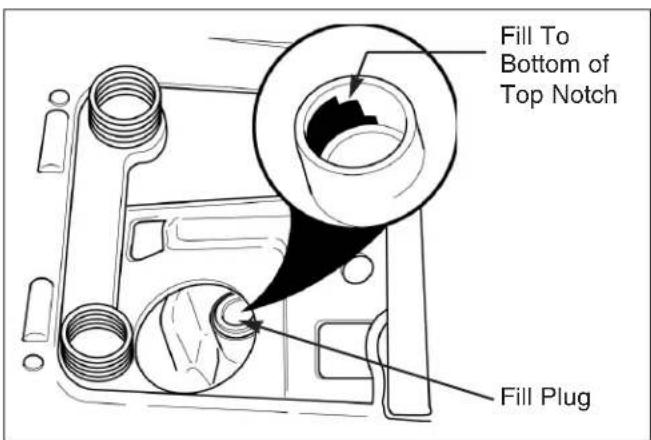
Figure 15. Hydro Transmission Fill Plug Location
EXHAUST SCREEN SERVICE

WARNING

Always allow the engine to cool before beginning any service work were the muffler or exhaust components must be handled. Wear gloves when handling exhaust components.
Service Interval: Every 50 Hours
Inspect, clean or replace the exhaust screen after every 50 hours of operation.
- Park the tractor on a level surface. Disengage the PTO, turn off the engine and set the parking brake. Remove the key. Allow the engine and muffler to cool.
- Remove the screw (B, Figure 16). Using a pair of pliers, remove the exhaust screen (A).
BATTERY INSTALLATION

WARNING

Be careful when handling the battery. Keep flames and sparks away from the battery.
When removing or installing battery cables, disconnect the negative cable FIRST and reconnect it LAST. If not done in this order, the positive terminal can be shorted to the frame by a tool.
The Battery is free of Maintenance
Connecting the Battery
See Figure 17. Connect the battery cables (positv cable first, B, Figure 17). Position the positive battery cable over seat switch harness to prevent harness from becoming pinched in seat pivot. Make sure that protective terminal cover (G) is in place over positive battery post as shown in Figure 17.
Recharging the Battery
Recharge the battery according to the manufacturer's instructions.
Cleaning the Battery and Cables
Service Interval: Every 100 Hours
- First, disconnect the negative battery cable (A) from the battery terminal (E). Second, disconnect the positive battery cable (B) from the battery terminal (F).
- Remove the battery from the battery compartment.
- Clean the battery compartment with a solution of baking soda and water.

Figure 16. Clean / Replace Exhaust Screen
A. Exhaust Screen B. Screw
- Inspect the screen. Shake any particles from the screen. If necessary, clean the screen with a wire brush and safety solvent. Reinstall the screen or if it is excessively dirty or damaged, replace it.
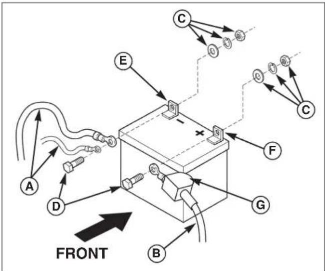
Figure 17. Battery Cables & Fill
A. Negative Cable C. Nut, Lockwasher, & Washer B. Positive Cable & Cover D. Capscrew
- Clean the battery terminals (E and F) and cable ends with a wire brush and battery terminal cleaner until shiny.
- Reinstall the battery in the battery compartment.
- First, reconnect the positive battery cable (B) to the positive battery terminal (F). Slide the terminal cover (G) into place. Second, reconnect the negative battery cable (A) to the negative battery terminal (E).
- Coat the cable ends and battery terminals with petroleum jelly or non-conducting grease.
LUBRICATION
Service Interval: Every 25 Hours
Lubricate the unit at the locations shown in Figures 18 through 21 as well as the following lubrication points.
Grease:

- front axle pivot
- front wheel bearings
- steering linkage
- foot pedal
- mower pivots
- mower arbors
• transmission idler assembly pivot - rear axle shafts (remove wheels)
Use grease fittings when present. Disassemble parts to apply grease to moving parts when grease fittings are not present.
Not all greases are compatible. Automotive-type lithium grease may be used.
Oil:

- hydro linkage
- brake linkage
- frame pivot points
- mower deck height adjustment linkage
Generally, all moving metal parts should be oiled where contact is made with other parts. Keep oil and grease off belts and pulleys. Remember to wipe fittings and surfaces clean both before and after lubrication.
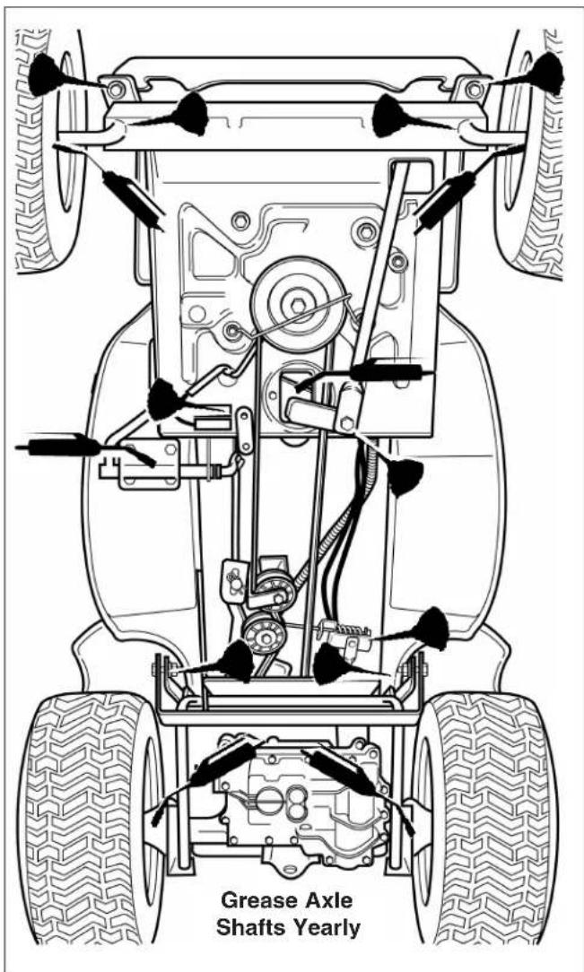
Figure 18. Lubricating Tractor - Typical
natural_image
Technical line drawing of a mechanical device with an inset close-up showing a circular component detail (no text or symbols)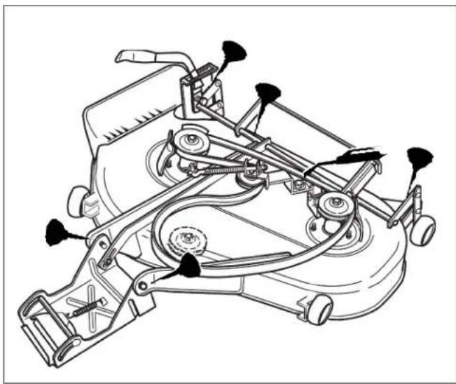
natural_image
Technical line drawing of a mechanical device with multiple arms and levers (no text or symbols)Figure 20. Arbor Lubrication Points Figure 21. Lubricate Deck Linkage
LUBRICATE REAR AXLE SHAFTS
Service Interval: Yearly
We recommend removing the rear wheels and lubricating the axle shafts yearly. This prevents the wheel from seizing onto the axle shaft and makes future service easier.
- Remove the key and disconnect the spark plug wire while working on the unit.
- Engage the parking brake and block the front wheels.
- Using a jack or chain hoist positioned at the center of the rear frame, carefully jack the unit up until the rear tires are approximately 2,5 cm - 5 cm off the ground.
Note: For overall unit stability during service, do not jack rear end higher than required for wheel removal.
- Support the rear of the unit on jackstands positioned under the rear frame.
- Remove the plastic hub cap (G, Figure 22).
- Remove e-ring (F) using a screwdriver.
- Remove the large washer (B), small washer (E), and wheel assembly (D).
- Lubricate the axle shaft with anti-seize compound or lithium grease.
- Reinstall components in reverse order of disassembly and lower the unit.
Note: Gear drive models also have grease fittings located in the transmission casing beneath the axle bearings. Lubricate the grease fittings once a year.

WARNING

Always use a properly working lifting device with a capacity suitable for the weight of the unit being serviced.
Always use a jack stand to support the unit while performing service, and chock remaining wheels to prevent the unit from rolling off the supports.
Never work under or around an elevated unit that is not properly supported and secured in position with wheel chocks.
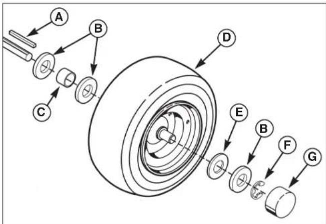
Figure 22. Lubricate the Rear Axle Shafts
A. Key E. Small Washer (As Required)
B. Large Washers F. E-Ring
C. Spacer G. Hub Cap
D. Wheel Assembly.
SERVICING THE MOWER BLADES

WARNING

For your personal safety, do not handle the sharp mower blades with bare hands. Careless or improper handling of blades may result in serious injury.
Service Interval: Every 100 Hours or As Required
- Remove mower from the tractor. See Mower Installation & Removal.
- Blades should be sharp and free of nicks and dents. If not, sharpen blades as described in following steps.
- To remove blade for sharpening, use a wood block to hold blade while removing the blade mounting capscrew (Figure 23).
- Use a file to sharpen blade to a fine edge. Remove all nicks and dents in the blade edge. If the blade is severely damaged, it should be replaced.
- Balance the blade as shown in Figure 24. Center the blade's hole on a nail lubricated with a drop of oil. A balanced blade will remain level.
- Reinstall each blade with the tabs pointing up toward deck as shown in Figure 25. Secure with a capscrew, spring washer and hex washer (be certain the hex washer is aligned with the hex shaft). Use a wooden block to prevent blade rotation and torque capscrews to 61-75 N.m.

WARNING

For your personal safety, blade mounting capscrews must each be installed with a hex washer and spring washer, then securely tightened. Torque blade mounting capscrew to 61 - 75 N.m.
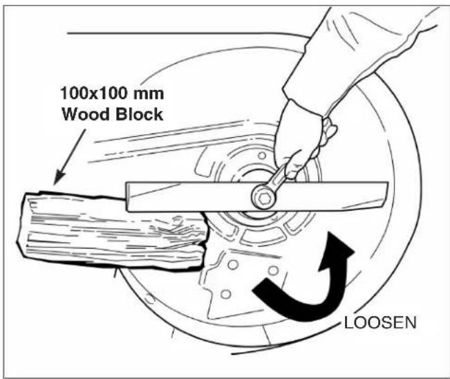
Figure 23. Removing the Blade
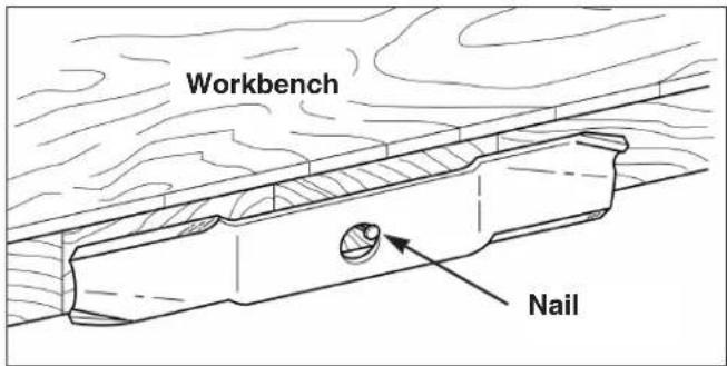
Figure 24. Balancing The Blade
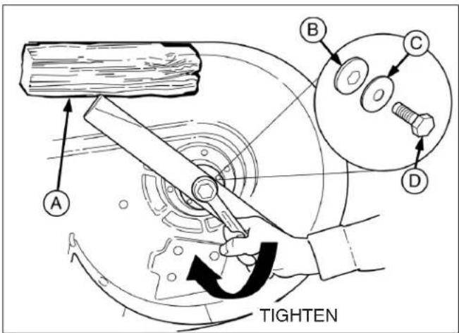
Figure 25. Installing The Blade
A. 100x100 mm Wood Block C. Spring Washer
B. Hex Washer D. Blade Bolt
COMMON REPLACEMENT PARTS
Listed below are the more common replacement parts. Only genuine factory replacement parts will assure optimum performance and safety. Do not attempt repairs or maintenance unless proper procedures and safety precautions are followed. For assistance in any area, see your dealer.
Replacement Parts
38" Mower
QTY. DESCRIPTION PART NO.
1 Mower Blades, R.H. 6152 702 0110
1 Mower Blades, L.H. 6152 702 0100
While normal care and regular maintenance will extend the life of your equipment, prolonged or constant use may eventually require that service be performed to allow it to continue operating properly.
The troubleshooting guide below lists the most common problems, their causes and remedies.
See the information on the following pages for instructions on how to perform most of these minor adjustments and service repairs yourself. If you prefer, all of these procedures can be performed for you by your local authorized dealer.

WARNING

To avoid serious injury, perform maintenance on the tractor or mower only when the engine is stopped and the parking brake engaged.
Always remove the ignition key, disconnect the spark plug wire and fasten it away from the plug before beginning the maintenance, to prevent accidental starting of the engine.
TROUBLESHOOTING THE TRACTOR
| SYMPTOM PROBLEM | SOLUTION | |
| Engine will not turnover or start. | 1. Ground speed lever not in neutral-start position.2. PTO lever in ON position.3. Out of fuel.4. Engine flooded.5. Circuit breaker tripped.6. Battery terminals require cleaning.7. Battery discharged or dead.8. Wiring loose or broken.9. Solenoid or starter motor faulty.10. Safety interlock switch faulty.11. Spark plug(s) faulty, fouled.12. Water in fuel.13. Fuel is old or stale.14. Clutch/Brake pedal not depressed. | 1. Shift into neutral.2. Place in OFF position.3. If engine is hot, allow it to cool, then refill the fuel tank.4. Move throttle control out of CHOKE position.5. Wait one minute for automatic reset, replace if defective.6. See Maintenance Section.7. Recharge or replace.8. Visually check wiring & replace if damaged. Tighten loose connections.9. Repair or replace. See authorized dealer.10. See authorized service dealer.11. See engine manual.12. Drain fuel & refill with fresh fuel.13. Drain fuel & replace with fresh fuel.14. Depress pedal. |
| Engine starts hard or runs poorly. | 1. Fuel mixture too rich.2. Spark plug faulty, fouled, or incorrectly gapped. | 1 Clean air filter. Check choke adjustment (engine speed control).2. See engine manual. |
| Engine knocks. | 1. Low oil level.2. Using wrong grade oil. | 1. Check/add oil as required.2. See engine manual. |
| Excessive oil consumption. | 1. Engine running too hot.2. Using wrong weight oil.3. Too much oil in crankcase. | 1. Clean engine fins, blower screen and air cleaner.2. See engine manual.3. Drain excess oil. |
| Engine exhaust is black. | 1. Dirty air filter.2. Engine throttle control is in choke position. | 1. Replace air filter. See maintenance section.2. Change engine speed control position. |
| Engine runs, but tractor will not drive. | 1. Ground speed lever in neutral.2. Transmission release lever in “push” position.3. Belt is broken.4. Drive belt slips.5. Brake is not fully released. | 1. Shift in forward or reverse.2. Move into drive position.3. See Drive Belt Replacement.4. See problem and cause below.5. See authorized service dealer |
TROUBLESHOOTING THE TRACTOR - CONTINUED
SYMPTOM PROBLEM SOLUTION
| Tractor drive belt slips. | 1. Clutch is out of adjustment.2. Pulleys or belt greasy or oily.3. Belt stretched or worn.4. Idler pulley pivot bracket “frozen” in de-clutched position. | 1. See authorized service dealer.2. Clean as required.3. Replace belt.4. Remove idler pulley bracket, clean and lubricate. |
| Brake will not hold. | 1. Brake is incorrectly adjusted.2. Internal brake disc on transaxle worn. | 1. See Brake Adjustment.2. See authorized service dealer transaxle worn. |
| Tractor steers hard or handles poorly. | 1. Steering linkage is loose.2. Improper tire inflation.3. Spindle bearings dry. | 1. Check and tighten any loose connections. See Steering Gear Adjustment.2. See Maintenance Section.3. Grease spindles. See Lubrication Section. |
| Drive belt does not stop when clutch/brake pedal depressed. | 1. Belt stops or belt tension out of adjustment. | 1. See authorized service dealer. |
TROUBLESHOOTING THE MOWER
SYMPTOM PROBLEM SOLUTION
| Mower cut is uneven. | 1. Mower not leveled properly.2. Tractor tires not inflated equally or properly. | 1. See Mower Adjustment.2. See Maintenance Section. |
| Mower cut is rough looking. | 1. Engine speed too slow.2. Ground speed too fast.3. Blades are dull.4. Mower drive belt slipping because it is oily or worn.5. Mower drive belt slipping because PTO clutch is out of adjustment.6. Blades not properly fastened to arbors. | 1. Set to full throttle.2. Slow down.3. Sharpen or replace blades. See Mower Blade Service.4. Clean or replace belt as necessary.5. See PTO Clutch Adjustment.6. See Servicing the Mower Blades. |
| Engine stalls easily with mower engaged. | 1. Engine speed too slow.2. Ground speed too fast.3. Cutting height set too low.4. Discharge chute jamming with cut gras. | 1. Set to full throttle.2. Slow down.3. Cut tall grass at maximum cutting height during first pass.4. Cut grass with discharge pointing toward previously cut area. |
| Excessive mower vibration. | 1. Blade mounting screws are loose.2. Mower blades, arbors, or pulleys are bent.3. Mower blades are out of balance.4. Belt installed incorrectly.5. PTO Clutch out of adjustment. | 1. Tighten to 61-75 N.m.2. Check and replace as necessary.3. Remove, sharpen, and balance blades. See Maintenance Section.4. Reinstall Correctly.5. See PTO Clutch Adjustment. |
| Excessive belt wear or breakage. | 1. Bent or rough pulleys.2. Using incorrect belt.3. PTO Clutch out of adjustment. | 1. Repair or replace.2. Replace with correct belt.3. See PTO Clutch Adjustment. |
| Mower drive belt slips or fails to drive. | 1. Idler pulley or arbor bearing seized.2. Mower drive belt broken.3. PTO Clutch out of adjustment. | 1. Repair or replace as needed.2. Replace drive belt.3. See PTO Clutch Adjustment. |
Troubleshooting, Adjustment, & Service

WARNING

Engage parking brake, disengage PTO, stop engine, disconnect spark plug wire(s), and remove key before performing service.
SEAT ADJUSTMENT
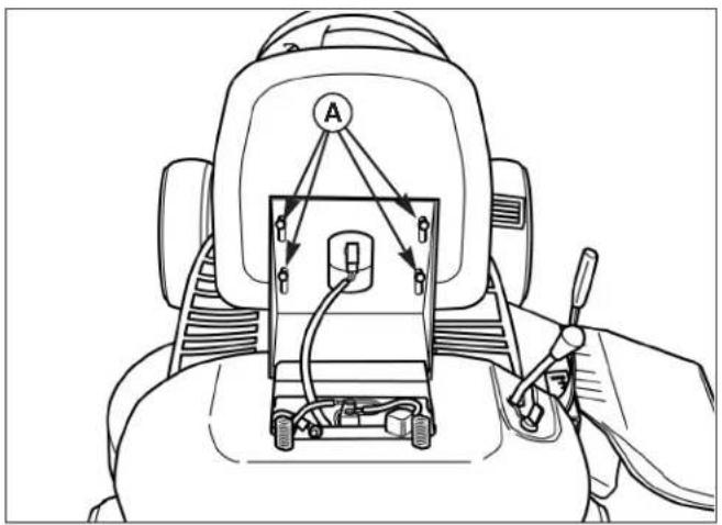
The seat can be adjusted forward and back. Loosen the four seat adjustment capscrews (A, Figure 26), slide the seat to the desired position, and tighten the capscrews.
natural_image
Line drawing of a robotic arm holding a small electronic device with labeled components (no text or symbols present)Figure 26. Seat Adjustment
A. Capscrews
STEERING GEAR ADJUSTMENT
If there is excessive slack in the steering system, the steering gear backlash can be removed.
- See Figure 27. Loosen the two nuts and adjust the bracket so the gear teeth are closely meshed.
- Tighten nuts after adjustment.
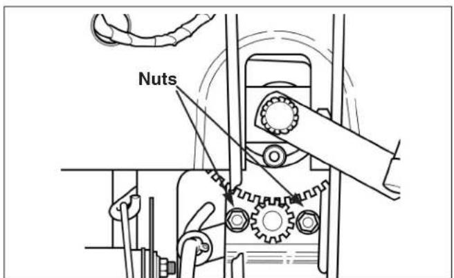
Figure 27. Steering Gear Adjustment
Note: All hydro brake adjustment is accomplished through brake spring adjustment.
- Fully depress brake pedal and lock parking brake.
- See Figure 28. With the tractor parked on a level surface adjust the brake rod nut (A) until spring (B) is compressed to a length of 43 mm to 45 mm.
- Check the adjustment by backing the tractor up a hill, engaging the parking brake, and shutting off the engine. While seated in the operator's position park the tractor for at least 30 seconds and watch for movement.
If the parking brake does not hold, tighten the spring. If the parking brake cannot be engaged, loosen the brake spring.
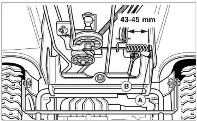
Figure 28. Brake Spring Adjustment - Hydro Models
A. Nut B.
MOWER ADJUSTMENTS
PTO Clutch Adjustment
The PTO clutch adjustment should be checked whenever clutch parts are replaced, when a new belt is installed, or if the mower belt is slipping.
- Disengage the PTO lever. Set the mower height adjustment lever to mid-cut position.
- Loosen the set collar (B, Figure 29).
-
Pull the clutch rod back until the cotter pin and washer (C) contacts the U-shaped bracket (D). Slide the set collar (B) forward to remove all slack from the clutch rod and spring assembly. The collar should be touching the spring, but not compressing it.
-
Tighten the set collar (B).
Note: The set screw should face the rear of the unit.
-
Engage the PTO lever.
-
Measure the length of the compressed clutch spring (A). The spring should be 73 mm to 76 mm when compressed.
-
Check the mower blade stopping time. The blades should stop within 5 seconds. If the blades do not stop within 5 seconds contact your authorized dealer.
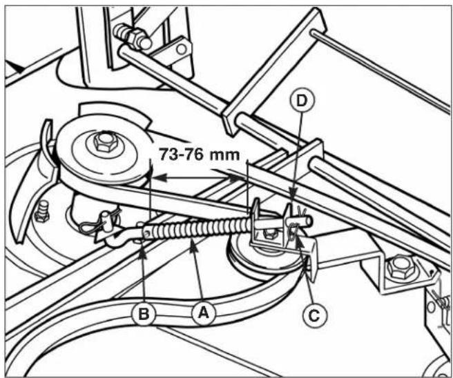
Figure 29. PTO Clutch Adjustment
A. Clutch Spring C. Cotter Pin
B. Set Collar D. U-Shaped Bracket
Troubleshooting, Adjustment, & Service

WARNING

Before checking mower, shut off engine and disengage PTO. Allow all moving parts to stop. Remove ignition key, then disconnect the spark plug wire and fasten it away from the spark plug.
Leveling The Mower
If the cut is uneven, the mower may need leveling. Unequal or improper tire pressure may also cause an uneven cut. Tire pressure should be as follows:
- Front: 0,83-1,04 bar
- Rear: 0,69-0,83 bar
SIDE-TO-SIDE ADJUSTMENT
- With the mower installed, place the tractor on a smooth, level surface such as a concrete floor. Turn the front wheels straight forward.
- Check for bent blades and replace if necessary.
- Place the mower in high-cut position. Arrange the mower blades so that they are pointing from side-to-side (Figure 30).
- See Figure 32. Measure the distance between the outside tips of the outer blades and the ground. If there is more than 3 mm difference between the measurements on each side, proceed to step 5. If the difference is 3 mm or less, proceed to Front-to-Back Leveling.
- See Figure 31. Loosen the outside nut (A) and taptite screw (C), then turn the eccentric nut (B) to raise or lower the left side of the deck. When the mower deck is level, hold the eccentric nut while tightening the outside nut. Tighten the taptite screw (C).
natural_image
Technical line drawing of a mechanical component with two circular parts and directional arrows indicating movement (no text or symbols)Figure 30. Orient Blades Side-to-Side
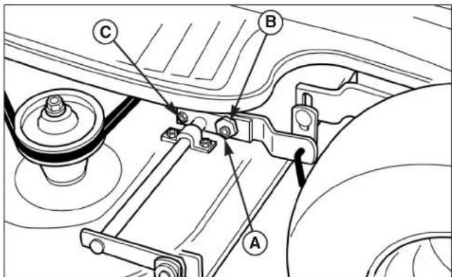
Figure 31. Side-to-Side Adjustment
A. Outside Nut C. Taptite Screw
B. Eccentric Nut
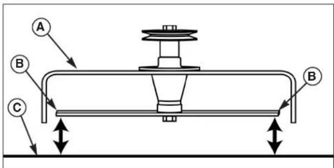
Figure 32. Measure Blade Tips to Ground
A. Mower Deck C. Level Ground
B. Blade Tips
FRONT-TO-BACK ADJUSTMENT
- Arrange the blades so they face front-to-back (Figure 33).
- See Figure 32. Measure the distance from the ground to the front and rear tips of the blades as shown. Front tips should be equal to rear tips or within 3 mm higher. If not, proceed to step 3.
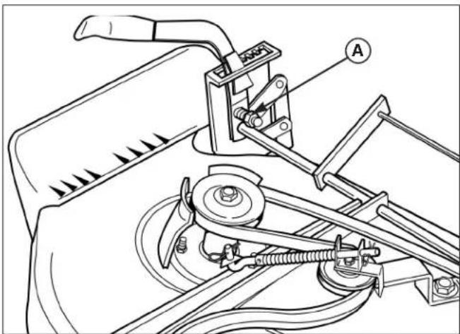
- See Figure 34. Loosen the outside nut (A) and turn the eccentric nut (B) to raise or lower the rear of the deck. When the mower deck is level, hold the eccentric (B) while tightening the outside nut (A).
Note: If mower handle drops out of cutting height quadrant, turn adjustment nut (A, Figure 35) clockwise to increase spring tension. DO NOT tighten nut all the way so that the spring is solid.
Blade Brake Check
Mower blades and mower drive belt should come to a complete stop within five seconds after the PTO lever is disengaged.
- With tractor in neutral, PTO disengaged and operator in seat, start the engine.
- Engage the PTO and wait several seconds. Disengage the PTO and check the amount of time it takes for the mower drive belt to stop.
- If mower drive belt does not stop within five seconds, see your dealer.
natural_image
Technical line drawing of a mechanical component with mounting holes and internal features (no text or symbols)Figure 33. Orient Blades Front-to-Back
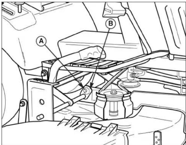
Figure 34. Front-to-Back Adjustment Nut A. Nut B. Eccentric
natural_image
Technical line drawing of a mechanical assembly with labeled component A (no text or symbols beyond label)Figure 35. Handle Tension Adjustment
A. Adjustment Nut
Troubleshooting, Adjustment, & Service
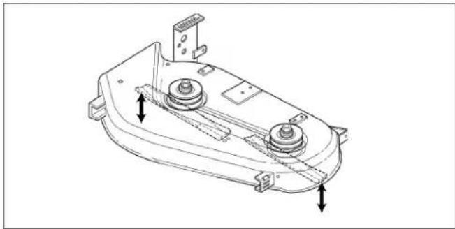
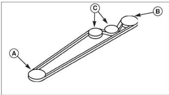
MOWER BELT REPLACEMENT
- Park the tractor on a level surface. Disengage the PTO, turn off the engine and set the parking brake. Remove the key.
- Remove the mower deck from the tractor. See Mower Installation & Removal.
- Loosen the nuts securing the belt guides (A, Figure 36).
- Note the position of the idler pulley belt guide (B). Loosen the idler pulley capscrew.
- Remove the old belt from the pulleys and install the new belt as shown in Figure 36.
- Tighten the belt guide nuts.
- Return the idler pulley belt guide (B) to its original position and tighten the idler pulley capscrew.
- Reinstall the mower deck on the tractor.
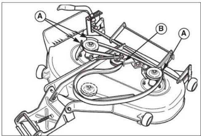
Figure 36. Mower Deck Belt Routing
A. Belt Guides C. Idler Pulley Capscrew
B. Idler Pulley Belt Guide
TRACTOR DRIVE BELT REPLACEMENT

To avoid damaging belts, DO NOT PRY BELTS OVER PULLEYS.
-
Park the tractor on a level surface. Disengage the PTO, turn off the engine and set the parking brake. Remove the key.
-
Remove the mower deck from the tractor. See Mower Installation & Removal.
-
Loosen the bolts securing the engine pulley belt guide (A, Figure 39).
-
Remove the rear drag link hardware (B, Figure 39). When reassembling, apply thread locking compound to nut before tightening.
-
Loosen the belt stop on the transmission pulley. Belt stop hardware is located on the inside of RH frame. Move belt stop out of the way. Belt stop should be positioned 3 mm from belt when new belt is installed and hardware is tightened.
-
Note the position of the idler pulley belt guide. Loosen hardware securing the idler pulleys (C, Figure 39).
-
Carefully slide belt over transmission pulley and remove from the idler pulleys (C, Figure 39).
-
Install new belt as shown in Figure 38.
-
Return the idler pulley belt guide to its original position and tighten the idler pulley hardware.
-
Reverse steps 1-5.
flowchart
graph TD
    A["A"] --> B["B"]
    B --> C["C"]
    C --> A
Figure 38. Drive Belt Routing - All Models
A. Engine Pulley C. Idler Pulleys
B. Transmission Pulley
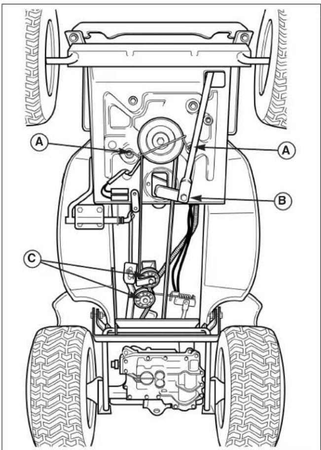
Figure 39. Drive Belt Replacement
A. Belt Stop Bolts C. Idler Pulleys B. Drag Link Hardware
BATTERY SERVICE

WARNING

Keep open flames and sparks away from the battery; the gasses coming from it are highly explosive. Ventilate the battery well during charging.
Checking Battery Voltage
A voltmeter can be used to determine condition of battery. When engine is off, the voltmeter shows battery voltage, which should be 12 volts. When engine is running, the voltmeter shows voltage of charging circuit which normally is 13 to 14 volts.
A dead battery or one too weak to start the engine may not mean the battery needs to be replaced. For example, it may mean that the alternator is not charging the battery properly. If there is any doubt about the cause of the problem, see your dealer. If you need to replace the battery, follow the steps under Cleaning the Battery & Cables in the Regular Maintenance Section.

WARNING

Do not attempt to charge a frozen battery. Allow the battery to warm to 60^ F ( 15.5^ C) before placing on charger.
Charging a Completely Discharged Battery
- Be aware of all the safety precautions you should observe during the charging operation. If you are unfamiliar with the use of a battery charger, have the battery serviced by your dealer.
- Always unplug or turn the charger off before attaching or removing the clamp connections.
- Carefully attach the clamps to the battery in proper polarity (usually red to [+] positive and black to [-] negative).
- Charge the battery until fully charged.
Jump Starting With an Auxiliary (Booster) Battery
Jump starting is not recommended. However, if it must be done, follow these directions. Both booster and discharged batteries should be treated carefully when using jumper cables. Follow the steps below EXACTLY, being careful not to cause sparks. Refer to Figure 40.
- Both batteries must be of the same voltage.
- Position the vehicle with the booster battery adjacent to the vehicle with the discharged battery so that booster cables can be connected easily to the batteries in both vehicles. Make certain vehicles do not touch each other.
- Wear safety glasses and shield eyes and face from batteries at all times.
- Connect positive (+) cable to positive post of discharged battery (wired to starter or solenoid).
- Connect the other end of same cable to same post marked positive (+) on booster battery.
- Connect the second cable negative (-) to other post of booster battery.
- Make final connection on engine block of stalled vehicle away from battery. Do not lean over batteries.
- Start the engine of the vehicle with the booster battery. Wait a few minutes, then attempt to start the engine of the vehicle with the discharged battery.
- If the vehicle does not start after cranking for thirty seconds, STOP PROCEDURE. More than thirty seconds seldom starts the engine unless some mechanical adjustment is made.
- After starting, allow the engine to return to idle speed. Remove the cable connection at the engine or frame. Then remove the other end of the same cable from the booster battery.
- Remove the other cable by disconnecting at the discharged battery first and then disconnect the opposite end from the booster battery.
THIS HOOK-UP FOR NEGATIVE GROUND VEHICLES
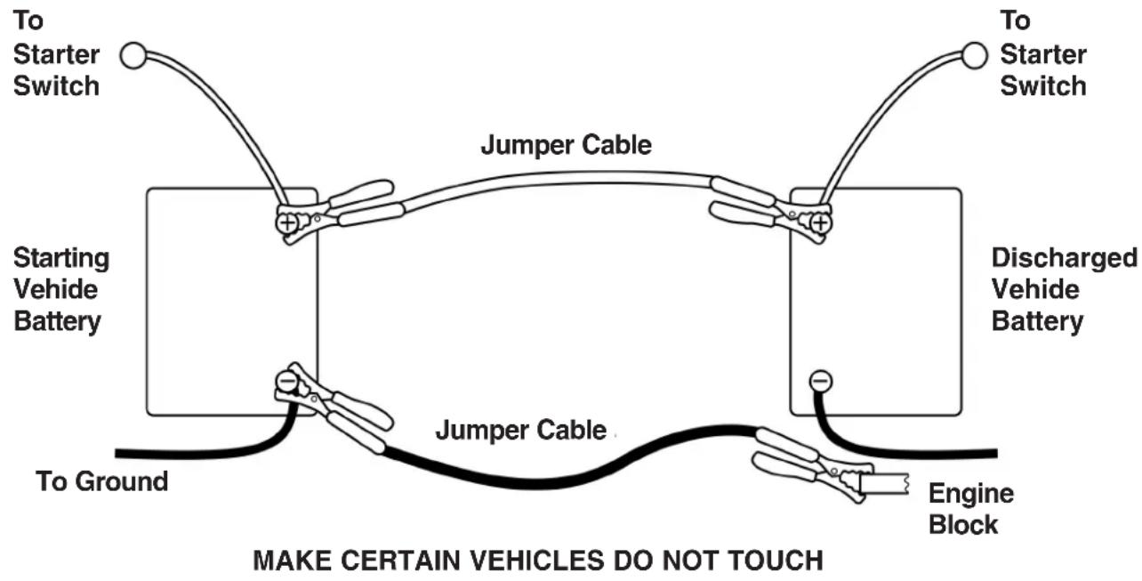
Figure 40. Battery Jump Starting Diagram

WARNING

Any procedure other than the preceding could result in:
(1) personal injury or property damage due to battery explosion,
(2) damage to the charging system of the booster vehicle or of the immobilized vehicle.
Do not attempt to jump start and start with jumper cables a vehicle having a frozen battery because the battery may rupture or explode.

WARNING

For your personal safety, use extreme care when jump starting. Never expose battery to open flame or electric spark.
When removing or installing battery cables, disconnect the negative cable FIRST and reconnect it LAST. If not done in this order, the positive terminal can be shorted to the frame by a tool.
To avoid engine damage, do not disconnect battery while engine is running. Be sure terminal connections are tight before starting.
Troubleshooting, Adjustment, & Service
TRANSMISSION PURGING
The following procedure applies to the Tuff Torq K-51 hydrostatic transaxle. Purge the transmission if the unit lacks drive in forward or reverse, or after an oil change
-
See Figure 41. Block the front wheels. Elevate the rear end of the tractor using a chain hoist or floor jack. Support the rear of the unit using jackstands. Elevate the unit just high enough for the rear wheels to clear the ground.
-
Activate the seat switch (A, Figure 41), depress the clutch / brake pedal (B, Figure 42), and start the engine. After the engine has started, set throttle (A) to IDLE.
-
Release the brake pedal (B) and move the ground speed lever (C) fully forward.
-
While holding the ground speed control in forward position, engage and disengage the transmission release valve lever (Figure 43) several times.
-
Move the ground speed lever (C, Figure 42) to full reverse.
-
While holding the ground speed control in reverse, engage and disengage the transmission release valve lever (Figure 43) several times.
-
Engage the transmission release valve lever (Figure 43) and move the ground speed lever (C, Figure 42) from full forward to full reverse several times.
-
Lower the tractor and test run for several minutes
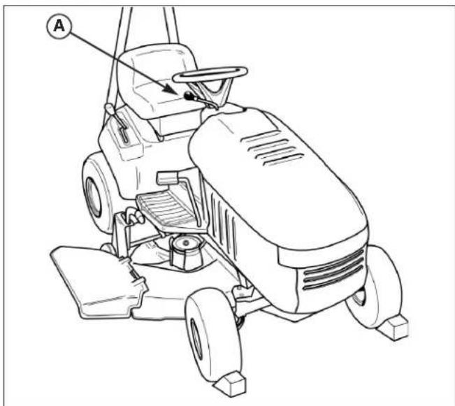
natural_image
Line drawing of a grass lawn mower with labeled component (A), no text or symbols presentFigure 41. Elevate the Rear End of the Tractor A. Seat Switch
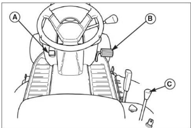
Figure 42. Controls
A. Throttle C. Ground Speed Lever B. Brake Pedal
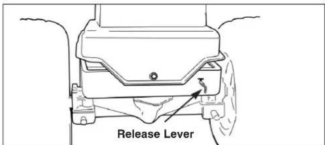
Figure 43. Release Lever
Note: Specifications are correct at time of printing and are subject to change without notice.
ENGINE
Engine, construction 4-stroke Briggs & Stratton internal combusting motor
Model 28S707 Intek 14,5 HP
Cylinder 1
Displacement 465 ccm
Performance 9,7 kW
Torque 25,7 Nm
Ignition High Energy Electronic Ignition
Electrical System 12 Volt, 3 amp Alternator Unregulated
Battery 200 Cold Cranking amps,
23 Minute Reserve Capacity
Speed of rotation
during the test 2500 rpm
TRANSMISSION
Type Hydrostatic Tuff Torq K51 HC
Pump Variable Displacement Axial Piston
Motor Fixed Displacement Axial Piston
Control Single Lever Hand Control
Movement Free-Wheeling Lever for Manual Tractor
Hydraulic Fluid 10w 30 Premium Engine Oil
Speeds Forward: 0 - 5,5 km/h
Reverse: 0 - 3,0 km/h
CHASSIS
Frame Heavy Gauge Steel Channel
Engine Mounting: Above Front Axle
Pivot Point Location: Rear Carrier
Rear Wheels Tire Size: 18 x 8.50-8 Carlisle
Pneumatic Inflation Pressure:
0,69 - 0,83 bar
Front Wheels Tire Size: 15 x 6.60-6 Carlisle
Pneumatic Inflation Pressure:
0,83 - 1,04 bar
Bearings: Sintered Iron with Grease Fittings
Accessibility Hood Tips Forward, Seat Tips Forward
Fuel Tank Material: High Density Polyethylene,
Transparent
Capacity: 7,5 L
Fuel Normal unleaded
Seat Medium Back, Adjustable
Turning Radius Inside Rear Tire: 36 cm
Sound power level
(EN 84/538/EEC) 100 dB(A)
Sound pressure level
(EN 79/113/EEC) 87 dB(A) (Measured at operator's position)
Vibration Data
at the steering wheel
(EN 1032, EN 1033)
Vibration Data
at the seat
(EN 1032, EN 1033) 0.4m / s^2 (Test performed on a concret floor)
CONTROLS
Steering 38 cm Steering Wheel
Gear and Sector, 1.5 turns Lock to Lock
Clutch/ Brake Combination Clutch/Brake/Parking Brake
Pedal. Parking Brake Lock,
Foot/Hand Activated
Location Mower Height Adjustment: Right Side
PTO Clutch-Manual: Dash Panel
Ground Speed Lever: Seat Deck R.H.
Ignition Key Switch: On Seat Deck
Throttle Lever & Choke Lever:
(Combined) On Dash Panel
DIMENSIONS
Tractor
Overall Length 172 cm
Overall Width 126 cm (with Deflector)
Height At Steering Wheel: 104 cm To Top of Engine Cover: 86 cm
Wheel Base 127 cm
Weight net 217 kg
38" Mower
Effective Cutting
Width 97 cm
Cutting Height Variable between 2,5 and 9,8 cm
Weight 55 kg
Blade Arrangement Two Blades
Mower Drive V-Belt from Tractor Engine Pulley
Spindle Bearings Sealed Ball Bearings - Lube Fitting Provided
Front wheels 2 adjust. gauge wheels
Rear wheels 3 settled gauge wheels
Common International Symbols
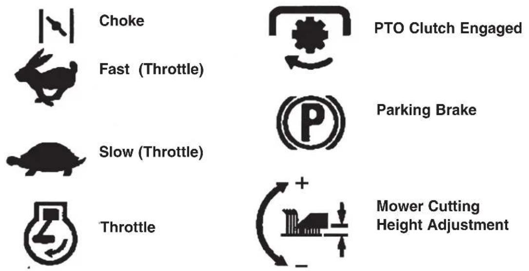
Choke
Fast (Throttle)
PTO Clutch Engaged
Parking Brake
Slow (Throttle)
Throttle
Mower Cutting Height Adjustment
English
Certificate of conformity
(Clause 8 of Directive 89/392/EEC)
I, the undersigned
Münchner Straße 17–21
A-6330 Kufstein
certify that the new machine
described below
Category: Lawn tractor
Rotary Mower
VIKING
Make:
Model: MT 820
Serialidentification: 6152
conform to the specifications of
Directives 98/37/EEC, 84/538/EEC
and 89/336/EEC.
Cutting Width [cm]: 97
Blade RPM [rpm]: 2200/ 2940
Gauranteed sound
power level LwA [dB(A)]: 100
The product has been developed and manufactured in compliance with the
following standard:
EN 836, EN 1032 and EN 1033
Done at Kufstein
on January 5th, 2000
Lechner
Vice president
Marketing
natural_image
Line drawing of a tractor-like vehicle with wheels and steering wheel (no text or symbols on the diagram itself)KENNUMMERN
Aufkleber - Gefahr.
Achtung:
natural_image
Line drawing of a chair with four legs and two side feet, showing seat structure and directional arrows (no text or symbols)Zusammenbau
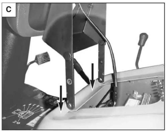
natural_image
Mechanical assembly diagram showing a lever mechanism with arrows indicating motion or force (no text or symbols present)
ANBAU DER RÄDER
Hinterräder
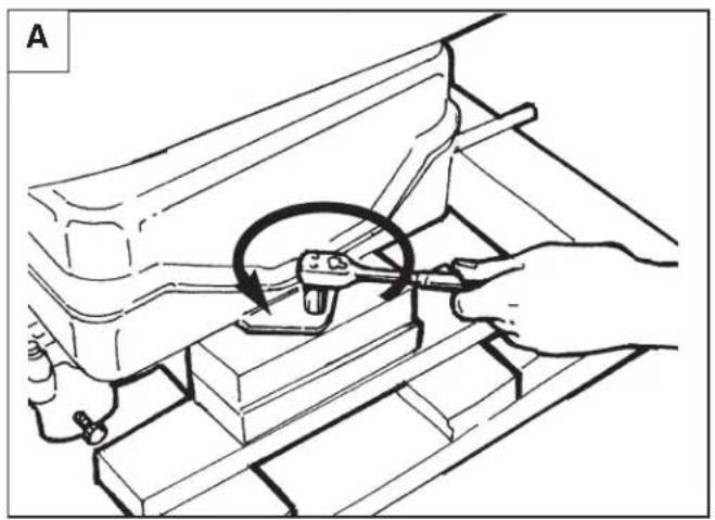
natural_image
Line drawing of hands using a tool to adjust or install a mechanical component, no text or symbols present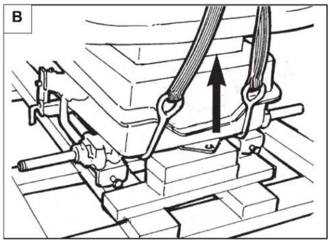
natural_image
Mechanical assembly diagram showing a lever mechanism with a directional arrow (no text or labels)
natural_image
Technical diagram of a mechanical assembly with no visible text or symbols
natural_image
Mechanical assembly diagram showing a shaft and housing with a directional arrow indicating motion (no text or symbols)
natural_image
Exploded view diagram of a mechanical assembly showing components like gears and shafts (no text or labels)
natural_image
Diagram showing concentric circular wave patterns with an arrow pointing to a small object (no text or symbols)
natural_image
Collection of mechanical washers and washers in various orientations (no text or labels)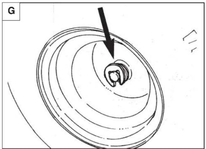
natural_image
Diagram of concentric circular patterns with a black arrow pointing to a small oval shape, no text or symbols present.natural_image
Diagram showing concentric circular patterns with a black arrow pointing to a small object, no text or symbols present.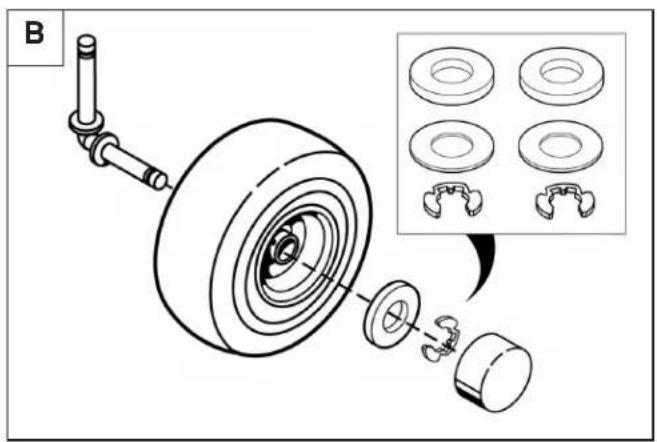
natural_image
Technical line drawing of a mechanical component with no visible text or symbolsHERUNTERFAHREN DES TRAKTORS VON DER PALETTE
natural_image
Line drawing of a tractor on a ramp with motion arrow indicating speed (no text or symbols)ZUSAMMENBAU DES MÄHWERKS

natural_image
Technical line drawing of a mechanical device with internal components and an arrow indicating direction (no text or symbols)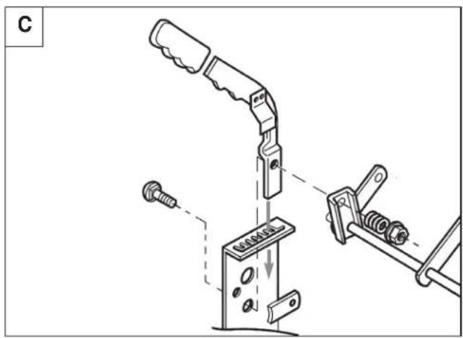

natural_image
Technical line drawing of a mechanical assembly with a tool and circular component (no text or symbols)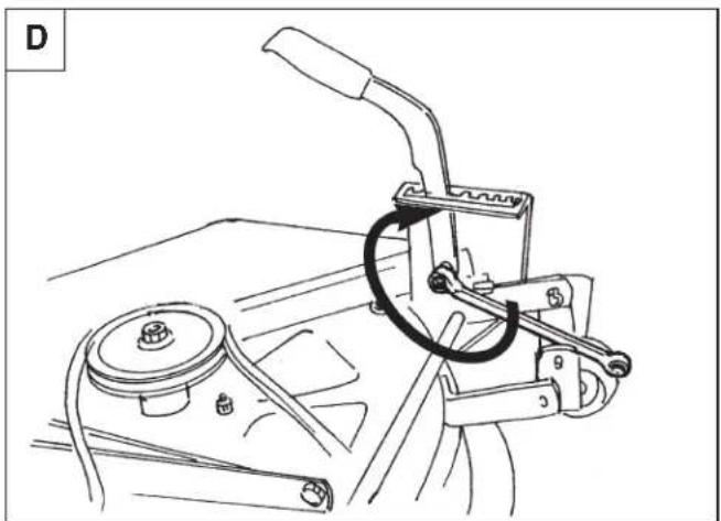
natural_image
Technical line drawing of a mechanical device with lever and handle (no text or symbols)Zusammenbau

natural_image
Technical diagram of a mechanical assembly with bolts and brackets (no text or symbols)

natural_image
Technical line drawing of a mechanical assembly with no visible text or symbols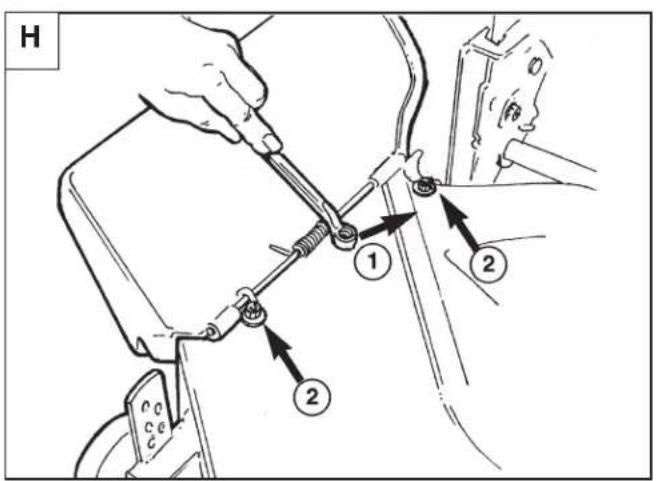
natural_image
Illustration of a person standing beside a cleaning robot with a tool, no text or symbols present
VORSICHT

natural_image
Illustration of a family cleaning a small electric tool with an adult guiding them (no text or symbols)FAHREN MIT DEM TRAKTOR
natural_image
Illustration of a person using a trolley to record a mirror outdoors near a tree and a small figure (no text or symbols)TRAKTOR SCHIEBEN
natural_image
Technical line drawing of a mechanical device with an inset close-up showing a circular component detail (no text or symbols)
natural_image
Technical line drawing of a mechanical device with levers and gears (no text or symbols)natural_image
Line drawing of a robotic arm holding a small electronic device with labeled components (no text or symbols present)natural_image
Technical line drawing of a mechanical component with two circular parts and directional arrows indicating movement (no text or symbols)natural_image
Technical line drawing of a mechanical component with mounting holes and internal ribs (no text or symbols)natural_image
Technical line drawing of a mechanical assembly with labeled component A (no text or symbols beyond label)flowchart
graph TD
    A["A"] --> B["B"]
    B --> C["C"]
    C --> A
natural_image
Line drawing of a grass lawn mower with labeled component (A), no text or symbols presentMünchner Straße 17–21
A-6330 Kufstein
Lechner
Geschäftsführer
Marketing
Chère cliente, cher client,
natural_image
Line drawing of a grass tractor with visible wheels and side control knob (no text or symbols)Décalcomanie - Danger
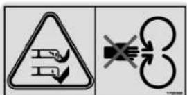
natural_image
Line drawing of a chair with four legs and two side feet, showing seat structure and directional arrows (no text or symbols)Assemblage

natural_image
Mechanical assembly diagram showing lever mechanism and component labels (no readable text or symbols)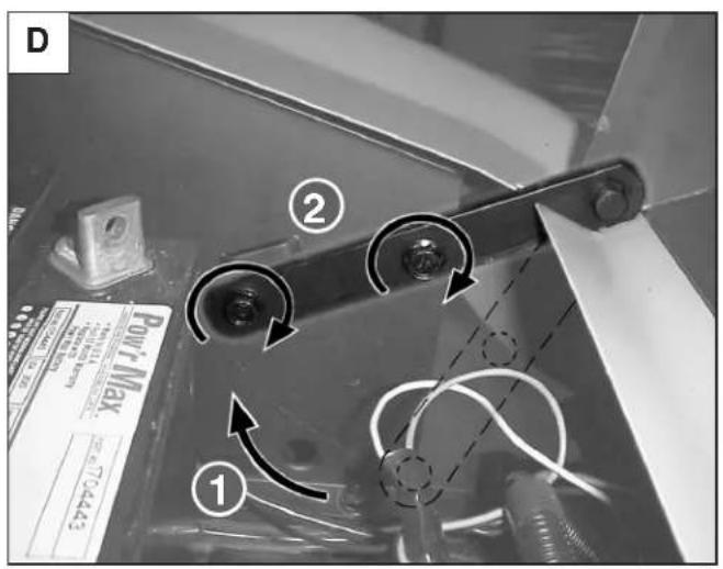
MONTAGE DES ROUES
Roues arrière

natural_image
Line drawing of hands using a tool to adjust or install a mechanical component, no text or symbols present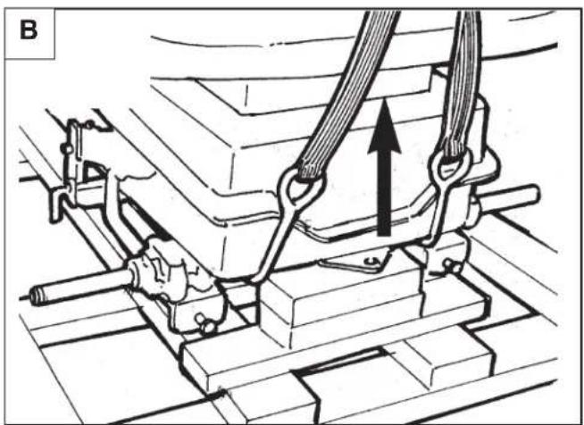
natural_image
Mechanical assembly diagram showing a lever mechanism with upward force arrow (no text or labels)
natural_image
Technical diagram of a mechanical assembly with no visible text or symbols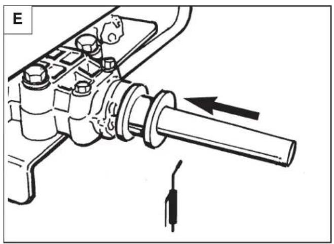
natural_image
Mechanical assembly diagram showing a shaft and housing with a directional arrow indicating motion (no text or symbols)
natural_image
Exploded view diagram of a mechanical assembly showing components like gears and shafts (no text or labels)
natural_image
Diagram showing concentric elliptical wave patterns with a black arrow pointing to a small particle (no text or symbols)
natural_image
Collection of mechanical washers and cylindrical components (no text or labels)
natural_image
Diagram of concentric circular patterns with a black arrow pointing to a small oval shape, no text or symbols present.natural_image
Diagram showing concentric circular patterns with a black arrow pointing to a small object, no text or symbols present.
natural_image
Technical line drawing of a mechanical component with no visible text or symbolsENLEVEMENT DU TRACTEUR DE LA PALETTE
natural_image
Line drawing of a robotic car on a multi-track platform with motion arrows (no text or symbols)ASSEMBLAGE DE LA BARRE DE COUPE
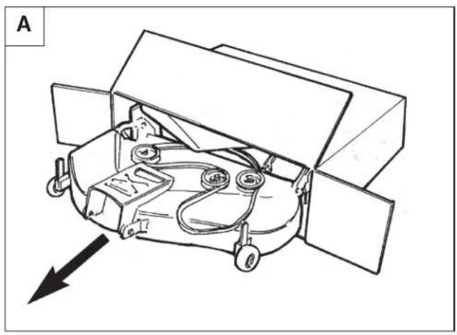
natural_image
Technical line drawing of a mechanical device with internal components and an arrow indicating direction (no text or symbols)
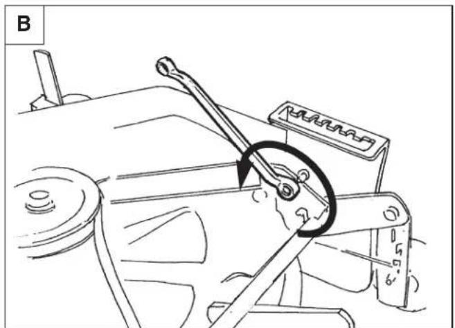
natural_image
Technical line drawing of a mechanical assembly with a tool and circular component (no text or symbols)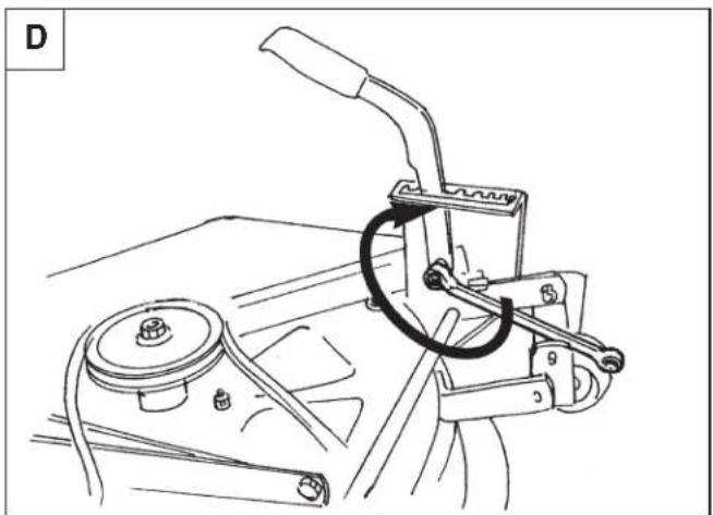
natural_image
Technical line drawing of a mechanical device with lever and handle (no text or symbols)Assemblage
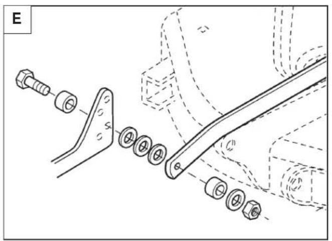
natural_image
Technical diagram of a mechanical assembly with bolts and brackets (no text or symbols)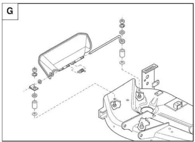
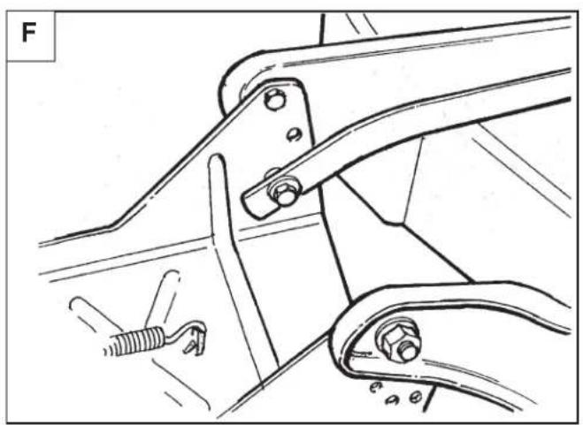
natural_image
Technical line drawing of a mechanical assembly with no visible text or symbols
natural_image
Line drawing of a person standing beside a cleaning robot (no text or symbols)CONTROLES AVANT LE DEMARRAGE
natural_image
Illustration of a child and adults interacting with a cleaning robot, no text or symbols presentCONDUITE DU TRACTEUR
natural_image
Illustration of a person playing a tennis rink with a racket, another person standing near a tree (no text or symbols)DEPLACEMENT DU TRACTEUR A LA MAIN
flowchart
graph TD
    A["A"] -->|Arrow| D["D"]
    D -->|Arrow| E["E"]
    E --> F["Central Box"]
    F --> G["G"]
    G --> B["B"]
    B --> C["C"]
    C --> F
    F --> F1["Arrow to C"]
    F --> F2["Arrow to C"]
    F --> F3["Arrow to C"]
    F --> F4["Arrow to C"]
    F --> F5["Arrow to C"]
    F --> F6["Arrow to C"]
    F --> F7["Arrow to C"]
    F --> F8["Arrow to C"]
    F --> F9["Arrow to C"]
    F --> F10["Arrow to C"]
    style F fill:#f9f,stroke:#333,stroke-width:2px
    note right of F AVANT
natural_image
Technical line drawing of a mechanical assembly with an inset close-up showing a component detail (no text or symbols)natural_image
Technical line drawing of a mechanical assembly with no visible text or symbolsFigure 24. Equilibrage de la lame
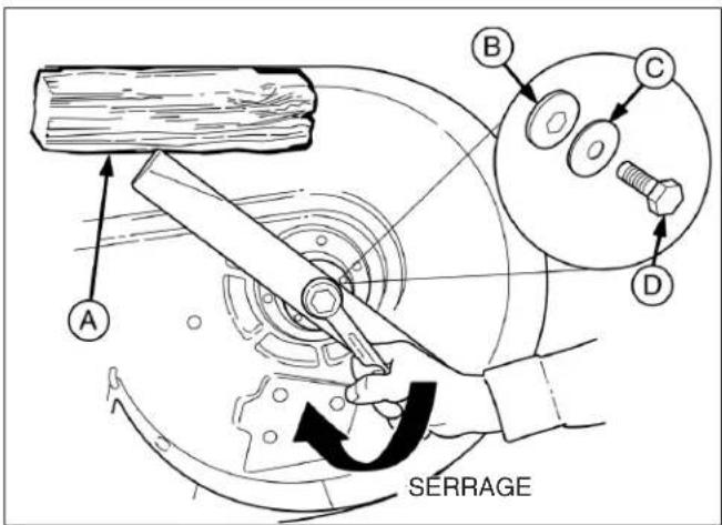
Figure 25. Installation de la lame
A. Bloc de bois de 100x100 mm C. Rondelle-ressort
B. Rondelle hexagonale D. Boulon de lame
natural_image
Line drawing of a robotic arm holding a small electronic device with labeled components (no text or symbols present)natural_image
Technical line drawing of a mechanical component with two circular parts and directional arrows indicating movement (no text or symbols)natural_image
Technical line drawing of a mechanical component with mounting holes and internal features (no text or symbols)natural_image
Technical line drawing of a mechanical assembly with labeled component A (no text or symbols beyond label)flowchart
graph TD
    A["A"] --> B["B"]
    B --> C["C"]
    C --> A
natural_image
Line drawing of a grass lawn mower with labeled component (A), no text or symbols presentMünchner Straße 17–21
A-6330 Kufstein
Lechner