IAN 273599 - Metal detector POWERFIX - Free user manual and instructions
Find the device manual for free IAN 273599 POWERFIX in PDF.



| Product type | Multifunction metal detector |
| Brand | Powerfix |
| Model | IAN 273599 |
| Power supply | 9 V battery (included) |
| Detection technology | Ultrasound, capacitive detection (wood, metal, live wires) |
| Measurement function | Ultrasound distance (0.6 to 16 m) |
| Laser | Class 2, 635-660 nm, power < 1 mW |
| Detection modes | Wood (STUD), Live wires (AC WIRE), Metal (METAL) |
| Units of measurement | Meters (m) or feet (ft) |
| Measurement functions | Distance, area, volume, addition |
| Bubble level | Yes, for horizontal alignment |
| Holding needles | Yes, for laser marking on soft surfaces |
| Display | LCD screen with signal strength and voltage indicator |
| Sound signal | Yes, when detecting an object |
| Maintenance | Clean with a soft, dry cloth |
| Safety | Class 2 laser : do not look into the beam. Do not open the housing. |
| Warranty | 3 years from date of purchase |
| Application areas | Detection of metals, live electrical cables, wooden beams; distance measurement |
Frequently Asked Questions - IAN 273599 POWERFIX
User questions about IAN 273599 POWERFIX
0 question about this device. Answer the ones you know or ask your own.
Ask a new question about this device
Download the instructions for your Metal detector in PDF format for free! Find your manual IAN 273599 - POWERFIX and take your electronic device back in hand. On this page are published all the documents necessary for the use of your device. IAN 273599 by POWERFIX.
USER MANUAL IAN 273599 POWERFIX
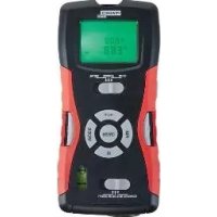
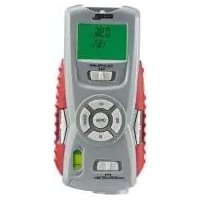
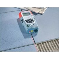
MULTI-PURPOSE DETECTOR
GB IE NI
MULTI-PURPOSEDETECTOR
Operation and Safety Notes
DK
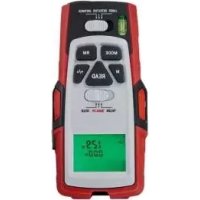
MULTIFUNKTIONSDETEKTOR
GB/IE/NI Operation and
Safety Notes Page 8
DK Brugs- og
Introduction......Page 9
Intended use ......Page 9
Description of parts ......Page 9
Technical data ......Page 10
Scope of delivery......Page 10
Safety instructions......Page 11
General safety information ......Page 11
Information regarding
inaccurate measurement results.....Page 13
Safety instructions for batteries /
rechargeable batteries......Page 14
Preparing for use......Page 16
Inserting / replacing the
battery......Page 16
Use......Page 16
Measuring distances ......Page 16
Setting the measuring unit......Page 17
Avoiding measuring errors......Page 18
Addition of distances......Page 19
Measuring surface areas......Page 19
Addition of surface areas......Page 20
Measuring volumes ......Page 21
Addition of volumes......Page 21
Detection of various objects......Page 22
Detection of wooden objects......Page 24
Tips on measurement......Page 24
Laser marking......Page 26
Troubleshooting......Page 27
Cleaning and care......Page 28
We congratulate you on the purchase of your new product. You have chosen a high quality product. The instructions for use are part of the product. They contain important information concerning safety, use and disposal. Before using the product, please familiarise yourself with all of the safety information and instructions for use. Only use the product as described and for the specified applications. If you pass the product on to anyone else, please ensure that you also pass on all the documentation with it.
Intendeduse
This product is intended for the detection of metal, wood and live wires. The product is not intended for commercial use.
• Description of parts
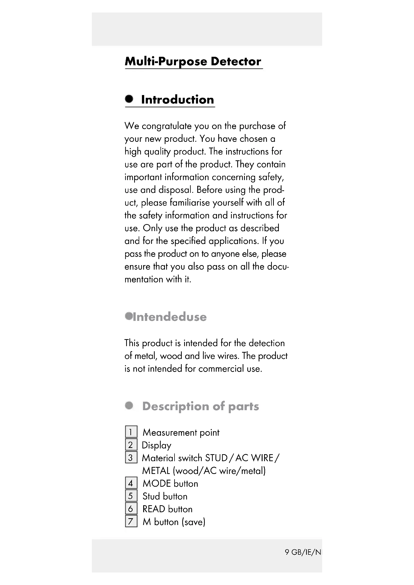
1 Measurement point
2 Display
3 Material switch STUD/AC WIRE/
METAL (wood/AC wire/metal)
4 MODE button
5 Stud button
6 READ button
7 M button (save)
8
Vial
9 Function switch LASER/DETECTOR/DISTANCE
10 RM button (read memory)
11 Stud button
12 + / = -button
13 Battery compartment
14 PUSH button
15 Laser beam opening
16 Ultrasonic sender/receiver
●Technicaldata
Ultrasonic distance measurement
Detects:Wood,AC
wires, metal
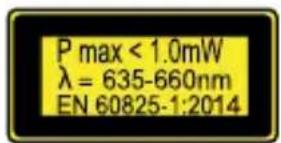
Laser class: 2
Max. power output ( P_max ): < 1 mW
Wave length: 635-660 nm
Power supply: 9 V block
battery

- Scope of delivery
1 Multi-purpose detector
1 9 V block battery
1 Operating instructions
●Safetyinstructions

General safety information
This product can be used by children aged from 8 years and above and persons with reduced physical, sensory or mental capabilities or lack of experience and knowledge if they have been given supervision or instruction concerning use of the product in a safe way and understand the hazards involved. Children shall not play with the product. Cleaning and user maintenance shall not be made by children without supervision.
■ Do not expose the product to
- extreme temperatures,
- strong vibrations,
– strong mechanical stresses, - direct sunlight,
- magnetic fields,
- moisture.
These can cause damage to the product.
■ Never immerse the product in water. Never hold the product under running water. This may lead to the product becoming damaged.
- Do not use the product in hospitals or other medical facilities. The product may affect the function of life support systems.
- Check the product for damage before use. Never use a damaged product.

CAUTION! Never open the product
casing. This can result in injury and damage to the product. Repairs must only be carried out by a qualified electrician.


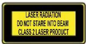
The product contains a
class 2 laser. Never point the product at yourself,
other persons or animals. Never look into the laser beam. Even a weak laser beam can cause eye damage.
■ Never direct the laser beam onto reflective surfaces or materials. Reflected lasers beams are dangerous and can get into the eyes. This could result in serious eye injuries.
■ The product is not a toy and should be kept out of the reach of children. One misapplication can lead to irreparable eye damage.
■ Only use the product in areas of application for which it was designed!
The product may neither be manipulated nor modified as they can influence the safety of the product.
No responsibility is assumed for accidents that may result from improper use and non-compliance with these Safety Instructions.
- Do not open the product housing. The guarantee lapses in cases of unauthorised tampering. Your product does not require any specific maintenance.
- Do not use the product to detect alternating current in exposed or uninsulated wires.
- Do not use the product as a replacement voltmeter.
■ Exercise caution with studs. These are sharp and can cause injury.

WARNING! Be careful when pressing the stud buttons 5, 11. The sharp needles can cause injury (see Fig. E).

Information regarding inaccurate measurement results
Please note that inaccurate measurement results can be obtained under certain conditions. The following conditions can cause inaccurate measurement results:
- very thick walls
- weak battery
- deep-lying wires or pipes
- shielded AC wires
- thick walls with thin pipes or wires
- metal-clad walls
- very damp conditions
■ Using this product you cannot detect wires in an electric circuit
- that are insulated from the mains power supply.
- that have a direct current flowing through them.
- that are used for computer or telecommunication systems.
This product is only suitable for detecting metal pipes. You cannot detect pipes made of plastic or other non-metallic materials with this product.

Safetyinstructions for batteries / rechargeable batteries
■ DANGER TO LIFE! Keep batteries/rechargeable batteries out of reach of children. If accidentally swallowed seek immediate medical attention.
DANGER OF EXPLO-
SION! Never recharge non-rechargeable batteries.
Do not short-circuit batteries / rechargeable batteries and / or open them. Overheating, fire or bursting can be the result.
■ Never throw batteries/rechargeable batteries into fire or water.
Do not exert mechanical loads to batteries/rechargeable batteries.
Risk of leakage of batteries / rechargeable batteries
- Avoid extreme environmental conditions and temperatures, which could affect batteries/rechargeable batteries, e.g. radiators/direct sunlight.
Avoid contact with the skin, eyes and mucous membranes. In the event of contact with battery acid, thoroughly flush the affected area with plenty of
clean water and seek immediate medical attention.

WEAR PROTECTIVE
GLOVES! Leaked or damaged batteries/ rechargeable batteries can cause burns on contact with the skin. Wear suitable protective gloves at all times if such an event occurs.
In the event of a leakage of batteries / rechargeable batteries, immediately remove them from the product to prevent damage.
■ Remove the batteries/rechargeable batteries if the product will not be used for a longer period.
Risk of damage of the product
Only use the specified type of battery/rechargeable battery!
- Insert batteries/rechargeable batteries according to polarity marks (+) and (-) on the battery / rechargeable battery and the product.
- Clean the contacts on the battery / rechargeable battery and in the battery compartment before inserting!
■ Remove exhausted batteries / rechargeable batteries from the product immediately.
● Preparing for use
- Inserting / replacing the battery
Note: Remove the foil from battery before inserting into battery compartment 13.
☐ Open the battery compartment 13 on the back of the product.
☐ Remove the spent battery, if necessary.
☐ Insert a new 9 V block battery into the battery compartment. Check the polarity of the battery during insertion!
☐ Ensure that the band for easy removal of the battery lies under the 9 V block battery. Press the battery firmly into battery compartment.
☐ Close the battery compartment again. The battery compartment lid locks noticeably and audibly into place.
Note: When the battery symbol 📄 appears in the display 2 replace the battery. With a weak battery you may receive an inaccurate or false measurement result.
Use
Measuringdistances
-
Slide the function switch 9 to the position „DISTANCE“. The display 2 is turned on.
-
Hold the product horizontally to the wall at the distance you wish to measure.
The ultrasonic - transmitter / receiver 16 must point at the wall at a right angle. Use the vial to do this 8 direct the product so that the air bubble in the vial lies between the two marker lines.
- Press the READ button 6 The measured distance appears in the display.
Note: Hold down the READ button and move the product and move the product further over the surface to be measured. The product measures the distance continuously. These are displayed in the display.
Settingthe measuring unit
You can choose between the measuring units of metre (m) and foot ('...").
☐ Measure a distance as described in the section „Measuring distances“. As an example, „2m“ will appear on the display.
☐ In order to set the measuring unit of foot, proceed as described in step 1 to 3:
-
Press the MODE button 4 and keep it pressed.
-
Press the READ button 6 while keeping the MODE button pressed.
-
To set the measuring unit of foot release the READ button first, followed by the MODE button. As an example, "6'07"' will appear on the display if you have measured a distance of 2 m.
-
In order to switch between the measuring units of foot and metre once again, proceed as described in step 1 to 3.
- Avoidingmeasuring errors
In order to avoid measuring errors, please note the following information:
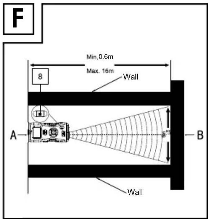
The measurement is performed by ultrasound, which travels from the ultrasonic sender/receiver 16 in a conical manner.
The ultrasound is reflected from the target area and received by the ultrasonic receiver.
The product calculates the measured length (Fig. F) from the travel time of the signal.
In order to guarantee an exact measurement, the following conditions must be maintained (Fig. F):
- The reference area (A) must be parallel to the target area (B).
- The distance to be measured must be between 0.6 m and 16 m long.
- There must be no objects in the conical path of the ultrasound, which could reflect the ultrasound prematurely. The conical path of the ultrasound has a width of about 6 m at a length of 16 m.
- The target area must have a smooth surface, so that the ultrasound can be well reflected.
- Transparent surfaces, such as glass, generally reflect the ultrasound.
- The battery must not be empty. An empty battery is shown in the display 2 by the battery symbol
- If a definitive measurement is not possible, the display shows the „Err“ information. The measurement must then be repeated.
- Addition of distances
With the product you can add the measured distances together:
- Measure the first distance as described in the section „Measuring distances“.
- Press the + / = button 12. The message „+“ appears in the display 2 and the measured distance in the row below.
- Measure the next distance. The new distance measured is shown in the upper row of the display.
- Press the + / = button again. The new measurement is added to the old in the lower row.
- Repeat steps 3 to 4 to add further measurements.
- Press the MODE button 4 to leave the addition mode. All the measurements will be deleted.
●Measuring surface areas
-
Slide the function switch 9 to the position „DISTANCE“. The display 2 is turned on.
-
Press the MODE button 4 once. The message „L“ (length) appears in the display.
- Press the READ button 6 to measure the length. The measured length appears in the upper row of the display and the message „W“ (width) starts to blink.
- Press the READ button to measure the width. The measured width appears in the upper row of the display. The results of the surface area calculation appear in the lower row.
●Addition of surface areas
- Measure an area as described in the section „Measuring surface areas“.
- Press the M button 7 The message „M+“ appears in the display 2 The measured surface area is saved.
- Press the MODE button 4. The product is now ready for the second measurement.
- Measure the next surface area.
- Press the + / = button 12. The message „+“ appears in the display.
- Press the RM button 10. The result of the first measurement is shown in the lower row of the display.
-
Press the + / = button again. Both measurements are added and the result is shown in the lower row of the display.
-
Repeat steps 2 to 7 to add further measurements.
- Press the MODE button 4 to leave the addition mode. All the measurements will be deleted.
Measuring volumes
- Slide the function switch 9 to the position „DISTANCE“. The display 2 is turned on.
- Press the MODE button 4 twice. The message „L“ (length) appears in the display.
- Press the READ button 6 to measure the length. The measured length appears in the upper row of the display and the message „W“ (width) starts to blink.
- Press the READ button to measure the width. The measured width appears in the upper row of the display and the message „H“ (height) begins to blink.
- Press the READ button to measure the height. The measured height appears in the upper row of the display. The results of the volume calculation appear in the lower row.
• Addition of volumes
-
Measure a volume as described in the section „Measuring volumes“.
-
Press the M button 7 The message „M+“ appears in the display 2 The measured volume is saved.
- Press the MODE button 4. The product is now ready for the second measurement.
- Measure the next volume.
- Press the + / = button 12. The message „+“ appears in the display.
- Press the RM button [10] . The result of the first measurement is shown in the lower row of the display.
- Press the + / = button again. Both measurements are added and the result is shown in the lower row of the display.
- Repeat steps 2 to 7 to add further measurements.
- Press the MODE button to leave the addition mode. All the measurements will be deleted.
- Detection of various objects
The detection of hidden objects is the same in all three modi (STUD, AC WIRE, METAL).
Please note: Test the product before initial use on a metal pipe or AC wire whose position you know exactly.
- Slide the function switch 9 to the position „DETECTOR“.
-
Slide the material switch 3 to the position STUD, AC WIRE or METAL (wood, AC wire or metal).
-
Calibrate the multi-purpose detector by holding it flat at the desired point on the wall.
-
Guide the detector over a location on the surface to be examined, where you know that there is no object, which you are looking for. Then press the PUSH button 14 and keep it pressed down. Guide the detector, with the underside flat, over the surface to be examined. It is possible that during this some short signal tones may sound. These are however without any meaning, so long as no intensity display 2 appears in the device display (Fig. D).
-
If there is an object, for which the search is activated, in the vicinity of the detector, several bars appear at first on the intensity display. As proximity to the search object increases, the number of bars increases on the intensity display (Fig. D).
-
If the detector is exactly over the search object, a continuous signal tone sounds.
-
In the case of a search for a power line, the voltage sign (A) also appears in addition to the intensity display.
- Detection of wooden objects
- For the detection of wooden objects, proceed as described in the section „Detection of various objects“.
- If you have found something with the multi-purpose detector, mark it.
- To be sure that the found object is made of wood, slide the material switch 3 to the position "METAL". Look for metal at the same point.
- If the product does not find anything at this point in the mode "METAL", the object is made of wood. If the product finds an object at this point in the modus "METAL", then the object is made of metal.
- In this case, look in a different place in the "STUD" mode, and repeat steps 1 to 4.
- Tips on measurement
- The calibration button must remain pressed during the entire search process (calibration and search).
- If you calibrate too closely to the object or directly on the object, the calibration can fail. If the calibration fails, the LC display shows the full intensity and a long beeping tone sounds or can't search any object in the wall.
- Move and hold the device several centimeters further to the right or left of the
previous surface and recalibrate. Start the search process.
- Repeat several times to ensure the detection accuracy.
- Incorrect measurements can occur depending on the nature of the examined wall. Check therefore before every measurement the position of a known wooden or metal beam, of a known void or a known power line. If these are not detected by the device, the substrate is not suitable for a search with this device.
- Avoid touching the LC display during measurements as it may affect the accuracy of the device.
- Please note that power lines can also be located as metal or as beams. Always use the additional voltage search, so that you can exclude any incorrect interpretations.
- Please note that metal beams are also detected in the Beam search „STUD“ function. If you find a beam and you want to be sure that it is not a metal beam (or for example a water pipe), use the additional Metal search “METAL”.
- Depending on the wall thickness and material, it is possible that the detector may signal a finding, before it is over the material. In this case mark the start and end of the signalled area at the indentation of the measuring head. The middle of the sought object lies in the middle between the two markings.
- Please note that metal objects are located more readily the easier they can be magnetized.
- This means that iron is detected at a significantly greater distance than copper for example.
- Please note that power lines can only be detected as such, if they are carrying voltage.
- Light switches must always therefore be switched on, so that the conductor is carrying voltage. All the fuses must similarly be inserted or switched on.
- Please note that only voltages of 230V \~ 50 Hz are detected.
Lasermarking
Use the laser marking function to align pictures, cupboards, and other things, vertically or horizontally.
☐ Slide the function switch 9 to the position „LASER“. A laser line is produced.
Horizontal laser line
-
Hold the multi-purpose detector horizontally to the wall. To do this, direct the product so that the air bubble in the vial 8 lies between the two marker lines.
-
Slide the two stud buttons 5 11 firmly downwards. The nails lightly penetrate the wall to prevent the multi-detector from falling.
Note: Exercise care with the studs.
These are sharp and can cause injury. Do not use the stud button on stone or metal wall, but only on walls with a soft surface.
Vertical laser line
- Attach a thread to the eye at the measuring point 1.
- Hang the product to the point on the wall where you would like to project the vertical line. The product hangs vertically downwards like a plumb bob. The laser projects a vertical line on the wall.
●Troubleshooting
This product has delicate electronic components. This means that if it is placed near an object that transmits radio signals, it could cause interference. If false readings occur, remove such equipment from the vicinity of the product.
- Electromagnetic interference/high-frequency emissions can lead to the product failing. In cases of the product failing to work, remove the batteries for a short while and then replace them. Do this as described in the section "Inserting/changing the batteries".
- Cleaning and care
■ Under no circumstances should you use liquids or detergents, as these will damage the product.
☐ Only clean the outside of the product with a soft, slightly damp cloth.
●Disposal

The packaging is made entirely of recyclable materials, which you may dispose of at local recycling facilities. The Green Dot is not valid for Germany.
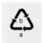
Observe the marking of the packaging materials for waste separation, which are marked with abbreviations (a) and numbers (b) with following meaning: 1-7: plastics/20-22: paper and fibreboard / 80-98: composite materials.

The product and packaging materials are recyclable, dispose of it separately for better waste treatment. The Triman logo is valid in France only.

Contact your local refuse disposal authority for more details of how to dispose of your worn-out product.
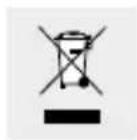
To help protect the environment, please dispose of the product properly when it has reached the end of its useful life and not in the household waste. Information on collection points and their opening hours can be obtained from your local authority.
Faulty or used batteries / rechargeable batteries must be recycled in accordance with Directive 2006/66/EC and its amendments. Please return the batteries / rechargeable batteries and / or the product to the available collection points.
Environmental damage through incorrect disposal of the batteries / rechargeable batteries!
Batteries / rechargeable batteries may not be disposed of with the usual domestic waste. They may contain toxic heavy metals and are subject to hazardous waste treatment rules and regulations. The chemical symbols for heavy metals are as follows: Cd = cadmium, Hg = mercury, Pb = lead. That is why you should dispose of used batteries / rechargeable batteries at a local collection point.
Warranty
The product has been manufactured to strict quality guidelines and meticulously examined before delivery. In the event of product defects you have legal rights against the retailer of this product. Your legal rights are not limited in any way by our warranty detailed below.
The warranty for this product is 3 years from the date of purchase. Should this product show any fault in materials or manufacture within 3 years from the date of purchase, we will repair or replace it - at our choice - free of charge to you.
The warranty period begins on the date of purchase. Please keep the original sales receipt in a safe location. This document is required as your proof of purchase. This warranty becomes void if the product has been damaged, or used or maintained improperly.
The warranty applies to defects in material or manufacture. This warranty does not cover product parts subject to normal wear, thus possibly considered consumables (e.g. batteries) or for damage to fragile parts, e.g. switches, rechargeable batteries or glass parts.
CE
Indledning....Side 32
- MULTI-PURPOSE DETECTOR
- MULTI-PURPOSEDETECTOR
- MULTIFUNKTIONSDETEKTOR
- Introduction......Page 9
- Safety instructions......Page 11
- Preparing for use......Page 16
- Use......Page 16
- Troubleshooting......Page 27
- Cleaning and care......Page 28
- Intendeduse
- • Description of parts
- ●Technicaldata
- - Scope of delivery
- ●Safetyinstructions
- General safety information
- CAUTION! Never open the product
- Information regarding inaccurate measurement results
- Safetyinstructions for batteries / rechargeable batteries
- DANGER OF EXPLO-
- Risk of leakage of batteries / rechargeable batteries
- WEAR PROTECTIVE
- Risk of damage of the product
- ● Preparing for use
- - Inserting / replacing the battery
- Use
- Measuringdistances
- Settingthe measuring unit
- - Avoidingmeasuring errors
- - Addition of distances
- ●Measuring surface areas
- ●Addition of surface areas
- Measuring volumes
- • Addition of volumes
- - Detection of various objects
- - Detection of wooden objects
- - Tips on measurement
- Lasermarking
- Horizontal laser line
- Note: Exercise care with the studs.
- Vertical laser line
- ●Troubleshooting
- - Cleaning and care
- ●Disposal
- Environmental damage through incorrect disposal of the batteries / rechargeable batteries!
- Warranty
- CE
- Indledning....Side 32
Brand : POWERFIX
Model : IAN 273599
Category : Metal detector