DHR281ZWJ - Hammer MAKITA - Free user manual and instructions
Find the device manual for free DHR281ZWJ MAKITA in PDF.

| Product type | Cordless rotary hammer |
| Brand | Makita |
| Model | DHR281ZWJ |
| Drilling capacity in concrete | 28 mm |
| Core bit capacity | 54 mm |
| Diamond core bit capacity (dry) | 65 mm |
| Drilling capacity in steel | 13 mm |
| Drilling capacity in wood | 32 mm |
| No load speed | 0 - 980 min⁻¹ |
| No load impact rate | 0 - 5 000 min⁻¹ |
| Overall length | 404 mm |
| Net weight (with battery) | 4.0 - 4.9 kg |
| Rated voltage | 36 V DC (2 x 18 V) |
| Compatible battery type | BL1815N / BL1820B / BL1830B / BL1840B / BL1850B / BL1860B |
| Compatible charger | DC18RC / DC18RD / DC18RE / DC18SD / DC18SE / DC18SF / DC18SH / DC18WC |
| Sound pressure level (LpA) | 96 dB(A) |
| Sound power level (LWA) | 104 dB(A) |
| Sound uncertainty (K) | 3 dB(A) |
| Vibrations – Drilling with hammering in concrete | 13.3 m/s² (uncertainty K=1.5 m/s²) |
| Vibrations – Chiseling | 9.3 m/s² (uncertainty K=2.4 m/s²) |
| Operating modes | Rotation with hammering, rotation only, hammering only |
| Electronic functions | Variable speed control (dial 1 to 5), constant speed control, torque limiter, active reaction detection technology (models DHR282/283) |
| Included accessories | Side handle, depth gauge, grease, SDS-plus chuck |
| Maintenance | Clean ventilation slots, replace dust filter if equipped, have repairs done at an authorized Makita service center |
Frequently Asked Questions - DHR281ZWJ MAKITA
User questions about DHR281ZWJ MAKITA
0 question about this device. Answer the ones you know or ask your own.
Ask a new question about this device
Download the instructions for your Hammer in PDF format for free! Find your manual DHR281ZWJ - MAKITA and take your electronic device back in hand. On this page are published all the documents necessary for the use of your device. DHR281ZWJ by MAKITA.
USER MANUAL DHR281ZWJ MAKITA
natural_image
Technical line drawing of a mechanical device with no visible text or symbols
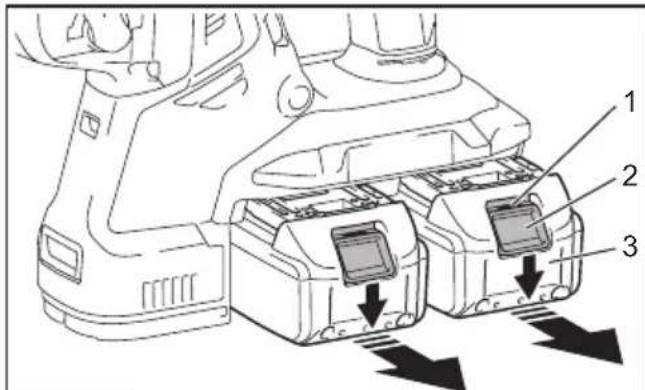
Fig.1
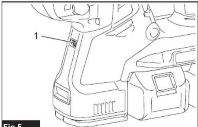
Fig.5
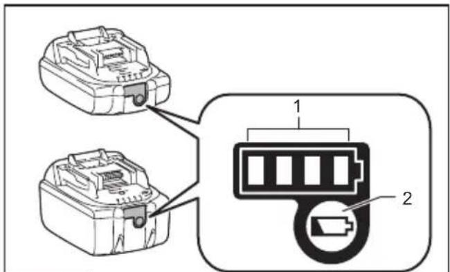
Fig.2
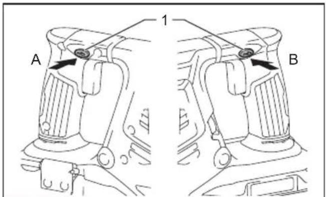
Fig.6
natural_image
Technical line drawing of a mechanical device with labeled component 1, no readable text or symbols present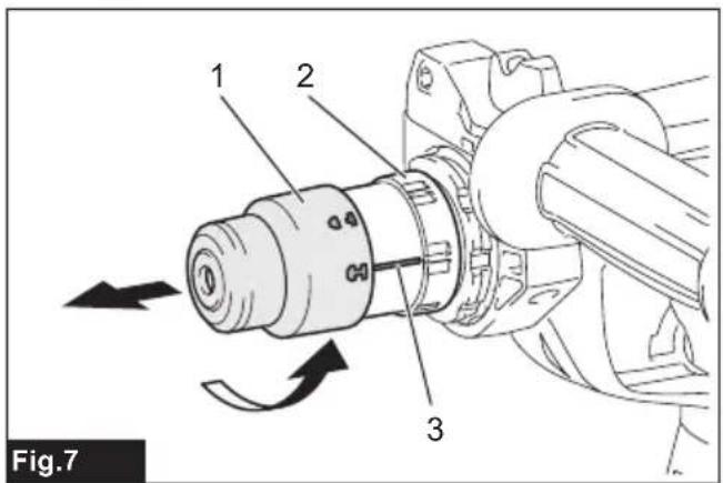
natural_image
Technical line drawing of a mechanical component with labeled parts (no text or symbols beyond label)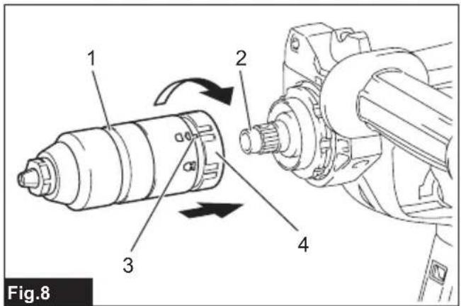

natural_image
Technical line drawing of a mechanical device with a clamp and labeled component (no text or symbols beyond label)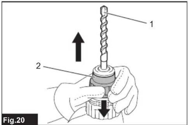
natural_image
Technical line drawing of a mechanical device with an arrow indicating assembly or adjustment, showing internal components and parts (no text or symbols)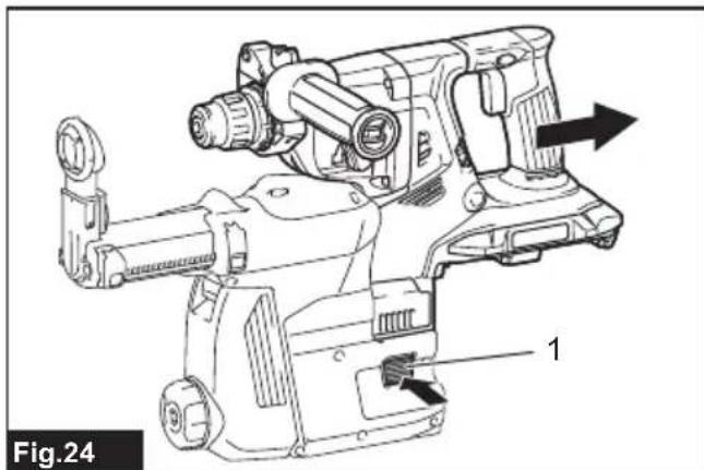
natural_image
Technical line drawing of a mechanical device with labeled parts and directional arrows (no text or symbols beyond labels)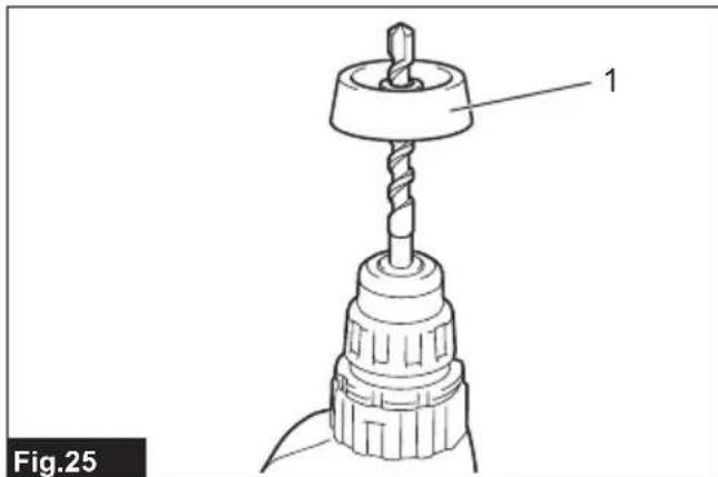
natural_image
Technical line drawing of a drill bit with a drill bit head and spiral drill bit (no text or symbols)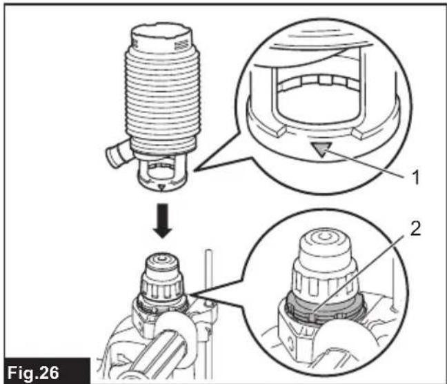
natural_image
Mechanical assembly diagram showing a piston-like component inserted into a housing, with an upward arrow indicating motion (no text or symbols present)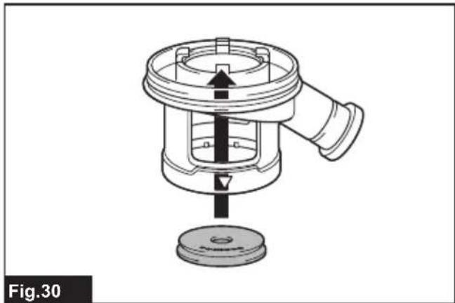
natural_image
Technical diagram of a mechanical component with a central shaft and base, labeled Fig.30 (no text or symbols on the diagram itself)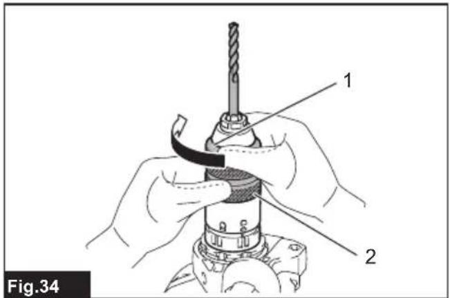
natural_image
Line drawing of a drill bit with a drill bit being inserted into a housing (no text or symbols)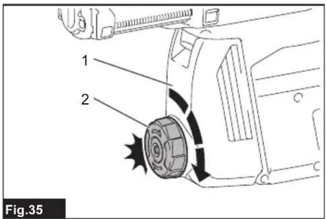
natural_image
Line drawing of a hand using a drill bit to drive a spark plug (no text or symbols)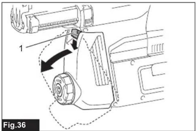
natural_image
Technical line drawing of a mechanical component with labeled part '1' and an arrow indicating direction (no text or symbols beyond label)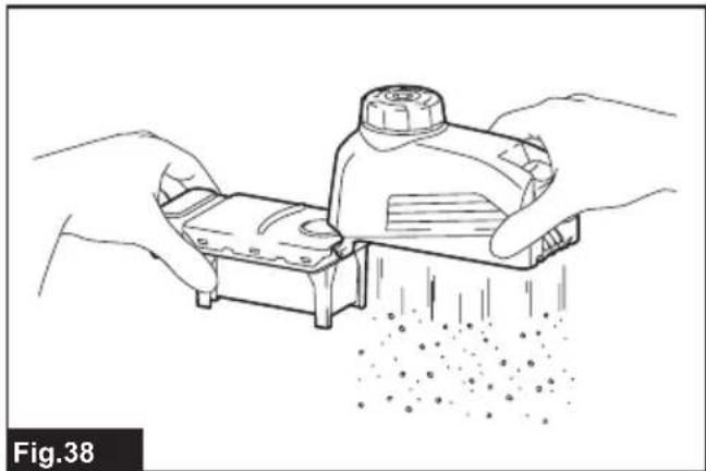
natural_image
Illustration of hands using a tool to spread material from a small container (no text or symbols)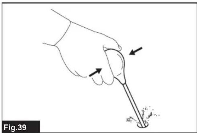
natural_image
Illustration of a hand holding a tool with arrows indicating motion or force direction (no text or symbols)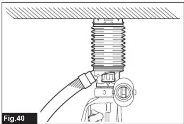
natural_image
Technical diagram of a mechanical assembly with threaded component and connecting rod (no text or symbols)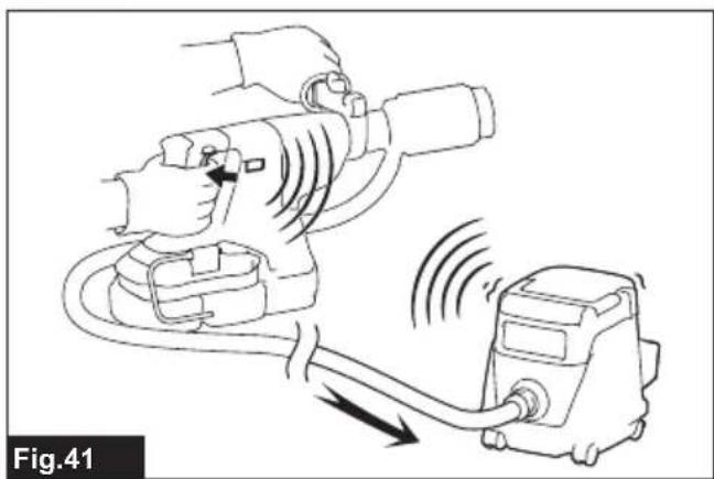
natural_image
Line drawing of a hand operating a drill press connected to a control unit, showing motion lines (no text or symbols)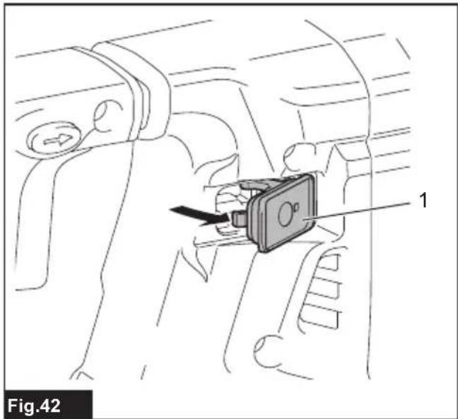
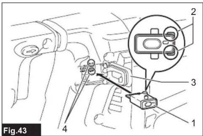
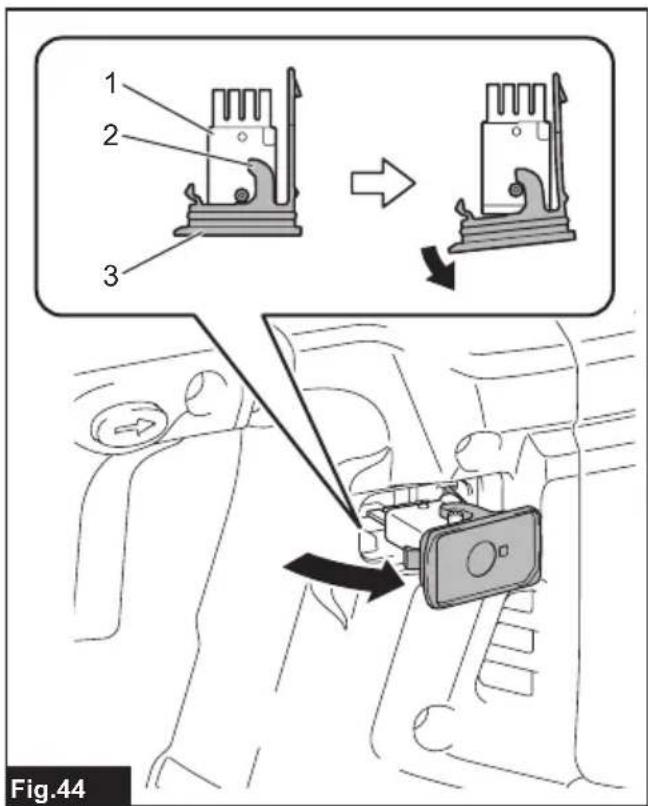
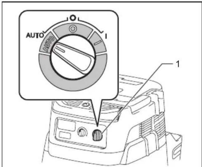
Fig.45

Fig.48

natural_image
Line drawing of a mechanical device connected to a small cylindrical device (no text or symbols)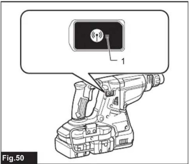
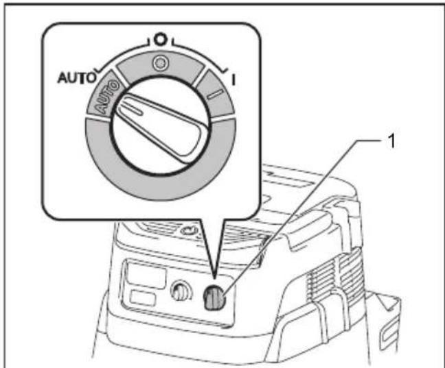
Fig.51
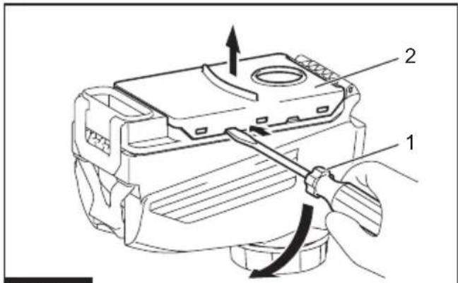
Fig.54
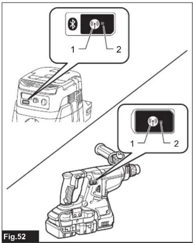
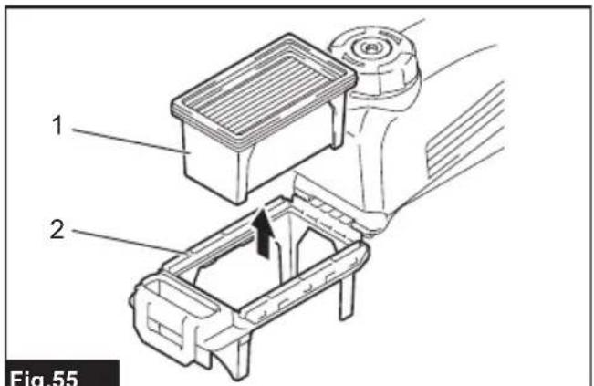
Fig.55
SPECIFICATIONS
| Model: DHR280 DHR281 DHR282 DHR283 | |||||
| Capacities Concrete 28 mm | |||||
| Core bit 54 mm | |||||
| Diamond core bit (dry type) 65 mm | |||||
| Steel 13 mm | |||||
| Wood 32 mm | |||||
| No load speed 0 - 980 min | -1 | ||||
| Blows per minute 0 - 5,000 min | -1 | ||||
| Overall length 373 mm 404 mm 373 mm 404 mm | |||||
| Rated voltage D.C. 36 V | |||||
| Net weight | 3.8 - 4.9 kg | 4.0 - 4.9 kg | 3.9 - 5.0 kg | 4.0 - 4.9 kg | |
Optional accessory
| Model: | DX08 (For DHR280/DHR282) | DX09 (For DHR281/DHR283) |
| Suction performance | 350 l/min | |
| Operating stroke | Up to 190 mm | |
| Suitable drill bit | Up to 260 mm | |
| Rated voltage D.C. 18 V | ||
| Net weight | 1.6 kg | |
• Due to our continuing program of research and development, the specifications herein are subject to change without notice.
• Specifications and battery cartridge may differ from country to country.
- The weight may differ depending on the attachment(s), including the battery cartridge. The lightest and heaviest combinations, according to EPTA-Procedure 01/2014, are shown in the table.
Applicable battery cartridge and charger
| Battery cartridge | BL1815N / BL1820B / BL1830B / BL1840B / BL1850B / BL1860B |
| Charger | DC18RC / DC18RD / DC18RE / DC18SD / DC18SE / DC18SF / DC18SH / DC18WC |
• Some of the battery cartridges and chargers listed above may not be available depending on your region of residence.
⚠ WARNING: Only use the battery cartridges and chargers listed above. Use of any other battery cartridges and chargers may cause injury and/or fire.
Recommended cord connected power source
| Battery adapter | BAP182 |
• The cord connected power source(s) listed above may not be available depending on your region of residence.
• Before using the cord connected power source, read instruction and cautionary markings on them.
Intended use
The tool is intended for hammer drilling and drilling in brick, concrete and stone as well as for chiselling work. It is also suitable for drilling without impact in wood, metal, ceramic and plastic.
Noise
The typical A-weighted noise level determined according to EN62841-2-6:
Model DHR280
Sound pressure level ( L_pA ): 96 dB (A)
Sound power level ( L_WA ): 104 dB (A)
Uncertainty (K) : 3 dB (A)
Model DHR281
Sound pressure level ( L_pA ): 96 dB(A)
Sound power level ( L_WA ): 104 dB (A)
Uncertainty (K) : 3 dB(A)
Model DHR282
Sound pressure level (L _pA ) : 96 dB(A)
Sound power level (LWA): 104 dB (A)
Uncertainty (K) : 3 dB(A)
Model DHR283
Sound pressure level (L _pA ) : 96 dB(A)
Sound power level ( L_WA ): 104 dB (A)
Uncertainty (K) : 3 dB(A)
Sound power level (LWA): 105 dB (A)
Uncertainty (K) : 3 dB(A)
NOTE: The declared noise emission value(s) has been measured in accordance with a standard test method and may be used for comparing one tool with another.
NOTE: The declared noise emission value(s) may also be used in a preliminary assessment of exposure.

WARNING: Wear ear protection.
⚠ WARNING: The noise emission during actual use of the power tool can differ from the declared value(s) depending on the ways in which the tool is used especially what kind of workpiece is processed.
⚠ WARNING: Be sure to identify safety measures to protect the operator that are based on an estimation of exposure in the actual conditions of use (taking account of all parts of the operating cycle such as the times when the tool is switched off and when it is running idle in addition to the trigger time).
Vibration
The following table shows the vibration total value (tri-axial vector sum) determined according to applicable standard.
Model DHR280
| Work mode Vibration emission | Uncertainty (K) | Applicable standard / Test condition |
| Hammer drilling into concrete ( a_t, HD ) | 14.5 m/s ^2 | 2.8 m/s ^2 EN62841-2-6 |
| Work mode Vibration emission | Uncertainty (K) | Applicable standard / Test condition |
| Hammer drilling into concrete with DX08 ( a_h, HD ) | 13.2 m/s^2 | 2.6 m/s^2 EN62841-2-6 |
| Chiselling ( a_h, CHeq ) | 10.8 m/s^2 | 1.5 m/s^2 EN62841-2-6 |
Model DHR281
| Work mode Vibration emission | Uncertainty (K) | Applicable standard / Test condition |
| Hammer drilling into concrete ( a_h, HD ) | 13.3 m/s ^2 | 1.5 m/s ^2 EN62841-2-6 |
| Hammer drilling into concrete with DX09 ( a_h, HD ) | 13.3 m/s ^2 | 1.5 m/s ^2 EN62841-2-6 |
| Chiselling ( a_h, CHeq ) | 9.3 m/s ^2 | 2.4 m/s ^2 EN62841-2-6 |
Model DHR282
| Work mode Vibration emission | Uncertainty (K) | Applicable standard / Test condition | |
| Hammer drilling into concrete ( a_h, HD ) | 14.5 m/s ^2 | 2.8 m/s ^2 | EN62841-2-6 |
| Hammer drilling into concrete with DX08 ( a_h, HD ) | 13.2 m/s ^2 | 2.6 m/s ^2 | EN62841-2-6 |
| Chiselling ( a_h, CHeq ) | 10.7 m/s ^2 | 1.5 m/s ^2 | EN62841-2-6 |
Model DHR283
| Work mode Vibration emission | Uncertainty (K) | Applicable standard / Test condition |
| Hammer drilling into concrete ( a_h, HD ) | 13.3 m/s ^2 | 1.5 m/s ^2 EN62841-2-6 |
| Hammer drilling into concrete with DX09 ( a_h, HD ) | 13.3 m/s ^2 | 1.5 m/s ^2 EN62841-2-6 |
| Chiselling ( a_h, CHeq ) | 9.3 m/s ^2 | 2.4 m/s ^2 EN62841-2-6 |
To optimize working efficiency, we recommend the following:
- Apply feed force to the switch handle (main handle).
- Use the side grip (auxiliary handle) to withstand reaction torque and keep balance of the tool.
This may reduce the vibration total emission values by about a third to a half of the declared values given in
the tables.
NOTE: The declared vibration total value(s) has been measured in accordance with a standard test method and may be used for comparing one tool with another.
NOTE: The declared vibration total value(s) may also be used in a preliminary assessment of exposure.
⚠ WARNING: The vibration emission during actual use of the power tool can differ from the declared value(s) depending on the ways in which the tool is used especially what kind of workpiece is processed.
WARNING: Be sure to identify safety measures to protect the operator that are based on an estimation of exposure in the actual conditions of use (taking account of all parts of the operating cycle such as the times when the tool is switched off and when it is running idle in addition to the trigger time).
Declarations of Conformity
For European countries only
The Declarations of conformity are included in Annex A to this instruction manual.
SAFETY WARNINGS
General power tool safety warnings
⚠ WARNING Read all safety warnings, instructions, illustrations and specifications provided with this power tool. Failure to follow all instructions listed below may result in electric shock, fire and/or serious injury.
Save all warnings and instructions for future reference.
The term "power tool" in the warnings refers to your mains-operated (corded) power tool or battery-operated (cordless) power tool.
CORDLESS ROTARY HAMMER SAFETY WARNINGS
Safety instructions for all operations
- Wear ear protectors. Exposure to noise can cause hearing loss.
- Use auxiliary handle(s), if supplied with the tool. Loss of control can cause personal injury.
- Hold the power tool by insulated gripping surfaces, when performing an operation where the cutting accessory may contact hidden wiring. Cutting accessory contacting a "live" wire may make exposed metal parts of the power tool "live" and could give the operator an electric shock.
Safety instructions when using long drill bits with rotary hammers
- Always start drilling at low speed and with the
bit tip in contact with the workpiece. At higher speeds, the bit is likely to bend if allowed to rotate freely without contacting the workpiece, resulting in personal injury.
- Apply pressure only in direct line with the bit and do not apply excessive pressure. Bits can bend, causing breakage or loss of control, resulting in personal injury.
Additional safety warnings
- Wear a hard hat (safety helmet), safety glasses and/or face shield. Ordinary eye or sun glasses are NOT safety glasses. It is also highly recommended that you wear a dust mask and thickly padded gloves.
- Be sure the bit is secured in place before operation.
- Under normal operation, the tool is designed to produce vibration. The screws can come loose easily, causing a breakdown or accident. Check tightness of screws carefully before operation.
- In cold weather or when the tool has not been used for a long time, let the tool warm up for a while by operating it under no load. This will loosen up the lubrication. Without proper warm-up, hammering operation is difficult.
- Always be sure you have a firm footing. Be sure no one is below when using the tool in high locations.
- Hold the tool firmly with both hands.
- Keep hands away from moving parts.
- Do not leave the tool running. Operate the tool only when hand-held.
- Do not point the tool at any one in the area when operating. The bit could fly out and injure someone seriously.
- Do not touch the bit, parts close to the bit, or workpiece immediately after operation; they may be extremely hot and could burn your skin.
- Some material contains chemicals which may be toxic. Take caution to prevent dust inhalation and skin contact. Follow material supplier safety data.
- Always be sure that the tool is switched off and the battery cartridge and the bit are removed before handing the tool to other person.
- Before operation, make sure that there is no buried object such as electric pipe, water pipe or gas pipe in the working area. Otherwise, the drill bit/chisel may touch them, resulting an electric shock, electrical leakage or gas leak.
- Do not operate the tool at no-load unnecessarily.
SAVE THESE INSTRUCTIONS.
WARNING: DO NOT let comfort or familiarity with product (gained from repeated use) replace strict adherence to safety rules for the subject product. MISUSE or failure to follow the safety rules stated in this instruction manual may cause serious personal injury.
Important safety instructions for battery cartridge
- Before using battery cartridge, read all instructions and cautionary markings on (1) battery charger, (2) battery, and (3) product using battery.
- Do not disassemble or tamper with the battery cartridge. It may result in a fire, excessive heat, or explosion.
- If operating time has become excessively shorter, stop operating immediately. It may result in a risk of overheating, possible burns and even an explosion.
- If electrolyte gets into your eyes, rinse them out with clear water and seek medical attention right away. It may result in loss of your eyesight.
- Do not short the battery cartridge:
(1) Do not touch the terminals with any conductive material.
(2) Avoid storing battery cartridge in a container with other metal objects such as nails, coins, etc.
(3) Do not expose battery cartridge to water or rain.
A battery short can cause a large current flow, overheating, possible burns and even a breakdown.
- Do not store and use the tool and battery cartridge in locations where the temperature may reach or exceed 50 °C (122 °F).
- Do not incinerate the battery cartridge even if it is severely damaged or is completely worn out. The battery cartridge can explode in a fire.
- Do not nail, cut, crush, throw, drop the battery cartridge, or hit against a hard object to the battery cartridge. Such conduct may result in a fire, excessive heat, or explosion.
- Do not use a damaged battery.
- The contained lithium-ion batteries are subject to the Dangerous Goods Legislation requirements.
For commercial transports e.g. by third parties, forwarding agents, special requirement on packaging and labeling must be observed.
For preparation of the item being shipped, consulting an expert for hazardous material is required.
Please also observe possibly more detailed national regulations.
Tape or mask off open contacts and pack up the battery in such a manner that it cannot move around in the packaging.
- When disposing the battery cartridge, remove it from the tool and dispose of it in a safe place. Follow your local regulations relating to disposal of battery.
- Use the batteries only with the products specified by Makita. Installing the batteries to non-compliant products may result in a fire, excessive heat, explosion, or leak of electrolyte.
- If the tool is not used for a long period of time, the battery must be removed from the tool.
- During and after use, the battery cartridge may
take on heat which can cause burns or low temperature burns. Pay attention to the handling of hot battery cartridges.
- Do not touch the terminal of the tool immediately after use as it may get hot enough to cause burns.
- Do not allow chips, dust, or soil stuck into the terminals, holes, and grooves of the battery cartridge. It may cause heating, catching fire, burst and malfunction of the tool or battery cartridge, resulting in burns or personal injury.
- Unless the tool supports the use near high-voltage electrical power lines, do not use the battery cartridge near high-voltage electrical power lines. It may result in a malfunction or breakdown of the tool or battery cartridge.
- Keep the battery away from children.
SAVE THESE INSTRUCTIONS.
CAUTION: Only use genuine Makita batteries. Use of non-genuine Makita batteries, or batteries that have been altered, may result in the battery bursting causing fires, personal injury and damage. It will also void the Makita warranty for the Makita tool and charger.
Tips for maintaining maximum battery life
- Charge the battery cartridge before completely discharged. Always stop tool operation and charge the battery cartridge when you notice less tool power.
- Never recharge a fully charged battery cartridge. Overcharging shortens the battery service life.
- Charge the battery cartridge with room temperature at 10 °C - 40 °C (50 °F - 104 °F). Let a hot battery cartridge cool down before charging it.
- When not using the battery cartridge, remove it from the tool or the charger.
- Charge the battery cartridge if you do not use it for a long period (more than six months).
Important safety instructions for wireless unit
- Do not disassemble or tamper with the wireless unit.
- Keep the wireless unit away from young children. If accidentally swallowed, seek medical attention immediately.
- Use the wireless unit only with Makita tools.
- Do not expose the wireless unit to rain or wet conditions.
- Do not use the wireless unit in places where the temperature exceeds 50 °C ( 122 °F ).
- Do not operate the wireless unit in places where medical instruments, such as heart pace makers are nearby.
- Do not operate the wireless unit in places where automated devices are nearby. If operated, automated devices may develop malfunction
or error.
- Do not operate the wireless unit in places under high temperature or places where static electricity or electrical noise could be generated.
- The wireless unit can produce electromagnetic fields (EMF) but they are not harmful to the user.
- The wireless unit is an accurate instrument. Be careful not to drop or strike the wireless unit.
- Avoid touching the terminal of the wireless unit with bare hands or metallic materials.
- Always remove the battery on the product when installing the wireless unit into it.
- When opening the lid of the slot, avoid the place where dust and water may come into the slot. Always keep the inlet of the slot clean.
- Always insert the wireless unit in the correct direction.
- Do not press the wireless activation button on the wireless unit too hard and/or press the button with an object with a sharp edge.
- Always close the lid of the slot when operating.
- Do not remove the wireless unit from the slot while the power is being supplied to the tool. Doing so may cause a malfunction of the wireless unit.
- Do not remove the sticker on the wireless unit.
- Do not put any sticker on the wireless unit.
- Do not leave the wireless unit in a place where static electricity or electrical noise could be generated.
- Do not leave the wireless unit in a place subject to high heat, such as a car sitting in the sun.
- Do not leave the wireless unit in a dusty or powdery place or in a place corrosive gas could be generated.
- Sudden change of the temperature may be dew the wireless unit. Do not use the wireless unit until the dew is completely dried.
- When cleaning the wireless unit, gently wipe with a dry soft cloth. Do not use benzine, thinner, conductive grease or the like.
- When storing the wireless unit, keep it in the supplied case or a static-free container.
- Do not insert any devices other than Makita wireless unit into the slot on the tool.
- Do not use the tool with the lid of the slot damaged. Water, dust, and dirt come into the slot may cause malfunction.
- Do not pull and/or twist the lid of the slot more than necessary. Restore the lid if it comes off from the tool.
- Replace the lid of the slot if it is lost or damaged.
SAVE THESE INSTRUCTIONS.
FUNCTIONAL DESCRIPTION
CAUTION: Always be sure that the tool is switched off and the battery cartridge is removed before adjusting or checking function on the tool.
Installing or removing battery cartridge
CAUTION: Always switch off the tool before installing or removing of the battery cartridge.
CAUTION: Hold the tool and the battery cartridge firmly when installing or removing battery cartridge. Failure to hold the tool and the battery cartridge firmly may cause them to slip off your hands and result in damage to the tool and battery cartridge and a personal injury.
▶ Fig.1: 1. Red indicator 2. Button 3. Battery cartridge
To remove the battery cartridge, slide it from the tool while sliding the button on the front of the cartridge.
To install the battery cartridge, align the tongue on the battery cartridge with the groove in the housing and slip it into place. Insert it all the way until it locks in place with a little click. If you can see the red indicator as shown in the figure, it is not locked completely.
CAUTION: Always install the battery cartridge fully until the red indicator cannot be seen. If not, it may accidentally fall out of the tool, causing injury to you or someone around you.
⚠️ CAUTION: Do not install the battery cartridge forcibly. If the cartridge does not slide in easily, it is not being inserted correctly.
Indicating the remaining battery capacity
Only for battery cartridges with the indicator
Press the check button on the battery cartridge to indicate the remaining battery capacity. The indicator lamps light up for a few seconds.
▶ Fig.2: 1. Indicator lamps 2. Check button
| Indicator lamps Remaining | capacity | ||
| Lighted Off | Blinking | ||
| 75% to 100% | |||
| 50% to 75% | |||
| 25% to 50% | |||
| 0% to 25% | |||
| Charge the battery. | |||
| The battery may have malfunctioned. | |||
NOTE: Depending on the conditions of use and the ambient temperature, the indication may differ slightly from the actual capacity.
NOTE: The first (far left) indicator lamp will blink when the battery protection system works.
Tool / battery protection system
The tool is equipped with a tool/battery protection system. This system automatically cuts off power to the motor to extend tool and battery life. The tool will automatically stop during operation if the tool or battery is placed under one of the following conditions:
Overload protection
When the battery is operated in a manner that causes it to draw an abnormally high current, the tool automatically stops without any indication. In this situation, turn the tool off and stop the application that caused the tool to become overloaded. Then turn the tool on to restart.
Overheat protection
When the tool or battery is overheated, the tool stops automatically. In this case, let the tool and battery cool before turning the tool on again.
NOTE: When the tool is overheated, the lamp blinks.
Overdischarge protection
When the battery capacity is not enough, the tool stops automatically. In this case, remove the battery from the tool and charge the battery.
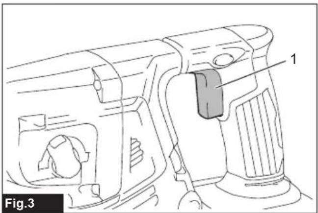
Switch action
⚠ WARNING: Before installing the battery cartridge into the tool, always check to see that the switch trigger actuates properly and returns to the "OFF" position when released.
▶ Fig.3: 1. Switch trigger
To start the tool, simply pull the switch trigger. Tool speed is increased by increasing pressure on the switch trigger. Release the switch trigger to stop.
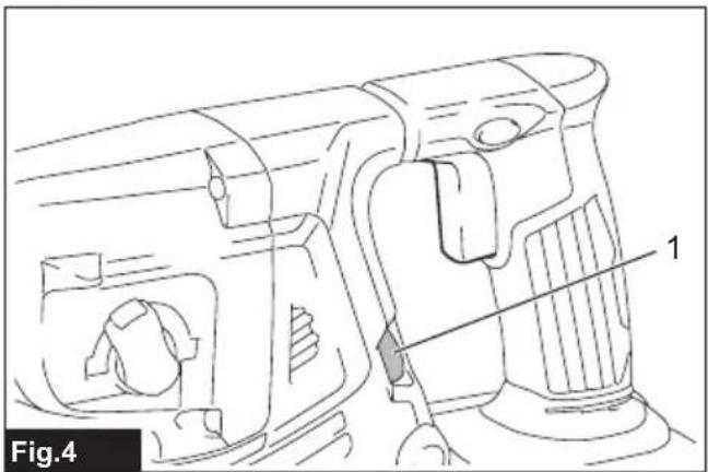
Speed change
The revolutions and blows per minute can be adjusted by turning the adjusting dial. The dial is marked 1 (lowest speed) to 5 (full speed).
▶ Fig.4: 1. Adjusting dial
Refer to the table below for the relationship between the number on the adjusting dial and the revolutions and
blows per minute.
| Number Revolutions per minute | Blows per minute |
| 5 980 5,000 | |
| 4 810 4,130 | |
| 3 640 3,260 | |
| 2 470 2,400 | |
| 1 300 1,550 |
CAUTION: Do not turn the adjusting dial when the tool is running. Failure to do so may result in the loss of control of the tool and cause an injury.
NOTICE: If the tool is operated continuously at low speed for a long time, the motor will get overloaded, resulting in tool malfunction.
NOTICE: The speed adjusting dial can be turned only as far as 5 and back to 1. Do not force it past 5 or 1, or the speed adjusting function may no longer work.
NOTE: Soft no-load rotation function (For DHR282/DHR283)
When the speed adjusting dial is set to "3" or higher, the tool automatically reduces the speed at no-load to reduce the vibration under no-load. Once operation starts with a bit against concrete, blows per minute increase and reach the numbers as shown in the table. When temperature is low and there is less fluidity in grease, the tool may not have this function even with the motor rotating.
This function is not available when the dust collection system is installed.
Lighting up the front lamp
▶ Fig.5: 1. Lamp
CAUTION: Do not look in the light or see the source of light directly.
Pull the switch trigger to light up the lamp. The lamp keeps on lighting while the switch trigger is being pulled. The lamp goes out approximately 10 seconds after releasing the switch trigger.
If the lamp goes off after blinking for a few seconds, the active feedback sensing technology or the soft no-load rotation function is not working properly. Ask your local Makita Service Center for repair.
NOTE: Use a dry cloth to wipe the dirt off the lens of the lamp. Be careful not to scratch the lens of the lamp, or it may lower the illumination.
NOTE: If the dust collection system is installed on the tool, the lamp of the dust collection system lights up instead of the lamp of the tool.
Reversing switch action
▶ Fig.6: 1. Reversing switch lever
⚠️CAUTION: Always check the direction of rotation before operation.
⚠️CAUTION: Use the reversing switch only after the tool comes to a complete stop. Changing the direction of rotation before the tool stops may damage the tool.
⚠️CAUTION: When not operating the tool, always set the reversing switch lever to the neutral position.
This tool has a reversing switch to change the direction of rotation. Depress the reversing switch lever from the A side for clockwise rotation or from the B side for counterclockwise rotation.
When the reversing switch lever is in the neutral position, the switch trigger cannot be pulled.
Changing the quick change chuck for SDS-plus
For DHR281/DHR283
The quick change chuck for SDS-plus can be easily exchanged for the quick change drill chuck.
Removing the quick change chuck for SDS-plus
⚠️CAUTION: Before removing the quick change chuck for SDS-plus, be sure to remove the bit.
Grasp the change cover of the quick change chuck for SDS-plus and turn in the direction of the arrow until the change cover line moves from the symbol to the symbol. Pull forcefully in the direction of the arrow.
▶ Fig.7: 1. Quick change chuck for SDS-plus 2. Change cover 3. Change cover line
Installing the quick change drill chuck
Check the line of the quick change drill chuck shows the symbol. Grasp the change cover of the quick change drill chuck and set the line to the symbol. Place the quick change drill chuck on the spindle of the tool. Grasp the change cover of the quick change drill chuck and turn the change cover line to the symbol until a click can clearly be heard.
▶ Fig.8: 1. Quick change drill chuck 2. Spindle 3. Change cover line 4. Change cover
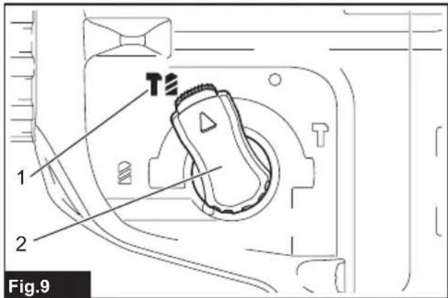
Selecting the action mode
NOTICE: Do not rotate the action mode changing knob when the tool is running. The tool will be damaged.
NOTICE: To avoid rapid wear on the mode change mechanism, be sure that the action mode changing knob is always positively located in one of the three action mode positions.
Rotation with hammering
For drilling in concrete, masonry, etc., rotate the action mode changing knob to the symbol. Use a tungsten-carbide tipped bit (optional accessory).
▶ Fig.9: 1. Rotation with hammering 2. Action mode changing knob
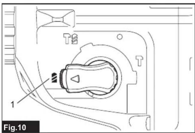
Rotation only
For drilling in wood, metal or plastic materials, rotate the action mode changing knob to the symbol. Use a twist drill bit or wood drill bit.
▶ Fig.10: 1. Rotation only
Hammering only
For chipping, scaling or demolition operations, rotate the action mode changing knob to the symbol. Use a bull point, cold chisel, scaling chisel, etc.
▶ Fig.11: 1. Hammering only
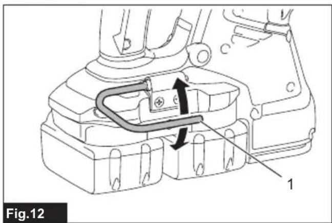
Hook
CAUTION: Never hook the tool at high location or on potentially unstable surface.
▶ Fig.12: 1. Hook
The hook is convenient for temporarily hanging the tool. To use the hook, simply lift up hook until it snaps into the open position. When not in use, always lower hook until it snaps into the closed position.
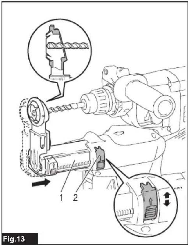
Adjusting the nozzle position of the dust collection system
Optional accessory
Push in the guide while pushing up the guide adjustment button, and then release the button at the desired position.
▶ Fig.13: 1. Guide 2. Guide adjustment button
NOTE: Before adjusting the nozzle position, release the nozzle forward completely by pushing up the guide adjustment button.
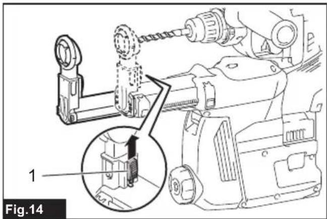
If a long drill bit is installed, extend the guide by pushing up the extension button.
▶ Fig.14: 1. Extension button
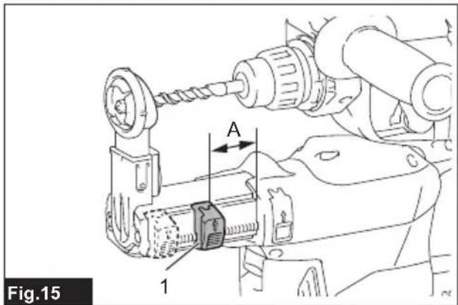
Adjusting the drilling depth of the dust collection system
Optional accessory
Slide the depth adjustment button to the desired position while pushing it up. The distance (A) is the drilling depth.
▶ Fig.15: 1. Depth adjustment button
Torque limiter
NOTICE: As soon as the torque limiter actuates, switch off the tool immediately. This will help prevent premature wear of the tool.
NOTICE: Drill bits such as hole saw, which tend to pinch or catch easily in the hole, are not appropriate for this tool. This is because they will cause the torque limiter to actuate too frequently.
The torque limiter will actuate when a certain torque level is reached. The motor will disengage from the output shaft. When this happens, the drill bit will stop turning.
Electronic function
The tool is equipped with the electronic functions for easy operation.
- Constant speed control
The speed control function provides the constant rotation speed regardless of load conditions.
• Active Feedback sensing Technology (For DHR282/DHR283)
If the tool is swung at the predetermined acceleration during operation, the motor is forcibly stopped to reduce the burden on the wrist.
NOTE: This function does not work if the acceleration does not reach the predetermined one when the tool is swung.
NOTE: If the bit is swung at the predetermined acceleration during chipping, scaling, or demolishing, the motor is forcibly stopped. In this case, release the switch trigger, and then pull the switch trigger to restart the tool.
ASSEMBLY
⚠️CAUTION: Always be sure that the tool is switched off and the battery cartridge is removed before carrying out any work on the tool.
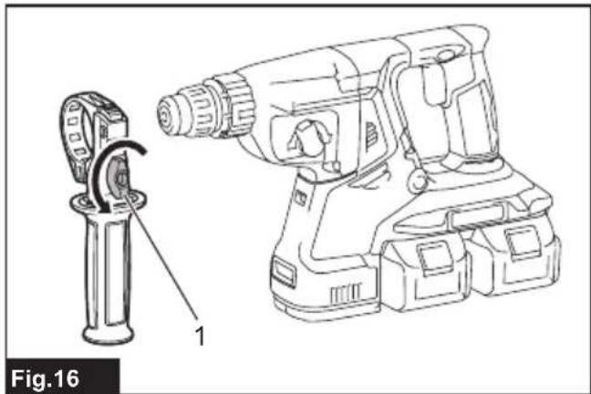
Side grip (auxiliary handle)
⚠️CAUTION: Always use the side grip to ensure safe operation.
⚠️CAUTION: After installing or adjusting the side grip, make sure that the side grip is firmly secured.
- Loosen the thumb screw on the side grip.
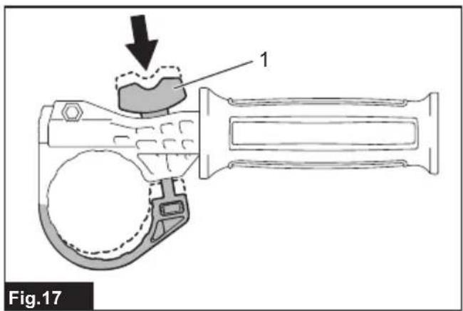
▶ Fig.16: 1. Thumb screw - Attach the side grip while pressing the thumb screw so that the grooves on the grip fit in the protrusions on the tool barrel.
▶ Fig.17: 1. Thumb screw - Tighten the thumb screw to secure the grip. The grip can be fixed at desired angle.
Grease
Coat the shank end of the drill bit beforehand with a small amount of grease (about 0.5 - 1 g).
This chuck lubrication assures smooth action and longer service life.
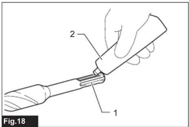
Installing or removing drill bit
Clean the shank end of the drill bit and apply grease before installing the drill bit.
▶ Fig.18: 1. Shank end 2. Grease
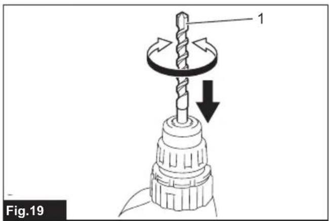
Insert the drill bit into the tool. Turn the drill bit and push it in until it engages.
After installing the drill bit, always make sure that the drill bit is securely held in place by trying to pull it out.
▶ Fig.19: 1. Drill bit
To remove the drill bit, pull the chuck cover down all the way and pull the drill bit out.
▶ Fig.20: 1. Drill bit 2. Chuck cover
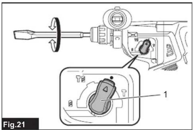
Chisel angle (when chipping, scaling or demolishing)
The chisel can be secured at the desired angle. To change the chisel angle, rotate the action mode changing knob to the O symbol. Turn the chisel to the desired angle.
▶ Fig.21: 1. Action mode changing knob
Rotate the action mode changing knob to the symbol. Then make sure that the chisel is securely held in place by turning it slightly.
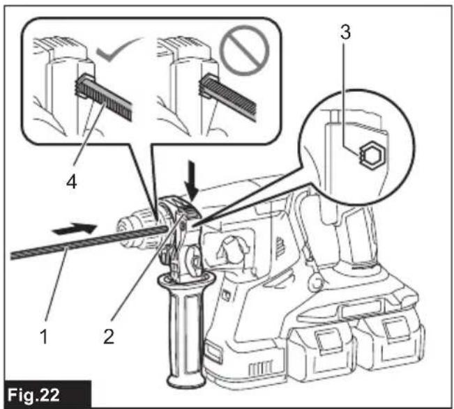
Depth gauge
The depth gauge is convenient for drilling holes of uniform depth.
Press and hold the lock button, and then insert the depth gauge into the hex hole. Make sure that the toothed side of the depth gauge faces the marking.
▶ Fig.22: 1. Depth gauge 2. Lock button 3. Marking 4. Toothed side
Adjust the depth gauge by moving it back and forth while pressing the lock button. After the adjustment, release the lock button to lock the depth gauge.
NOTE: Make sure that the depth gauge does not touch the main body of the tool when attaching it.
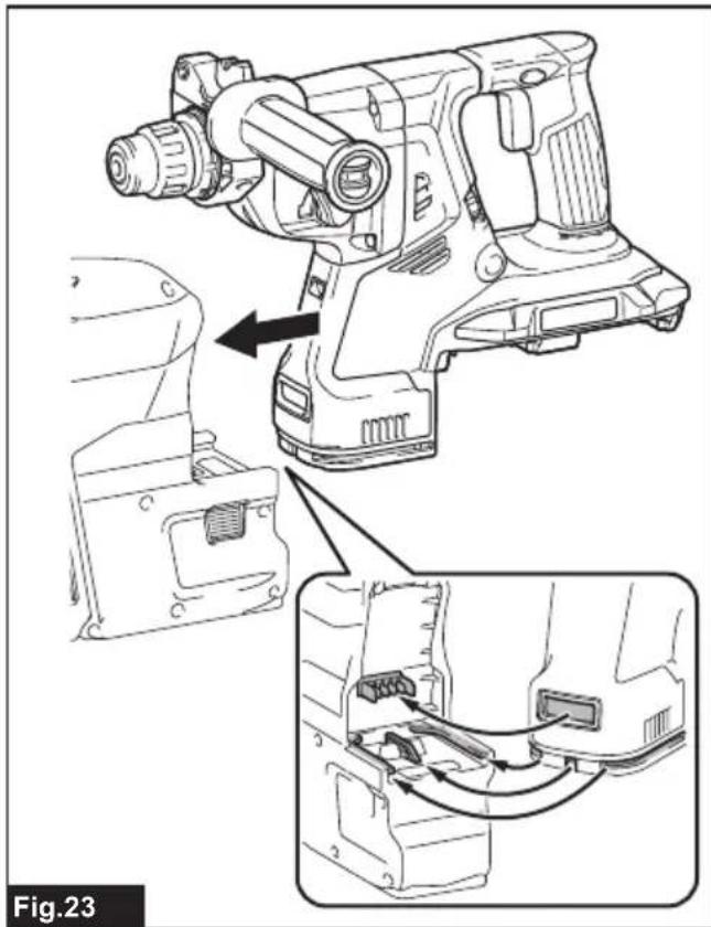
Installing or removing the dust collection system
Optional accessory
To install the dust collection system, insert the tool into the dust collection system all the way until it locks in place with a little double click.
▶ Fig.23
To remove the dust collection system, pull the tool while pressing the lock-off button.
▶ Fig.24: 1. Lock-off button
Dust cup
Optional accessory
Use the dust cup to prevent dust from falling over the tool and on yourself when performing overhead drilling operations. Attach the dust cup to the bit as shown in the figure. The size of bits which the dust cup can be attached to is as follows.
| Model Bit diameter | |
| Dust cup 5 6 mm - 14.5 mm | |
| Dust cup 9 12 mm - 16 mm |
▶ Fig.25: 1. Dust cup
Dust cup set
Optional accessory
Before installing the dust cup set, remove the bit from the tool if installed.
Install the dust cup set on the tool so that the △ symbol on the dust cup is aligned with the groove in the tool.
▶ Fig.26: 1. △ symbol 2. Groove
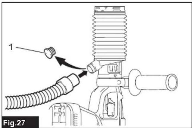
NOTE: If you connect a vacuum cleaner to the dust cup set, remove the dust cap before connecting it.
▶ Fig.27: 1. Dust cap
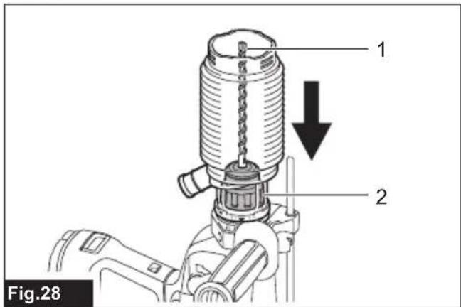
To remove the dust cup set, remove the bit while pulling the chuck cover in the direction of the arrow.
▶ Fig.28: 1. Bit 2. Chuck cover
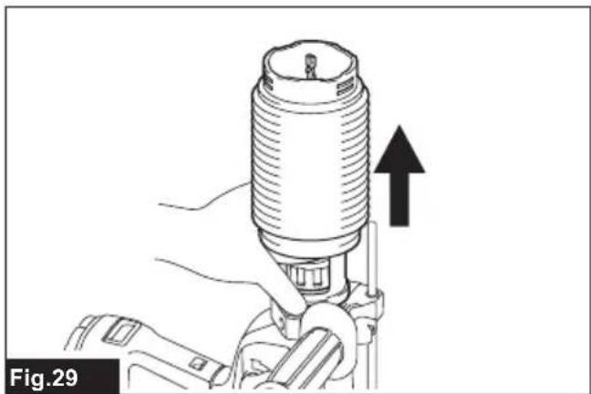
Hold the root of dust cup and pull it out.
▶ Fig.29
NOTE: If the cap comes off from the dust cup, attach it with its printed side facing up so that groove on the cap fits in the inside periphery of the attachment.
▶ Fig.30
OPERATION
CAUTION: Always use the side grip (auxiliary handle) and firmly hold the tool by both side grip and switch handle during operations.
CAUTION: Always make sure that the workpiece is secured before operation.
CAUTION: Do not pull the tool out forcibly even the bit gets stuck. Loss of control may cause injury.
CAUTION: The dust collection system is intended for drilling in concrete only. Do not use the dust collection system for drilling in metal or wood.
CAUTION: When using the tool with the dust collection system, be sure to attach the filter to the dust collection system to prevent dust inhalation.
CAUTION: Before using the dust collection system, check that the filter is not damaged. Failure to do so may cause dust inhalation.
CAUTION: The dust collection system collects the generated dust at a considerable rate, but not all dust can be collected.
NOTICE: Do not use the dust collection system for core drilling or chiseling.
NOTICE: Do not use the dust collection system for drilling in wet concrete or use this system in wet environment. Failure to do so may cause malfunction.
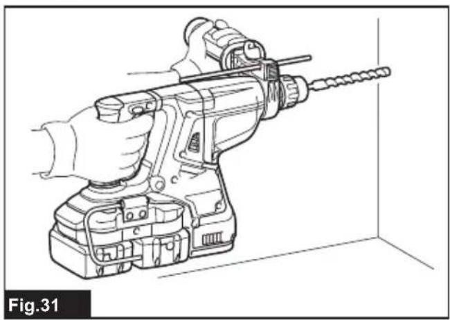
NOTE: If the battery cartridge is in low temperature, the tool's capability may not be fully obtained. In this case, warm up the battery cartridge by using the tool with no load for a while to fully obtain the tool's capability.
▶ Fig.31
Hammer drilling operation
CAUTION: There is tremendous and sudden twisting force exerted on the tool/drill bit at the time of hole break-through, when the hole becomes clogged with chips and particles, or when striking reinforcing rods embedded in the concrete. Always use the side grip (auxiliary handle) and firmly hold the tool by both side grip and switch handle during operations. Failure to do so may result in the loss of control of the tool and potentially severe injury.
Set the action mode changing knob to the symbol. Position the drill bit at the desired location for the hole, then pull the switch trigger. Do not force the tool. Light pressure gives best results. Keep the tool in position and prevent it from slipping away from the hole.
Do not apply more pressure when the hole becomes clogged with chips or particles. Instead, run the tool at an idle, then remove the drill bit partially from the hole. By repeating this several times, the hole will be cleaned
out and normal drilling may be resumed.
NOTE: Eccentricity in the drill bit rotation may occur while operating the tool with no load. The tool automatically centers itself during operation. This does not affect the drilling precision.
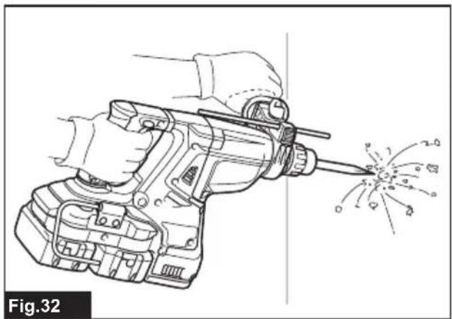
Chipping/Scaling/Demolition
Set the action mode changing knob to the symbol. Hold the tool firmly with both hands. Turn the tool on and apply slight pressure on the tool so that the tool will not bounce around, uncontrolled.
Pressing very hard on the tool will not increase the efficiency.
▶ Fig.32
Drilling in wood or metal
⚠️CAUTION: Hold the tool firmly and exert care when the drill bit begins to break through the workpiece. There is a tremendous force exerted on the tool/drill bit at the time of hole break through.
⚠CAUTION: A stuck drill bit can be removed simply by setting the reversing switch to reverse rotation in order to back out. However, the tool may back out abruptly if you do not hold it firmly.
⚠️CAUTION: Always secure workpieces in a vise or similar hold-down device.
NOTICE: Never use "rotation with hammering" when the drill chuck is installed on the tool. The drill chuck may be damaged.
Also, the drill chuck will come off when reversing the tool.
NOTICE: Pressing excessively on the tool will not speed up the drilling. In fact, this excessive pressure will only serve to damage the tip of your drill bit, decrease the tool performance and shorten the service life of the tool.
Set the action mode changing knob to the symbol.
For DHR280/DHR282
Optional accessory
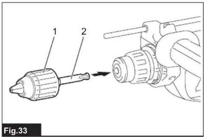
Attach the chuck adapter to a keyless drill chuck to which 1/2"-20 size screw can be installed, and then install them to the tool. When installing it, refer to the section "Installing or removing drill bit".
▶ Fig.33: 1. Keyless drill chuck 2. Chuck adapter
For DHR281/DHR283
Use the quick change drill chuck as standard equipment. When installing it, refer to "changing the quick change chuck for SDS-plus".
Hold the ring and turn the sleeve counterclockwise to open the chuck jaws. Place the bit in the chuck as far as it will go. Hold the ring firmly and turn the sleeve clockwise to tighten the chuck.
▶ Fig.34: 1. Sleeve 2. Ring
To remove the bit, hold the ring and turn the sleeve counterclockwise.
Diamond core drilling
NOTICE: If performing diamond core drilling operations using “rotation with hammering” action, the diamond core bit may be damaged.
When performing diamond core drilling operations, always set the action mode changing knob to the position to use "rotation only" action.
Beating dust on the filter
Optional accessory
CAUTION: Do not turn the dial on the dust case while the dust case is removed from the dust collection system. Doing so may cause dust inhalation.
CAUTION: Always switch off the tool when turning the dial on the dust case. Turning the dial while the tool is running may result in the loss of control of the tool.
By beating the dust on the filter inside the dust case, you can keep the vacuum efficiency and also reduce the number of times to dispose of the dust.
Turn the dial on the dust case three times after collecting every 50,000 mm ^3 of dust or when you feel the vacuum performance declined.
NOTE: 50,000 mm ^3 of dust equivalents to drilling 10 holes of 10 mm and 65 mm depth (14 holes of 3/8" and 2" depth).
▶ Fig.35: 1. Dust case 2. Dial
Disposing of dust
Optional accessory
CAUTION: Always be sure that the tool is switched off and the battery cartridge is removed before carrying out any work on the tool.
⚠️ CAUTION: Be sure to wear dust mask when disposing of dust.
⚠️ CAUTION: Empty the dust case regularly before the dust case becomes full. Failure to do so may decrease the dust collection performance and cause dust inhalation.
⚠️ CAUTION: The performance of dust collection decreases if the filter in the dust case become clogged. Replace the filter with new one after approximately 200 times of dust fulfillment as a guide. Failure to do so may cause dust inhalation.
- Remove the dust case while pressing down the lever of the dust case.
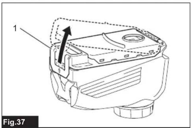
▶ Fig.36: 1. Lever - Open the cover of the dust case.
▶ Fig.37: 1. Cover - Dispose of the dust, and then clean the filter.
▶ Fig.38
NOTICE: When cleaning the filter, tap the case of the filter gently by hand to remove dust. Do not tap the filter directly; touch the filter with brush or similar; or blow compressed air on the filter. Doing so may damage the filter.
Blow-out bulb
Optional accessory
After drilling the hole, use the blow-out bulb to clean the dust out of the hole.
▶ Fig.39
Using dust cup set
Optional accessory
Fit the dust cup set against the ceiling when operating the tool.
▶ Fig.40
NOTICE: Do not use the dust cup set when drilling in metal or similar. It may damage the dust cup set due to the heat produced by small metal dust or similar.
NOTICE: Do not install or remove the dust cup set with the drill bit installed in the tool. It may damage the dust cup set and cause dust leak.
WIRELESS ACTIVATION FUNCTION
Optional accessory for DHR282/DHR283
What you can do with the wireless activation function
The wireless activation function enables clean and comfortable operation. By connecting a supported vacuum cleaner to the tool, you can run the vacuum cleaner automatically along with the switch operation of the tool.
▶ Fig.41
To use the wireless activation function, prepare following items:
- A wireless unit (optional accessory)
- A vacuum cleaner which supports the wireless activation function
The overview of the wireless activation function setting is as follows. Refer to each section for detail procedures.
- Installing the wireless unit
- Tool registration for the vacuum cleaner
- Starting the wireless activation function
Installing the wireless unit
Optional accessory
⚠️ CAUTION: Place the tool on a flat and stable surface when installing the wireless unit.
NOTICE: Clean the dust and dirt on the tool before installing the wireless unit. Dust or dirt may cause malfunction if it comes into the slot of the wireless unit.
NOTICE: To prevent the malfunction caused by static, touch a static discharging material, such as a metal part of the tool, before picking up the wireless unit.
NOTICE: When installing the wireless unit, always be sure that the wireless unit is inserted in the correct direction and the lid is completely closed.
- Open the lid on the tool as shown in the figure.
▶ Fig.42: 1. Lid - Insert the wireless unit to the slot and then close the lid.
When inserting the wireless unit, align the projections with the recessed portions on the slot.
▶ Fig.43: 1. Wireless unit 2. Projection 3. Lid 4. Recessed portion
When removing the wireless unit, open the lid slowly.
The hooks on the back of the lid will lift the wireless unit as you pull up the lid.
▶ Fig.44: 1. Wireless unit 2. Hook 3. Lid
After removing the wireless unit, keep it in the supplied case or a static-free container.
NOTICE: Always use the hooks on the back of the lid when removing the wireless unit. If the hooks do not catch the wireless unit, close the lid completely and open it slowly again.
Tool registration for the vacuum cleaner
NOTE: A Makita vacuum cleaner supporting the wireless activation function is required for the tool registration.
NOTE: Finish installing the wireless unit to the tool before starting the tool registration.
NOTE: During the tool registration, do not pull the switch trigger or turn on the power switch on the vacuum cleaner.
NOTE: Refer to the instruction manual of the vacuum cleaner, too.
If you wish to activate the vacuum cleaner along with the switch operation of the tool, finish the tool registration beforehand.
- Install the batteries to the vacuum cleaner and the tool.
- Set the stand-by switch on the vacuum cleaner to "AUTO".
▶ Fig.45: 1. Stand-by switch
- Press the wireless activation button on the vacuum cleaner for 3 seconds until the wireless activation lamp blinks in green. And then press the wireless activation button on the tool in the same way.
▶ Fig.46: 1. Wireless activation button 2. Wireless activation lamp
If the vacuum cleaner and the tool are linked successfully, the wireless activation lamps will light up in green for 2 seconds and start blinking in blue.
NOTE: The wireless activation lamps finish blinking in green after 20 seconds elapsed. Press the wireless activation button on the tool while the wireless activation lamp on the cleaner is blinking. If the wireless activation lamp does not blink in green, push the wireless activation button briefly and hold it down again.
NOTE: When performing two or more tool registrations for one vacuum cleaner, finish the tool registration one by one.
Starting the wireless activation function
NOTE: Finish the tool registration for the vacuum cleaner prior to the wireless activation.
NOTE: Refer to the instruction manual of the vacuum cleaner, too.
After registering a tool to the vacuum cleaner, the vacuum cleaner will automatically run along with the switch operation of the tool.
-
Install the wireless unit to the tool.
-
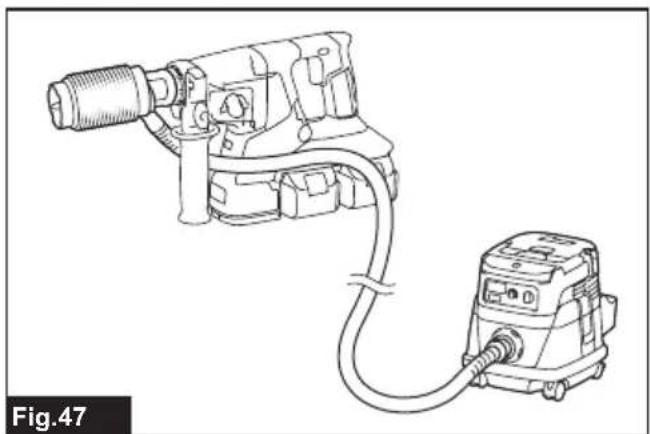
Connect the hose of the vacuum cleaner with the tool.
▶ Fig.47
- Set the stand-by switch on the vacuum cleaner to "AUTO".
▶ Fig.48: 1. Stand-by switch
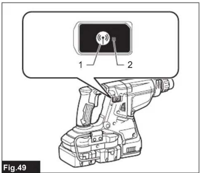
- Push the wireless activation button on the tool briefly. The wireless activation lamp will blink in blue.
▶ Fig.49: 1. Wireless activation button 2. Wireless activation lamp
- Turn on the tool. Check if the vacuum cleaner runs while the tool is operating.
To stop the wireless activation of the vacuum cleaner, push the wireless activation button on the tool.
NOTE: The wireless activation lamp on the tool will stop blinking in blue when there is no operation for 2 hours. In this case, set the stand-by switch on the vacuum cleaner to "AUTO" and push the wireless activation button on the tool again.
NOTE: The vacuum cleaner starts/stops with a delay. There is a time lag when the vacuum cleaner detects a switch operation of the tool.
NOTE: The transmission distance of the wireless unit may vary depending on the location and surrounding circumstances.
NOTE: When two or more tools are registered to one vacuum cleaner, the vacuum cleaner may start running even if you do not turn on your tool because another user is using the wireless activation function.
Description of the wireless activation lamp status
▶ Fig.50: 1. Wireless activation lamp
The wireless activation lamp shows the status of the wireless activation function. Refer to the table below for the meaning of the lamp status.
| Status Wireless activation lamp Description | |||||
| Standby Blue | 2 hours The wireless activation of the vacuum cleaner is available. The lamp will automatically turn off when no operation is performed for 2 hours. | ||||
| When the tool is running. | The wireless activation of the vacuum cleaner is available and the tool is running. | ||||
| Tool registration | Green | 20 seconds Ready for the tool registration. Waiting for the registration by the vacuum cleaner. | |||
| 2 seconds The tool registration has been finished. The wireless activation lamp will start blinking in blue. | |||||
| Cancelling tool registration | Red | 20 seconds Ready for the cancellation of the tool registration. Waiting for the cancellation by the vacuum cleaner. | |||
| 2 seconds The cancellation of the tool registration has been finished. The wireless activation lamp will start blinking in blue. | |||||
| Others Red | 3 seconds The power is supplied to the wireless unit and the wireless activation function is starting up. | ||||
| Off | - | - | The wireless activation of the vacuum cleaner is stopped. | ||
Cancelling tool registration for the vacuum cleaner
Perform the following procedure when cancelling the tool registration for the vacuum cleaner.
-
Install the batteries to the vacuum cleaner and the tool.
-
Set the stand-by switch on the vacuum cleaner to "AUTO".
▶ Fig.51: 1. Stand-by switch
- Press the wireless activation button on the vacuum cleaner for 6 seconds. The wireless activation lamp blinks in green and then become red. After that,
press the wireless activation button on the tool in the same way.
▶ Fig.52: 1. Wireless activation button 2. Wireless activation lamp
If the cancellation is performed successfully, the wireless activation lamps will light up in red for 2 seconds and start blinking in blue.
NOTE: The wireless activation lamps finish blinking in red after 20 seconds elapsed. Press the wireless activation button on the tool while the wireless activation lamp on the cleaner is blinking. If the wireless activation lamp does not blink in red, push the wireless activation button briefly and hold it down again.
Troubleshooting for wireless activation function
Before asking for repairs, conduct your own inspection first. If you find a problem that is not explained in the manual, do not attempt to dismantle the tool. Instead, ask Makita Authorized Service Centers, always using Makita replacement parts for repairs.
| State of abnormality Probable cause | (malfunction) Remedy | |
| The wireless activation lamp does not light/blink. | The wireless unit is not installed into the tool.The wireless unit is improperly installed into the tool. | Install the wireless unit correctly. |
| The terminal of the wireless unit and/or the slot is dirty. | Gently wipe off dust and dirt on the terminal of the wireless unit and clean the slot. | |
| The wireless activation button on the tool has not been pushed. | Push the wireless activation button on the tool briefly. | |
| The stand-by switch on the vacuum cleaner is not set to "AUTO". | Set the stand-by switch on the vacuum cleaner to "AUTO". | |
| No power supply Supply the power to the tool and the vacuum cleaner. | ||
| Cannot finish tool registration / cancelling tool registration successfully. | The wireless unit is not installed into the tool.The wireless unit is improperly installed into the tool. | Install the wireless unit correctly. |
| The terminal of the wireless unit and/or the slot is dirty. | Gently wipe off dust and dirt on the terminal of the wireless unit and clean the slot. | |
| The stand-by switch on the vacuum cleaner is not set to "AUTO". | Set the stand-by switch on the vacuum cleaner to "AUTO". | |
| No power supply Supply the power to the tool and the vacuum cleaner. | ||
| Incorrect operation Push the wireless activation button briefly and perform the tool registration/cancellation procedures again. | ||
| The tool and vacuum cleaner are away from each other (out of the transmission range). | Get the tool and vacuum cleaner closer to each other. The maximum transmission distance is approximately 10 m however it may vary according to the circumstances. | |
| Before finishing the tool registration/cancellation;- the switch of the tool is turned on or;- the power button on the vacuum cleaner is turned on. | Push the wireless activation button briefly and perform the tool registration/cancellation procedures again. | |
| The tool registration procedures for the tool or vacuum cleaner have not finished. | Perform the tool registration procedures for both the tool and the vacuum cleaner at the same timing. | |
| Radio disturbance by other appliances which generate high-intensity radio waves. | Keep the tool and vacuum cleaner away from the appliances such as Wi-Fi devices and microwave ovens. | |
| The vacuum cleaner does not run along with the switch operation of the tool. | The wireless unit is not installed into the tool.The wireless unit is improperly installed into the tool. | Install the wireless unit correctly. |
| The terminal of the wireless unit and/or the slot is dirty. | Gently wipe off dust and dirt on the terminal of the wireless unit and clean the slot. | |
| The wireless activation button on the tool has not been pushed. | Push the wireless activation button briefly and make sure that the wireless activation lamp is blinking in blue. | |
| The stand-by switch on the vacuum cleaner is not set to "AUTO". | Set the stand-by switch on the vacuum cleaner to "AUTO". | |
| More than 10 tools are registered to the vacuum cleaner. | Perform the tool registration again.If more than 10 tools are registered to the vacuum cleaner, the tool registered earliest will be cancelled automatically. | |
| The vacuum cleaner erased all tool registrations. | Perform the tool registration again. | |
| No power supply Supply the power to the | tool and the vacuum cleaner. | |
| The tool and vacuum cleaner are away from each other (out of the transmission range). | Get the tool and vacuum cleaner closer each other.The maximum transmission distance is approximately 10 m however it may vary according to the circumstances. | |
| Radio disturbance by other appliances which generate high-intensity radio waves. | Keep the tool and vacuum cleaner away from the appliances such as Wi-Fi devices and microwave ovens. | |
| The vacuum cleaner runs while the tool is not operating. | Other users are using the wireless activation of the vacuum cleaner with their tools. | Turn off the wireless activation button of the other tools or cancel the tool registration of the other tools. |
MAINTENANCE
⚠️CAUTION: Always be sure that the tool is switched off and the battery cartridge is removed before attempting to perform inspection or maintenance.
NOTICE: Never use gasoline, benzine, thinner, alcohol or the like. Discoloration, deformation or cracks may result.
To maintain product SAFETY and RELIABILITY, repairs, any other maintenance or adjustment should be performed by Makita Authorized or Factory Service Centers, always using Makita replacement parts.
Replacing filter of dust case
Optional accessory
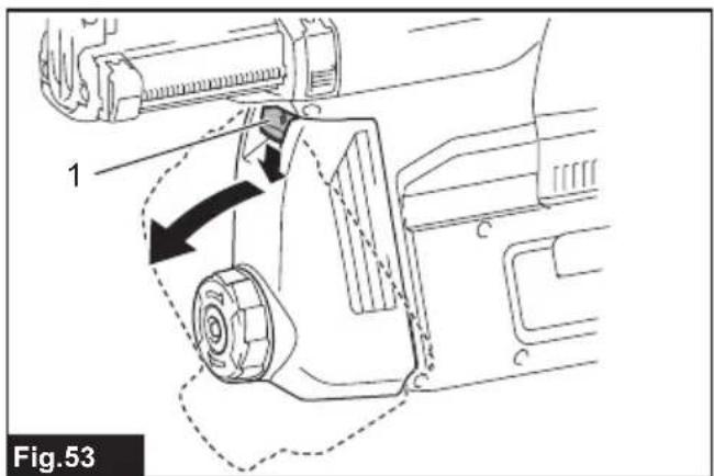
- Remove the dust case while pressing down the lever of the dust case.
▶ Fig.53: 1. Lever
- Insert the flat-blade screwdriver into the slots of the filter cover to remove the filter cover.
▶ Fig.54: 1. Flat-blade screwdriver 2. Filter cover
- Remove the filter from the filter case.
▶ Fig.55: 1. Filter 2. Filter case
-
Attach a new filter to the filter case, and then attach the filter cover.
-
Close the cover of the dust case, and then attach
the dust case to the dust collection system.
Replacing sealing cap
Optional accessory
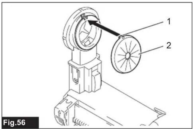
If the sealing cap is worn out, the performance of the dust collection decreases. Replace it if it's worn out. Remove the sealing cap, and then attach a new one with its protrusion facing upward.
▶ Fig.56: 1. Protrusion 2. Sealing cap
OPTIONAL ACCESSORIES
CAUTION: These accessories or attachments are recommended for use with your Makita tool specified in this manual. The use of any other accessories or attachments might present a risk of injury to persons. Only use accessory or attachment for its stated purpose.
If you need any assistance for more details regarding these accessories, ask your local Makita Service Center.
- Carbide-tipped drill bits (SDS-Plus carbide-tipped bits)
- Core bit
- Bull point
-
Diamond core bit
-
Cold chisel
- Scaling chisel
- Grooving chisel
- Chuck adapter
• Keyless drill chuck - Bit grease
- Depth gauge
- Blow-out bulb
- Dust cup
- Dust cup set
- Dust collection system
- Wireless unit
- Plastic carrying case
- Makita genuine battery and charger
NOTE: Some items in the list may be included in the tool package as standard accessories. They may differ from country to country.
SPÉCIFICATIONS
▶ Fig.34: 1. Manchon 2. Bague
▶ Abb.26: 1. △ Symbol 2. Nut
▶ Abb.33: 1. Schlüsselloses Bohrfutter 2. Futteradapter
Für DHR281/DHR283
⚠ WAARSCHUWING: Draag gehoorbescherming.
VEILIGHEIDSWAAR- SCHUWINGEN
▶ Fig.14: 1. Uitschuifknop
▶ Fig.25: 1. Stofvanger
Stofvangerset
Optioneel accessoire
▶ Fig.34: 1. Bus 2. Ring
▶ Fig.35: 1. Stofopvangdoos 2. Knop
Het stof weggooien
Optioneel accessoire
OPTIONELE ACCESSOIRES
▶ Fig.28: 1. Broca 2. Tampa do mandril
▶ Fig.34: 1. Muffe 2. Ring
▶ Eik.42: 1. Kappáki