
KA220E - Sander BLACK & DECKER - Free user manual and instructions
Find the device manual for free KA220E BLACK & DECKER in PDF.

| Brand | Black & Decker |
| Model | KA220E |
| Product type | Multi-sander (eccentric and orbital) |
| Power supply | Mains 230 V, 50 Hz |
| Power | 250 W (estimated) |
| Variable speed | Yes, with electronic speed control |
| Included pads | Round, pointed, for profiles |
| Orbital stroke | Orbital + rotary motion (eccentric mode) |
| Dust extraction system | Integrated dust bag |
| Auto-locking system (ABS) | Yes, maintains speed when idling |
| Double insulation | Yes, no earth connection required |
| Side handle | Yes, adjustable |
| Sound level | Sound pressure 77.1 dB(A), sound power 90.1 dB(A) |
| Hand-arm vibrations | < 2.5 m/s² |
| Weight | Approximately 1.5 kg |
| Dimensions (L × W × H) | Approximately 25 × 15 × 12 cm |
| Maintenance | Empty the bag every 10 minutes, do not wash the bag |
| Safety | Safety rules for sanding lead paint, double insulation |
| Spare parts | Pads, abrasive papers, points, dust bag, dust extraction adapter |
| Warranty | 2 years parts and labor |
Frequently Asked Questions - KA220E BLACK & DECKER
User questions about KA220E BLACK & DECKER
0 question about this device. Answer the ones you know or ask your own.
Ask a new question about this device
Download the instructions for your Sander in PDF format for free! Find your manual KA220E - BLACK & DECKER and take your electronic device back in hand. On this page are published all the documents necessary for the use of your device. KA220E by BLACK & DECKER.
USER MANUAL KA220E BLACK & DECKER
natural_image
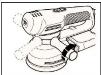
Line drawing of a power tool with a base and disc assembly (no text or symbols)KA200
KA210
KA220
KA230
| Australia DeWalt Industrial Power Tool Company (Distributors of Tel: 03 9895 9200Black & Decker products), 7 Clarice Road, Box Hill, Victoria 3128 Fax: 03 9899 7465 | ||
| Belgique/België Black & Decker Belgium NV Tel: 02 719 07 11Weihoek 1, 1930 Zaventem Fax: 02 721 40 45 | ||
| Danmark Black & Decker Tlf: 70-20 15 10Hejrevang 26 B, 3450 Allerød Fax: 48-14 13 99 | ||
| Deutschland Black & Decker GmbH Tel: 06126 210Black & Decker Straße 40, 65510 Idstein Fax: 06126 212601 | ||
| Ελλάς | Black & Decker (Ελλάς) AEΛεωφ. Συγγρού 154Αθήνα 176 71 | Τηλ: 01 9242870-75Service: 01 9242876-7Fax: 01 9242869 |
| España | Black & Decker de España SACtra. de Acceso a Roda de Bará, km 0,743883-Roda de Bará, Tarragona | Tel: 977 297100Tlx: 56631 BLADE EFax: 977 299139 |
| France | Black & Decker (France) SarlLe Paisy69570 Dardilly, Lyon | Tel: 04 72 20 39 20Tlx: 300 250Fax: 04 72 20 39 00 |
| Helvetia | Black & Decker AG ElektrowerkzeugeRütistraße 14, CH-8952 SchlierenSchweiz/Suisse | Tel: 01 730 69 33Tlx: 54462 BDZH CHFax: 01 730 70 67 |
| Italia | Black & Decker Italia SpAViale Elvezia 2, 20052 Monza (Mi) | Tel: 039 23 87 1Fax: 039 23 87 59 3Numero verde: 167 21 39 35 |
| Maroc | Ets Louis Guillard & Cie31, Rue Pierre Parent, Casablanca | Tel: 02-30 59 71Fax: 02-31 78 88E-mail: elg@mail.sis.net.ma |
| Nederland | Black & Decker (Nederland) BVFlorijnstraat 10, 4879 AH Etten-Leur | Tel: 076 5082000Fax: 076 5038184 |
| New Zealand | Black & Decker483 Great South Road, Penrose, Auckland | Tel: 09 579 7600Fax: 09 579 8200 |
| Norge | Black & Decker (Norge) A/S Tel: 22-90 99 00Strømsveien 344, 1081 Oslo | Fax: 22-90 99 01 |
| Österreich | Black & DeckerWerkzeugevertriebs GmbHErlaaerstraße 165, Postfach 69, 1230 Wien | Tel: 0222 66 116 0Tlx: 13228 BLACK AFax: 0222 66 116 14 |
| Portugal | Black & DeckerRua Egas Moniz 173, Apartado 19S. João do Estoril, 2768 Estoril, Codex | Tel: 468 76 13/468 75 13Tlx: 16 607 BLADEC PFax: 467 15 80 |
| South Africa | Black & Decker South Africa (Pty) LtdSuite no 107, PostNet X65, Halfway House 1685 | Tel: 011 314 4431Fax: 011 314 4435 |
| Suomi | Black & Decker OyRälssitie 7 C, 01510 Vantaa | Puh: 09-825 45 40Fax: 09-825 45 444 |
| Frälsevägen 7 C01510 Vanda | Tel: 09-825 45 40Fax: 09-825 45 444 | |
| Sverige | Black & Decker ABBox 603, 421 26 Västra Frölunda, Besöksadr. Ekonomivägen 11 | Tel: 031-68 60 00Fax: 031-68 60 08 |
| Tunis | Brico-Center60, Rue du 18 Janvier, 1001 Tunis | Tel: 01-242 856/334 826Fax: 01-330 136/353 699 |
| Türkiye | Black & Decker Elektrikli Ev (Aletleri Türkiye Distribütörü):Vestel Dayanıklı Tüketim, Malları Paz. A.Ş., Eski BüyükdereCad. İETT Garajı Yanı, 80650 4. Levent - İstanbul | Tel: 0 212 282 3600 (10 hat)Fax: 0 212 282 3307 |
| United Kingdom | Black & Decker210 Bath Road, Slough Tlx: 848317 BAND MHBerkshire SL1 3YD | Tel: 01753 574277Fax: 01753 551155 |
KÆRE KUNDE,
On the purchase of your Black & Decker product.
To ensure the best results from your power tool please read these safety and usage instructions carefully. If you have any questions or queries after reading this user manual please do not hesitate to call our Service and Information Centre, whose number you will find towards the back of this user manual, or one of our Authorised Repair Agents. A list of these Agents and further information is available on the Internet at www.2helpU.com.
¡ENHORABUENA!
natural_image
Hand pressing a button on a circular component (no text or symbols visible)HASTIGHEDSREGULATOR (KA210E/KA220E/KA230E)
natural_image
Diagram of a hand pressing down on a curved mechanical component with directional arrows (no text or symbols)natural_image
Illustration of a hand using a power tool on a circular base with directional arrows indicating rotation (no text or symbols)natural_image
Mechanical assembly diagram showing a gear and wheel assembly (no text or labels)natural_image
Line drawing of a mechanical device with a circular top component and central hub (no text or symbols)natural_image
Mechanical assembly diagram showing a device with gears and a lever (no text or symbols)natural_image
Technical line drawing of a mechanical device with rotating components and directional arrows indicating motion (no text or symbols)natural_image
Line drawing of a mechanical device with granular material and a circular component (no text or symbols)natural_image
Mechanical assembly diagram showing a clamping mechanism with no visible text or symbolsnatural_image
Technical illustration showing two mechanical clamping steps with arrows indicating motion direction (no text or symbols)natural_image
Diagram of a mechanical device with a roller and directional arrows indicating motion (no text or symbols)natural_image
Technical line drawing of a mechanical assembly with no visible text or symbolsnatural_image
Line drawing of a handheld industrial power shaver with lever mechanism (no text or symbols)T∅MNING AF ST∅VPOSEN
natural_image
Diagram showing a hand holding a device with arrows indicating motion or force (no text or symbols present)natural_image
Three-step line drawing showing hands using a power tool to adjust a circular component (no text or symbols present)Brian Cooke - Director of Engineering
Black & Decker, Spennymoor, Co Durham DL16 6JG, UK
natural_image
Hand pressing a button on a circular component (no text or symbols visible)natural_image
Illustration of a hand pressing down on a curved mechanical component with directional arrows (no text or symbols)(KA200/KA220/KA220E/KA230E)
natural_image
Illustration of a hand using a power tool on a circular workpiece with directional arrows (no text or symbols)natural_image
Technical diagram of a mechanical assembly with no visible text or symbolsnatural_image
Line drawing of a mechanical device with a circular component on top (no text or symbols)natural_image
Mechanical assembly diagram showing a device with gears and a lever, no text or symbols presentnatural_image
Technical diagram of a mechanical device with directional arrows indicating motion or flow (no text or symbols)natural_image
Line drawing of a mechanical device with textured surfaces and a central circular component (no text or symbols)natural_image
Mechanical assembly diagram showing a clamping mechanism with no visible text or symbolsnatural_image
Technical illustration showing two mechanical clamping steps with arrows indicating motion direction (no text or symbols)natural_image
Diagram of a mechanical device with arrows indicating motion or force direction (no text or symbols)natural_image
Line drawing of a mechanical tool interacting with a component (no text or symbols)natural_image
Line drawing of a mechanical device with a central knob and handle (no text or symbols)natural_image
Diagram showing a hand holding a device with arrows indicating motion or force direction (no text or symbols present)AUTOMATISCHES BREMSSYSTEM (ABS) (KA200/KA220/KA220E/KA230E)
natural_image
Three-step line drawing showing hands using a power tool to adjust a motor (no text or symbols present)KA200, KA210, KA210E, KA220, KS220E, KA230E
Brian Cooke - Director of Engineering Black & Decker Ltd, Spennymoor, County Durham, DL16 6JG United Kingdom
ΕΛΛΗΝΙΚΑ
natural_image
Hand pressing a button on a circular component (no text or symbols visible)natural_image
Hand pressing a button on a curved surface with directional arrows indicating motion (no text or symbols)natural_image
Illustration of a hand using a power tool on a circular workpiece with directional arrows (no text or symbols)natural_image
Mechanical assembly diagram showing a motor and gear assembly (no text or symbols)natural_image
Line drawing of a mechanical grinding machine with a circular top component (no text or symbols)πάνω.
natural_image
Mechanical assembly diagram showing a device with gears and a handle, no text or symbols presentnatural_image
Technical line drawing of a mechanical device with directional arrows indicating motion or flow (no text or symbols)natural_image
Line drawing of a mechanical device with a textured top and base, no visible text or symbolsnatural_image
Mechanical assembly diagram showing a clamping mechanism with no visible text or symbolsnatural_image
Technical illustration showing two mechanical clamping steps with arrows indicating motion direction (no text or symbols)natural_image
Mechanical assembly diagram showing a rotating component with arrows indicating motion (no text or symbols)natural_image
Technical line drawing of a mechanical component with a cylindrical tool inserted (no text or symbols)natural_image
Line drawing of a handheld electric shaver with mesh control and rotary knob (no text or symbols)natural_image
Diagram showing a hand holding a microphone and a device with arrows indicating motion or movement (no text or symbols present)natural_image
Illustration of three hands using a power tool on a circular base, showing different angles and components (no text or symbols present)Multi sander user manual
SAFETY INSTRUCTIONS
Warning! When using electric tools, the following basic safety precautions should always be taken to reduce the risk of fire, electric shock and personal injury. Read all these instructions before attempting to operate the product and save this booklet.
FOR SAFE OPERATION:
- Keep the work area clean. Cluttered areas and benches invite injuries.
- Consider the work area environment. Do not expose the power tool to rain and do not use in damp or wet locations. Keep the work area well lit. Do not use the power tool where there is a risk to cause fire or explosion.
- Guard against electric shock. Avoid body contact, where possible, with earthed or grounded surfaces (e.g. pipes, radiators, ranges and refrigerators).
- Keep children away. Do not let visitors touch the tool or extension cord. All visitors should be kept away from the work area.
- Store idle tools. When not in use, tools should be stored in a dry, high or locked place, out of reach of children.
- Do not force the tool. It will do the job better and more safely at the rate for which it was intended.
- Use the right tool. Do not force small tools or attachments to do the job of a heavy duty tool. Do not use the tool for purposes not intended; for example, do not use a circular saw to cut tree limbs or logs.
- Dress properly. Do not wear loose clothing or jewellery as they can be caught in moving parts. Rubber gloves and non-skid footwear are recommended when working outdoors. Wear protective hair covering to contain long hair.
- Use safety glasses. Use a face or dust mask as well, if the operation is dusty or if the tool is being used in enclosed spaces.
- Connecting dust extraction equipment. If devices are provided for the connection of dust extraction and collection ensure these are connected and properly used, especially in confined areas.
- Do not abuse the cord. Never carry the tool by its cord or yank it to disconnect it from the socket. Keep the cord away from heat, oil and sharp edges.
- Secure the work. Use clamps or a vice to hold the work. It is safer than using a hand and it frees both hands to operate the tool.
- Do not overreach. Keep proper footing and balance at all times.
- Maintain the tool with care. Keep a cutting tool sharp and clean for better and safer performance. Follow the instructions for lubricating and changing accessories. Inspect the tools cord periodically and, if damaged, have repaired by an authorised service agent. Inspect the extension cord periodically and replace if damaged. Keep the handles dry, clean and free from oil and grease.
- Disconnect the tool when not in use, before servicing and when changing accessories such as blades, bits and cutters.
- Remove adjusting keys and wrenches. Form the habit of checking to see that keys and adjusting wrenches are removed from the tool and replaced in the storage area before switching on.
- Avoid unintentional starting. Do not carry a plugged-in tool with a finger on the switch. Ensure the switch is off when plugging in.
- Use an outdoor extension cord. When a tool is used outdoors, only use an extension cord intended for outdoor use and so marked.
- Stay alert. Watch what you are doing, use common sense and do not operate the tool when tired.
- Check damaged parts. Before further use of the tool, a guard or other part that is damaged should be carefully checked to determine whether it will operate properly and perform its intended function. Check for alignment of moving parts, free running of moving parts, breakage of parts, mounting and any other conditions that may affect its operation. A guard or other part that is damaged should be properly repaired or replaced by an authorised service centre unless otherwise indicated in the product booklet. Have defective switches replaced by an authorised service agent. Do not use the tool if the switch does not turn it on and off.
- Warning! The use of any accessory or attachment, other than recommended in the product booklet, may present a risk of personal injury.
- Have the tool repaired by a qualified person. The electrical tool is in accordance with the relevant safety requirements. Repairs should only be carried out by qualified persons using original spare parts, otherwise, this may result in considerable danger to the user.
ADDITIONAL PRECAUTIONS TO TAKE WHEN SANDING PAINT AND MEDIUM DENSITY FIBREBOARD (MDF)
Sanding of lead based paint is not recommended due to the difficulty of controlling the contaminated dust. The greatest danger of lead poisoning is to children and pregnant women.
Any pre-1960 building may have been painted in the past with paint containing lead, and covered by additional layers of paint. It is important to determine whether the paint that is being sanded contains lead before beginning work. This can be done with lead test kits or by a professional decorator. If in doubt, we recommend the following precautions when sanding any paint or MDF.
PERSONAL SAFETY
No children or pregnant women should enter the work area where the paint sanding is being done until all cleaning up has been completed.
A dust mask or respirator should be worn by all persons entering the work area. The filter should be replaced daily or whenever the wearer has difficulty breathing.
Note: Only those dust masks suitable for working with lead paint dust and fumes should be used. Ordinary paint masks do not offer this protection.
No eating, drinking or smoking should be done in the work area to prevent ingesting paint particles. Workers should wash and clean up before eating, drinking or smoking. Articles of food, drink etc., should not be left in the work area where dust could settle on them.
ENVIRONMENTAL SAFETY
Paint should be removed in such a manner as to minimise the amount of dust generated
Areas where paint removal is occurring should be sealed with plastic sheeting.
Sanding should be done in a manner to reduce tracking of paint dust outside the work area.
CLEANING AND DISPOSAL
All surfaces in the work area should be vacuumed and thoroughly cleaned daily for the duration of the sanding project. Vacuum filter bags should be changed frequently. Items of clothing, dust sheets, toys, washable furniture and utensils should be washed thoroughly before being used again.
SAVE THESE INSTRUCTIONS!
DOUBLE INSULATION

The tool is double insulated. This means that all the external metal parts are electrically insulated from the mains power supply. This is done by placing insulation barriers between the electrical and mechanical components making it unnecessary for the tool to be earthed.
Note: Double insulation does not take the place of normal safety precautions when operating the tool. The insulation system is for added protection
against injury resulting from a possible electrical insulation failure within the tool.
ELECTRICAL SAFETY
Be sure the supply is the same as the voltage given on the rating plate. The tool is fitted with a two-core cable and plug.
MAINS PLUG REPLACEMENT (UK ONLY)
Should the mains plug need replacing and you are competent to do this, proceed as instructed below. If you are in doubt, contact a Black & Decker service agent or a qualified electrician.
- Disconnect the plug from the power supply.
- Cut off the plug and dispose of safely. A plug with bared copper conductors is very dangerous if engaged in a live socket outlet.
- Only fit BS1363A approved plugs fitted with the correctly rated fuse. Note: Fuses do not give personal protection against electric shock.
- The cable wire colours, or a letter, will be marked at the connection point of most good quality plugs. Attach the wires to their respective points in the plug (see diagram). Brown is L (live) and blue is N (neutral).
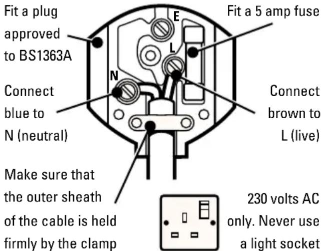
- Before replacing the top cover of the plug ensure that the cable restraint is holding the outer sheath of the cable firmly and that the two leads are correctly fixed at the terminal screws. If the fuse cover is missing or damaged do not use the plug. For replacement or detachable fuse covers, contact a Black & Decker service agent.
Warning! Never connect live or neutral wires to the earth pin marked E or 12
MAINS PLUG REPLACEMENT
(AUSTRALIA AND NEW ZEALAND ONLY)
Should the mains plug or cordset of the product be damaged, it must only be replaced by an authorised
ENGLISH
Black & Decker service agent because special purpose tools are required.
EXTENSION CABLES
Up to 30m (100ft) of 3-core extension cable can be used without undue loss of power. Note: An extension cable should not be used unless absolutely necessary. Use of an improper extension cable could result in a risk of fire and electric shock. If an extension cable must be used, make sure it is properly wired, contains the correct rated fuse as recommended in its literature and is in good electrical condition.
UNWANTED TOOLS AND THE ENVIRONMENT

Should you find one day that the tool needs replacement or is of no further use, think of the protection of the environment. Black & Decker service agents will accept old tools and will dispose of them in an environmentally safe way.
THE BLACK & DECKER GUARANTEE (UK, AUSTRALIA AND NEW ZEALAND ONLY)
If the Black & Decker product becomes defective due to faulty materials and workmanship, within 24 months from the date of purchase, we guarantee to either replace all defective parts or at our discretion, replace the unit free of charge provided that:
• The product is returned to us or our authorised repairers with evidence of date of purchase.
• The product has not been used for trade, professional or hire purposes.
• The product has not been subjected to misuse or neglect.
- The product has not sustained any damage through foreign objects, substances or accidents.
• Repairs have not been attempted by anyone other than our authorised repair agents.
This guarantee is offered as an extra benefit and is additional to the customers statutory rights.
AFTER SALES SERVICE FOR YOUR BLACK & DECKER PRODUCT (UK, AUSTRALIA AND NEW ZEALAND ONLY)
Black & Decker offers a nationwide network of authorised service agents. The use of other than genuine Black & Decker accessories and parts may damage or reduce the performance of your Black & Decker product and may also endanger the user. The terms and conditions of the warranty may also be effected.
OUR AFTER SALES SERVICE POLICY (UK, AUSTRALIA AND NEW ZEALAND ONLY)
It is our aim that all Black & Decker customers should be totally satisfied with their Black & Decker product and after sales service, but if help or advice is needed please contact your local Black & Decker authorised repair agent who will be happy to help. Full details of our after sales service and a list of these agents can be found on the Internet at www.2helpU.com. Alternatively, call our Service and Information Centre whose number you will find towards the back of this manual.
ACCESSORIES
The performance of any power tool is dependant upon the accessory used. Black & Decker accessories are engineered to high quality standards and are designed to enhance the performance of your tool. Buying a Black & Decker accessory will ensure that you get the very best from your Black & Decker tool.
TECHNICAL DATA
The level of sound pressure of the tool is in accordance with EEC legislation. It is recommended that you take appropriate measures for the protection of your hearing if the sound level seems uncomfortable. This normally equates to a sound pressure in excess of 85dB (A).
FEATURES
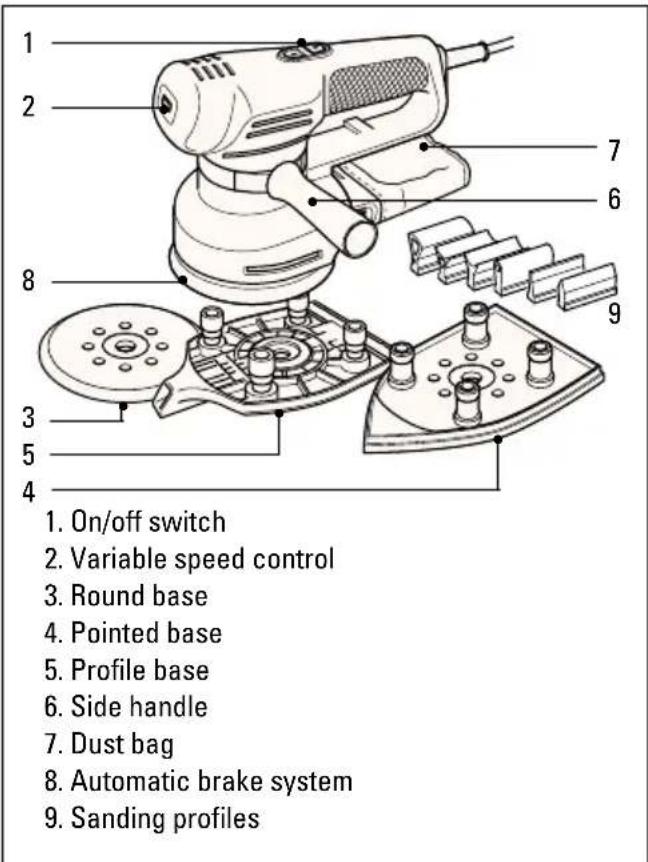
Note: This user manual also covers more than one catalogue number within this product group. Refer to your carton for details of your product.
ENGLISH
OPERATING YOUR MULTI SANDER
natural_image
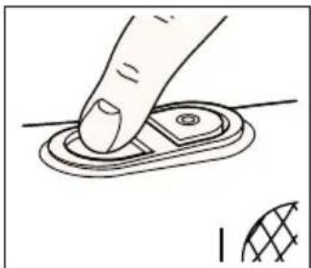
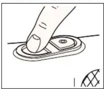
Hand pressing a button on a circular component, with a small inset showing a grid pattern (no text or symbols)To switch your multi sander on, press the on/off switch on the side marked "I". To switch your multi sander off, press the on/off switch on the side marked "O".
Before plugging your multi-sander in, make sure it is switched off.
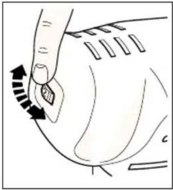
VARIABLE SPEED CONTROL (KA210E/KA220E/KA230E)
natural_image
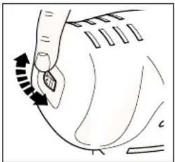
Diagram of a hand pressing down on a curved mechanical component with directional arrows indicating motion (no text or symbols)The variable speed control gives the best operating performance for each material. As a general rule, use low speed for polishing and for sanding acrylic/synthetic materials, and high speed for wood and metal.
Material Variable speed setting
Hardwood (beech) 4-5
Softwood (pine) 4-5
Veneer wood 3-5
Synthetic materials 3-4
Acrylic sheet 1-3
Non-ferrous metals 4-5
Steel 4-5
Lacquer and paint removal 4-5
Polishing 1-3
Rust removal 4-5
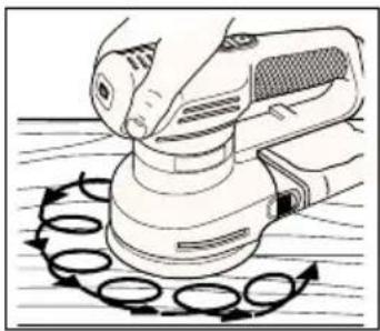
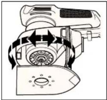
USING YOUR MULTI SANDER AS A RANDOM ORBITAL SANDER (KA200/KA220/KA220E/KA230E)
natural_image
Illustration of a hand using a power tool on a circular base with motion arrows (no text or symbols)With the round base fitted, you can use your multi sander as a random orbital sander. This gives a circular/orbital movement, combined with a rotational movement;
thus giving improved stock removal and reduced risk of swirl marks.
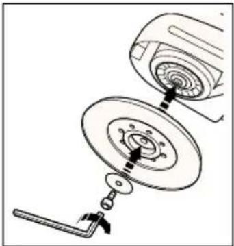
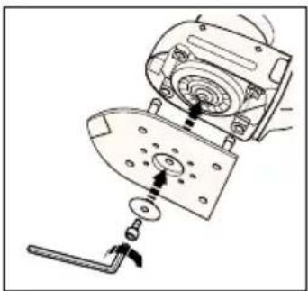
FITTING THE ROUND BASE
Disconnect the plug from the electricity supply.
natural_image
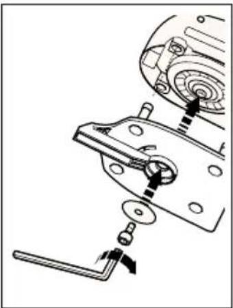
Technical line drawing of a mechanical assembly with no visible text or symbolsPosition the round base on the spindle.
Position the washer on the spindle and fit the screw. Hold the base and tighten the screw with the allen key provided. The base will wear after some time. Replacements are
available as an accessory.
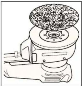
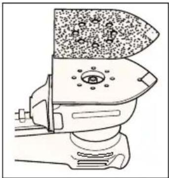
FITTING THE SANDPAPER (ROUND BASE)
Disconnect the plug from the electricity supply.
natural_image
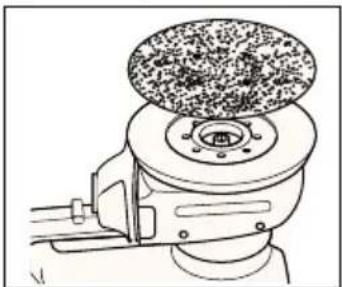
Line drawing of a mechanical grinding machine with a circular component on top (no text or symbols)Hold your multi sander with the base upwards. Press the sandpaper disc onto the base, making sure the base is completely covered. It is not necessary to align the holes in the paper and the base. Never use your multi
sander without a sandpaper disc.
USING YOUR MULTI SANDER IN THE ORBITAL MODE (KA210/KA210E/KA220/KA220E/KA230E)
Detail sanding
Use your multisander with the point of the base pointing forwards. This position permits you to sand into difficult or confined areas.
Orbital sanding
Use your multi-sander with the point of the base to the rear. This permits you to sand large areas with areas and corners that have easy access.
FITTING THE POINTED BASE
Proceed as follows:
Disconnect the plug from the electricity supply.
natural_image
Mechanical assembly diagram showing a disassembly or disassembly process with no visible text or symbolsPosition the pointed base on the spindle, making sure the legs of the base fit into their housings. The base will wear after some time. Replacements are available as an accessory. Place the
washer in position on the base and fit the screw using
ENGLISH
the allen key provided. Press the base on firmly when tightening the screw.
REVERSING THE POINTED BASE (KA210/KA210E/KA220/KA220E/KA230E)
Proceed as follows:
Disconnect the plug from the electricity supply.
natural_image
Diagram of a mechanical device with rotating components and directional arrows indicating motion (no text or symbols)Turn the screw anticlockwise using the allen key provided in the handle. Remove the screw and the washer from the spindle. Hold the base in position with the point facing rearwards. Fit the
washer and the screw. Tighten the screw using the allen key provided. Press the base on firmly when tightening the screw.
FITTING THE SANDPAPER (POINTED BASE)
Proceed as follows:
Disconnect the plug from the electricity supply.
natural_image
Technical line drawing of a mechanical device with granular material and circular components (no text or symbols)Detach the two diamond-shaped tips from the main sheet. Place the sandpaper on the pointed base, making sure the holes of the paper and the base are aligned. Never use your multi sander without sandpaper and always
use a full sheet of sandpaper.
TIP COMPONENTS (POINTED BASE) (KA210/KA210E/KA220 /KA220E/KA230E)
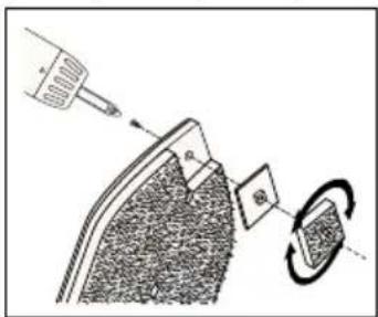
Each sheet of sandpaper has a removable tip, with two spare tips attached. To obtain maximum use from each sheet, detach and turn the tip when the front part is worn.
When the whole tip is worn, replace it with one of the spare tips provided. The tip of the backing pad is removable. When the front part is worn, turn the tip. When the tip is completely worn, replace the tip. Spare tips are available as accessories. When the tip of the
hard plastic tip holder is worn, remove the screw and turn the holder. Spare holders are available as accessories.
FITTING THE PROFILE BASE (KA230E)
Proceed as follows:
Disconnect the plug from the electricity supply.
natural_image
Mechanical assembly diagram showing a clamping mechanism with no visible text or symbolsPosition the profile base on the spindle, with the long section pointing towards the front of your sander. Make sure the legs fit into their housings. Place the washer in position on the base and fit the screw using the allen key provided. Press the base on
firmly when tightening the screw.
FITTING THE SANDING PROFILE (KA230E)
Proceed as follows:
Disconnect the plug from the electricity supply.
natural_image
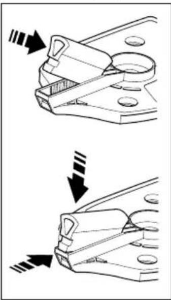
Technical illustration showing two mechanical clamping steps with arrows indicating motion direction (no text or symbols)There are six sanding profiles supplied, each being different in size and shape. Select the sanding profile most suitable for the task and push into the slot in the front of the base. To do this, first locate one end of the sanding profile into the recess at the back of the profile base slot, then push the other end so that it locates in the recess in the front of
the profile base. The sanding profile will now be positively located. The sanding profile can be removed by depressing the small black square section which is visible at the front of the profile base, whilst pulling the profile away from its locating slot.
FITTING THE SANDING PAPER (PROFILE BASE) (KA230E)
Proceed as follows:
Disconnect the plug from the electricity supply.
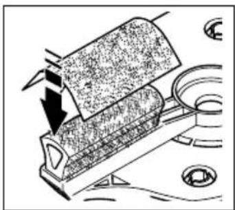
With the profile fitted in the base, fit the paper by
ENGLISH
natural_image
Diagram of a mechanical device with arrows indicating force or movement, no visible text or symbolsapplying light pressure making sure that the paper follows the shape. Never use your sander without sandpaper.
REMOVING THE SIDE HANDLE
Proceed as follows:
natural_image
Technical line drawing of a mechanical device with no visible text or symbolsTurn the handle anti-clockwise and unscrew completely. Remove the connecting shoulder. Unclip the metal clip.
ADJUSTING THE SIDE HANDLE
Proceed as follows:
natural_image
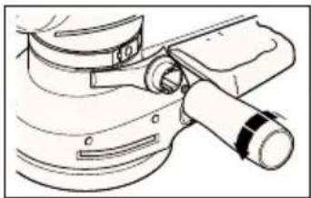
Line drawing of a handheld industrial machine with no visible text or symbolsLoosen the handle slightly. Move the metal clip around the body of the sander until the side handle is in the desired position. Tighten the handle.
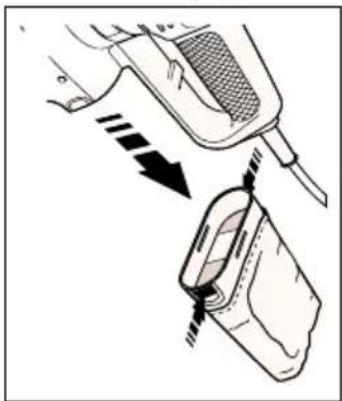
Most of the dust from the work surface is collected in the dustbag. The extraction fan of your multi sander draws the dust from the surface through the holes in the base. The dust then passes through the fan shroud to the dustbag. You can also use your multi sander with a vacuum cleaner. A special adaptor is available from Black & Decker as an accessory.
Disconnect the plug from the electricity supply.
natural_image
Diagram showing a mechanical device with arrows indicating motion or force, no text or symbols presentHold your multi sander vertically with the dustbag facing downwards. Squeeze the sides of the dustbag together, adjacent to the finger grips and pull the bag gently. Empty the dustbag and replace on the sander. A click is
heard when the dustbag is correctly fitted. The plastic baffle is removable. However, it is not necessary to remove the baffle when emptying the dustbag. Do not wash the dustbag. Empty the dustbag every 10 minutes.
AUTOMATIC BRAKE SYSTEM (ABS) (KA200/KA220/KA220E/KA230E)
Your multi sander has an automatic brake system (ABS). This feature gives you optimal control as it keeps the speed of the disc below that of the motor when your sander is not on the work surface. When your sander is switched off, the disc stops very quickly.
HANDY HINTS
natural_image
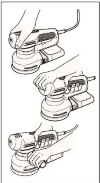
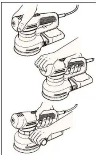
Illustration of three hands using a power tool to adjust a circular component (no text or symbols present)You can hold your multi sander in various positions for maximum comfort but make sure you do not block the air intake slots.
- Do not apply excessive pressure when you use your multi sander, especially in the random orbit mode.
- Replace the sandpaper when it is worn.
- Use high grit sandpaper for a fine finish. As a general rule, start with coarse grits and gradually change to the finer grits for the final finish.
- When using your multi sander to sand profiles be sure to keep the profile square to the workpiece.
- Smaller radii sanding profiles work better with finer grit sandpaper.
- Ensure that the platen is flat on the work surface whilst sanding.
EC DECLARATION OF CONFORMITY
We declare that units:
KA200, KA210, KA210E, KA220, KA220E, KA230E
conform to 89/392/EEC, 89/336/EEC, EN55014,
73/23/EEC, EN55104, EN50144
A weighted sound pressure 77.1dB (A)
ENGLISH
A weighted sound power 90.1dB (A) Hand/arm weighted vibration <2.5m/s²

Brian Cooke - Director of Engineering Black & Decker Ltd, Spennymoor, County Durham DL16 6JG United Kingdom
The Black & Decker policy is one of continuous improvement to our product and as such we reserve the right to change the product specification without prior notice.
Multilijadora - manual de instrucciones
natural_image
Hand pressing a button on a circular component (no text or symbols visible)natural_image
Illustration of a hand pressing a button with a curved arrow indicating motion (no text or symbols)natural_image
Illustration of a hand using a power tool on a circular workpiece (no text or symbols visible)natural_image
Mechanical assembly diagram showing a motor and gear assembly (no text or symbols)natural_image
Line drawing of a mechanical device with a circular component on top (no text or symbols)natural_image
Diagram of a device's internal components and parts, showing a lid, base, and adjustment knobs (no text or labels)natural_image
Technical line drawing of a mechanical device with rotating components and directional arrows (no text or symbols)natural_image
Technical line drawing of a mechanical device with a textured top section and base mount (no text or symbols)natural_image
Mechanical assembly diagram showing a gear and mounting bracket with no visible text or symbolsnatural_image
Technical illustration showing two mechanical clamping steps with arrows indicating motion direction (no text or symbols)natural_image
Diagram of a mechanical device with a rotating component and directional arrows indicating motion (no text or symbols)natural_image
Technical line drawing of a mechanical component with no visible text or symbolsnatural_image
Line drawing of a power tool with meshing and adjustment knob (no text or symbols)natural_image
Diagram showing a device with a meshed top and a close-up of its internal components, no text or symbols present.(KA200/KA220/KA220E/KA230E)
natural_image
Illustration of three hands using a power tool on a sanding machine, showing step-by-step installation (no text or symbols present)natural_image
Hand pressing a button on a circular component, with an arrow symbol indicating rotation (no text or labels)natural_image
Illustration of a finger pressing down on a curved mechanical component with directional arrows indicating motion (no text or symbols)natural_image
Illustration of a hand using a power tool on a circular workpiece (no text or symbols visible)natural_image
Diagram of a mechanical assembly showing a disc with internal components and a tool (no text or symbols)natural_image
Line drawing of a mechanical device with a textured top and central hub (no text or symbols)natural_image
Mechanical assembly diagram showing a device with a handle and internal components (no text or symbols)natural_image
Technical diagram of a mechanical device with rotating components and directional arrows indicating motion (no text or labels)natural_image
Line drawing of a mechanical device with textured surfaces and a central hub (no text or symbols)POINTES (PLATEAU POINTU) (KA210/KA210E/KA220/KA220E/KA230E)
COMMENT PLACER LE PLATEAU POUR PROFILÉS (KA230E)
natural_image
Mechanical assembly diagram showing a clamping mechanism with no visible text or symbolsnatural_image
Technical illustration showing two mechanical clamping steps with arrows indicating motion direction (no text or symbols)natural_image
Diagram of a mechanical device with a rotating component and directional arrows indicating motion (no text or symbols)natural_image
Mechanical assembly diagram showing a lever mechanism with no visible text or symbolsnatural_image
Line drawing of a handheld industrial power tool with no visible text or symbolsnatural_image
Diagram showing a device being inserted into a container with arrows indicating direction (no text or symbols present)(KA200/KA220/KA220E/KA230E)
natural_image
Illustration of three hands using a power tool on a sanding machine (no text or symbols visible)KA200, KA210, KA210E, KA220, KS220E, KA230E
Black & Decker Ltd, Spennymoor, County Durham
DL16 6JG United Kingdom
natural_image
Hand pressing a button on a circular component (no text or symbols visible)natural_image
Diagram showing a hand pressing down on a curved object with directional arrows indicating motion (no text or symbols)natural_image
Illustration of a hand using a power tool on a circular base with circular arrows indicating rotation (no text or symbols)natural_image
Diagram of a mechanical device with a rotating component and a spring-loaded mechanism (no text or symbols)natural_image
Line drawing of a manual milling machine with a textured top (no text or symbols)natural_image
Mechanical assembly diagram showing a device with rotating components and a base component (no text or symbols)natural_image
Technical diagram of a mechanical device with rotating components and directional arrows (no text or labels)natural_image
Line drawing of a mechanical device with granular material and mounting base (no text or symbols)natural_image
Mechanical assembly diagram showing a disassembly of a mechanical component with gears and levers (no text or labels)natural_image
Technical illustration showing two mechanical clamping steps with arrows indicating motion direction (no text or symbols)natural_image
Diagram of a mechanical device with arrows indicating motion or force direction (no text or symbols)natural_image
Technical line drawing of a mechanical assembly with no visible text or symbolsnatural_image
Line drawing of a handheld electric shaver with mesh and lever mechanism (no text or symbols)natural_image
Diagram showing a device being inserted into a container with arrows indicating direction (no text or symbols present)natural_image
Illustration of three different hand-painted views of a power tool, showing step-by-step installation (no text or symbols present)Brian Cooke - Director of Engineering Black & Decker, Spennymoor, Co Durham DL16 6JG, UK
natural_image
Hand pressing a circular component on a surface, with a small cross symbol nearby (no text or symbols present)natural_image
Illustration of a hand pressing down on a curved object with an arrow indicating rotation (no text or symbols)natural_image
Illustration of a hand using a power tool on a circular base with directional arrows indicating rotation (no text or symbols)natural_image
Mechanical assembly diagram showing a motor with rotating components and a lever mechanism (no text or symbols)natural_image
Technical line drawing of a mechanical device with a circular component on top (no text or symbols)natural_image
Mechanical assembly diagram showing a device with internal components and a tool (no text or symbols)natural_image
Technical diagram of a mechanical device with directional arrows indicating motion or flow (no text or symbols)natural_image
Line drawing of a mechanical device with granular material and a central hub (no text or symbols)natural_image
Mechanical assembly diagram showing a gear and adjustment mechanism (no text or labels)natural_image
Technical illustration showing two mechanical clamping steps with arrows indicating motion direction (no text or symbols)natural_image
Diagram of a mechanical device with arrows indicating motion or force direction (no text or symbols)natural_image
Line drawing of a mechanical component with a handle and lever (no text or symbols)De metalen klem losmaken.
DE ZIJHANDGREEP BIJSTELLEN
natural_image
Line drawing of a mechanical power tool with no visible text or symbolsnatural_image
Diagram showing a hand holding a device with arrows indicating motion or force (no text or symbols present)AUTOMATISCH REMSYSTEEM (ABS) (KA200/KA220/KA220E/KA230E)
natural_image
Three-step line drawing showing hands using a power tool to adjust a motor (no text or symbols present)KA200, KA210, KA210E, KA220, KA220E, KA230E
in overeenstemming is met 89/392/EEC, 89/336/EEC,
NEDERLANDS
EN55014, 73/23/EEC, EN55104, EN50144
Black & Decker Ltd, Spennymoor, County Durham
DL16 6JG, United Kingdom
Merk: Denne brukerhåndboken dekker mer enn ett katalognummer innen denne produktgruppen. For nærmere detaljer se produktets eske.
BRUKE SLIPEMASKINEN
natural_image
Hand pressing a circular component on a surface, with no visible text or symbolsnatural_image
Illustration of a hand pressing down on a curved mechanical component with directional arrows (no text or symbols)natural_image
Illustration of a hand using a power tool on a circular workpiece with directional arrows (no text or symbols)natural_image
Mechanical assembly diagram showing a motor and gear assembly with no visible text or symbolsSett den runde støtteskiven på spindelen. Sett tetningsskiven på spindelen og fest skruen. Hold skiven og stram skruen med medfølgende sekskantnøkkel. Skiven blir slitt etter en stund.
SETTE PÅ SLIPEPAPIR (RUND SLIPEPLATE)
Gjør slik:
Trekk ut støpselet.
natural_image
Technical line drawing of a mechanical device with a textured top and central hub (no text or symbols)Hold slipemaskinen med støtteskiven opp. Trykk sandpapiret på skiven. Pass på at skiven blir dekket helt. Du trenger ikke justere hullene i papiret i forhold til skiven. Du må aldri
bruke slipemaskinen uten sandpapir.
BRUKE SLIPEMASKINEN SOM DE TALJSLIPER (KA210/KA210E/KA220/KA220E/KA230E)
Detaljsliping
natural_image
Diagram of a device with a mechanical component and a tool, showing internal components and motion indicators (no text or symbols)natural_image
Technical line drawing of a mechanical device with directional arrows indicating motion or flow (no text or symbols)natural_image
Line drawing of a toilet with granular material inside (no text or symbols)(KA210/KA210E/KA220/KA220E/KA230E)
natural_image
Diagram showing a tool interacting with a device, possibly a camera or display unit (no text or symbols present)MONTERE PROFILBASEN (KA230E)
Gjør slik:
natural_image
Mechanical assembly diagram showing a clamping mechanism with no visible text or symbolsnatural_image
Technical illustration showing two mechanical clamping steps with arrows indicating motion direction (no text or symbols)natural_image
Diagram of a mechanical device with directional arrows indicating motion or force (no text or symbols)natural_image
Technical line drawing of a mechanical assembly with no visible text or symbolsnatural_image
Line drawing of a power tool with meshing and adjustment knob (no text or symbols)natural_image
Diagram showing a device being inserted into a container with arrows indicating motion (no text or symbols present)händtakene, og trekk forsiktig i posen. Tøm posen og sett den tilbake på maskinen. Du hører et klikk når den sitter som den skal. Det harde plastskallet er avtakbart. Det er ikke nødvendig å fjerne plastskallet når du tømmer sponposen. Vask ikke sponposen.
Tøm sponposen hvert 10. minutt.
AUTOMATISK BREMSESYSTEM (ABS)
(KA200/KA220/KA220E/KA230E)
Slipemaskinen har et automatisk bremsesystem (ABS). Dette gir deg optimal kontroll, fordi det holder skivehastigheten lavere enn motorhastigheten när slipemaskinen ikke er på arbeidsflaten. Når du plasserer maskinen på arbeidsflaten, øker skivehastigheten, fordi ABS-kontrollen koples ut. Når slipemaskinen slås av, stanser skiven raskt.
TIPS
natural_image
Illustration of three hands using a power tool on a base, showing different angles and components (no text or symbols present)Du kan holde slipemaskinen i forskjellige stillinger for maksimal komfort. Pass på at du ikke blokkerer luftinntaket.
89/336/EEC, EN55014, 73/23/EEC, EN55104, EN50144
Brian Cooke - Director of Engineering
Black & Decker Ltd, Spennymoor, County Durham
DL16 6JG, United Kingdom
Manual do utilizador para a multi-lixadora
INSTRUÇÕES DE SEGURANÇA
natural_image
Hand pressing a button on a circular component (no text or symbols visible)natural_image
Illustration of a hand pressing down on a curved mechanical component (no text or symbols)natural_image
Illustration of a hand using a power tool to press or move a circular component, with no visible text or symbols.natural_image
Mechanical assembly diagram showing a gear and wheel assembly with no visible text or symbolsnatural_image
Line drawing of a mechanical device with a textured top and central hub (no text or symbols)natural_image
Mechanical assembly diagram showing a device with internal components and a handle (no text or symbols)natural_image
Diagram of a mechanical device with directional arrows indicating motion or flow, no readable text or symbols present.natural_image
Line drawing of a mechanical device with textured surfaces and a central component (no text or symbols)natural_image
Mechanical assembly diagram showing a motor and clamping mechanism (no text or labels)natural_image
Technical illustration of a mechanical clamp or bracket assembly (no text or symbols)natural_image
Diagram of a mechanical device with a rotating component and a downward arrow indicating motion (no text or symbols)natural_image
Line drawing of a mechanical component with a lever and handle (no text or symbols)natural_image
Line drawing of a handheld electric shaver with mesh control (no text or symbols)natural_image
Diagram showing a device being inserted into a container with arrows indicating motion (no text or symbols present)natural_image
Illustration of three different hand-painted views of a power tool, showing step-by-step application (no text or symbols present)KA200, KA210, KA210E, KA220, KS220E, KA230E
estão de acordo com 89/392/EEC, 89/336/EEC, EN55014, 73/23/EEC, EN55104, EN50144
Black & Decker Ltd, Spennymoor, County Durham DL16 6JG, United Kingdom
natural_image
Hand pressing a button on a circular component (no text or symbols visible)natural_image
Illustration of a hand pressing down on a curved surface with directional arrows (no text or symbols)natural_image
Illustration of a hand using a power tool on a circular workpiece (no text or symbols visible)natural_image
Mechanical assembly diagram showing a device with rotating components and a lever (no text or symbols)natural_image
Line drawing of a mechanical device with a circular top component (no text or symbols)natural_image
Mechanical assembly diagram showing a device with internal components and directional arrows (no text or symbols)natural_image
Technical line drawing of a mechanical device with directional arrows indicating motion or flow (no text or symbols)natural_image
Diagram of a mechanical component with granular top and circular feature, no text or symbols presentMUOTOILUALUSTAN KIINNITYS (KA230E)
natural_image
Mechanical assembly diagram showing a clamping mechanism with no visible text or symbolsnatural_image
Technical line drawing of a mechanical clamp or bracket assembly (no text or symbols)natural_image
Diagram of a mechanical component with arrows indicating force or movement (no text or symbols)HIOMAPAPERIN KIINNITYS (MUOTOILUALUSTA) (KA230E)
natural_image
Diagram of a mechanical device with arrows indicating motion or force direction (no text or symbols)natural_image
Technical line drawing of a mechanical assembly with no visible text or symbolsnatural_image
Line drawing of a mechanical power tool with no visible text or symbolsnatural_image
Diagram showing a device being inserted into a plastic container with arrows indicating direction (no text or symbols present)natural_image
Three-step illustration of hands using a power tool to clean a circular component (no text or symbols present)Brian Cooke - Director of Engineering Black & Decker Ltd, Spennymoor, County Durham DL16 6JG, United Kingdom
natural_image
Hand pressing a button on a circular component (no text or symbols visible)natural_image
Illustration of a hand pressing down on a curved surface with directional arrows indicating motion (no text or symbols)natural_image
Illustration of a hand using a power tool on a wooden surface with circular motion arrows (no text or symbols)natural_image
Diagram of a mechanical assembly with a gear and housing component (no text or symbols)natural_image
Line drawing of a manual grinding machine with a circular top component (no text or symbols)natural_image
Diagram of a robotic vacuum cleaner with mechanical components and motion arrows (no text or symbols)natural_image
Technical diagram of a mechanical device with rotating components and directional arrows (no text or symbols)natural_image
Technical line drawing of a mechanical device with granular material and circular components (no text or symbols)natural_image
Mechanical assembly diagram showing a clamping mechanism with no visible text or symbolsnatural_image
Technical illustration showing two mechanical clamping steps with arrows indicating motion direction (no text or symbols)natural_image
Diagram of a mechanical device with a rotating roller and directional arrow, no visible text or symbolsnatural_image
Technical line drawing of a mechanical device with a lever and base (no text or symbols)natural_image
Line drawing of a power tool with meshing and adjustment knobs (no text or symbols)natural_image
Diagram showing a device being inserted into a container with arrows indicating motion (no text or symbols present)natural_image
Three-step line drawing of a hand using a power tool, showing step-by-step application (no text or symbols)Brian Cooke - Director of Engineering Black & Decker Ltd, Spennymoor, County Durham DL16 6JG, United Kingdom
| Indkøbsdato |
| Kaufdatum |
| Ημερομηνία αγοράσ |
| Date of purchase |
| Fecha de compra |
| Date d'achat |
| Data d'acquisto |
| Aankoopdatum |
| Innkjøpsdato |
| Data de compra |
| Ostopäivä |
| Inköpsdatum |
| Forhandler adresse |
| Händleradresse |
| Διεύθυνση αντιπροσώπου |
| Address of dealer |
| Dirección del detallista |
| Cachet du revendeur |
| Indirizzo del rivenditore |
| Adres van de dealer |
| Forhandlerens adresse |
| Morada do revendedor |
| Jälleenmyyjän osoite |
| Återförsäljarens adress |
| Navn/Name/Ovoμα/Name/Nombre/Nom/Nome/Naam/Navn/Nome/Nimi/Namn:____Adresse/Adresse/ΔιεύθυνσηAddress/Dirección/Adresse/Indirizzo/Adres/Adresse/Morada/Osoite/Adress:____By/Wohnort/Πόλη/Town/Ciudad/Ville/Cittá/Plaats/By/Localidade/Paikkakunta/By:____Postnr./Postleitzahl/Kωδικόσ/Postcode/Code postal/Código/Codice postale/Postcode/Postnr./Código postal/Postinumero/Postnr.:____Er maskinen en gave?/Ist diese Maschine ein Geschenk?/H μηχανή είναι δώρο?/Is this product a gift?/¿Ha recibido usted esta herramienta como regalo?/S’agit-il d’un cadeau?/Si tratta di un regalo?/Kreeg u deze | machine cadeau?/Er maskinen en gave?/Recebeu esta ferramenta como presente?/Onko kone lahja?/Är maskinen en gåva?Ja/Ja/Nai/Yes/Sí/Oui/Si/Ja/Ja/Sim/Kyllä/JaNej/Nein/Oχv/No/No/Non/No/Nee/Nei/Não/Ei/NejHvor meget kostede maskinen?/Was war der Preis dieses Werkzeuges?/Ποιά είναι η τιμή του εργαλείου αυτού?/What was the price of this tool?/?Cual fue el precio de esta herramienta?/Prix payé?/Quanto ha pagato questo prodotto?/Wat was de prijs van dit produkt?/Hvor meget kostet maskinen?/Que preço pagou por esta ferramenta?/Paljonko kone maksoi?/Hur myket kostade maskinen?____Er dette din første B&D maskine?/Ist dieses Werkzeug-/Eïvaı to εργαλείο αυτό-/Is this tool-/?Es esta herramienta que comprado-/Est-ce-/Questo prodotto è-/Is deze machine-/Er dette din første B&D maskin?/Esta ferramenta é-/Onko tämä ensimmäinen B&D-koneesi?/Är detta Din första B&D-velu?↑ | Ja/ein Erstkauf?/?η πρώτη σασ αγορά?/your first purchase?/?la primera de este tipo?/?un ler achat?/?il suo primo acquisto?/?uw eerste aankoop?/?Ja/a sua primeira compra?/?Kyllä/JaNej/Ersatzkauf?/?για αντικατάσταση?/?a replacement?/?un reempalzo?/?un achat de remplacement?/?una sostituzione?/?een vervanging?/?Nei/uma substitução?/?Ei/NejForhandler adresse/Händleradresse/Διεύθυνση αντιπροσώπου/Address of dealer/Dirección del detallista/Cachet du revendeur/Indirizzo del rivenditore/Dealeradres/Forhandlerens adresse/Morada do revendedor/Jälleenmyyjän osoite/Äterförsäljarens adress:Cat. no. KA2__/_ __ __ | Venligst sæt kryds i ruden såfremt De ikke måtte ønske at modtage information fra anden virksomhed end Black & Decker.Bitte ankreuzen, falls Sie weiteres Informationsmaterial von Black & Decker erhalten möchten.Паракалείσθε να σημειώσετε εάν δέν θέλετε να πάρετε πληροφορίεσ άλλησ εταιρείασ εκτόσ τησ Black & Decker.Data protection act: Tick the box if you prefer not to receive information from us or others.Señale en la casilla sino quiere recibir información de otras empresas.Si vous ne souhaitez pas recevoir d’informations de la part d’autres sociétés que Black & Decker, cochez cette case.Barrate la casella se non desiderate ricevere informazioni da altre aziende.A.u.b.dit vakje aankruisen indien u geen informatie wenst te ontvangen van andere bedrijven dan Black & Decker.Vennligst kryss av dersom De ikke ønsker informasjon fra andre bedrifter enn Black & Decker.Por favor, assinale com uma cruz se desejar receber informação de outras empresas, além da Black & Decker.Merkitkää rasti ruutuun, mikäli ette halua vastaanottaa informaatiota muulta taholta kuin Black & Deckeriltä.Vänligen kryssa för i rutan om Ni inte vill ha information från andra företag än Black & Decker. |
| • GARANTI KORT • GARANTIEKARTE • KAPTA EFFYHZH • GUARANTEE CARD • TARGETA DE GARAINTIA • CARTE DE GARANTIE | ||||||||||||||
| • TAGUANDO DI GARANIZIA • GARANTIE-KART • GARANTI KORT • CARTAO DE GARAINTIA • TAKUKORITI • GARANTIBEVS | ||||||||||||||
| Belgique/Belgie | Wethoek 1, 1930 Zaventem | Nederland | Florintrastat 10, 4879 AH Eten-Leur | Norge | Österreich | Portugal Rua Egas, Moniz 173, S. João do Estrol, 2768 Estrol Codex | South Africa Black & Decker, Suite 107, PN X65, Hafway Hse, 1685 | |||||||
| Deutschland | Black & Decker Star. 40, D-65510 Idstein | Stromsveien 344, 1081 Osló | Österreich | Egrader Straise 165, 1231 Wien | Erlaer Straise 165, 1231 Wien | Portugal Rua Egas, Moniz 173, S. João do Estrol, 2768 Estrol Codex | Portugal Rua Egas, Moniz 173, S. João do Estrol, 2768 Estrol Codex | |||||||
| Espagne | 43883 Roda de Bara (Tarragona) | Büttstärke 14, 8952 Schiieren, Schwierz/Suisse | Sơni | Swinge | Black & Decker OY, Raissite 7C, 01510 Vantaa | Box 603, 421 26 Vastra Froulunda | South Africa Black & Decker, Suite 107, PN X65, Hafway Hse, 1685 | |||||||
| France | BP21, 69571 Dardilly Cedex | Ruitstrasse 14, 8952 Schiieren, Schwierz/Suisse | Sơni | Swinge | Black & Decker OY, Raissite 7C, 01510 Vantaa | Box 603, 421 26 Vastra Froulunda | South Africa Black & Decker, Suite 107, PN X65, Hafway Hse, 1685, | |||||||
| Italia | Viale Eviezia 2, 20052 Monza (Mll) | Viale Eviezia 2, 20052 Monza (Mll) | UK & Ireland | PO Box 821, Slough, Berkshire, SL1 348 | Allindirizzo della Black & Decker nella vostra nazione (vedi sopra). | Knip dit gadelete uit, zend het in een gerankeerde, geardresseerde envelop direct na uw aankoor naar het Black & Decker-adres in uw land (zie boven). Venintigst kliput denne delen unmiddeibart efter du har pakket uit dit product og legg det! en adressert konvolut til Black & Decker (Norge) A/S (se adresse over). Black & Decker (Norge) | Norge | Nordans | Martechen | Bitte schneiden Sie diesen Abschmitt ab, stateken ihn in einen Black & Decker Adresse Ihres Landes. | Tangopecakly kofyte aucto to koulakt kal toxupolohre to alectowo luedta tiny avogda tou przovoto qao otmy Azuleuvon tro Black & Decker ortny ezaldoa (Pazine rauw). Please complete this section immediately after the purchase of your product and post it to the Black & Decker adresses in your country (above). If you live in Australia or New Zealand, please register by using the alternative guarantee card supplied. Suomi Leikkawa ini tamba osa, laita se oheseen kuoren ja postata kuroi yllia olevan parkalliseen Black & Decker osotteesen. Var vanilig klipp ur denna del. Skiry Dirt namn och adress pa ett frankerat kuvert, och sand det genast till Black & Deckers adress ! Ditt land (se ovan). | Sverige | Favor, recorte esta parte, colouge-a num envelope selado e onderego da Black & Decker do seu pays. | Frenchais Despues de haber comprado su herarmienta envie usted, por flavor, esta tarjeta a la central de Black & Decker en su pays. I'adresse de Black & Decker dans votre pays (voir ci-dessus), ceci immediatement apres votre achat. |
| English | Venintigst klip denne del ud oz send frankeret il Black & Decker i dit land. | Per favore triangilate questa parte, insertela in una busta con francobollo e speditela subito dopro 'acquistio del prodotto allindirizzo della Black & Decker nella vostra nazione (vedi sopra). | Nordans | Montan | Black & Decker adres in uw land (zie boven). Venintigst kliput denne delen unmiddeibart efter du har pakket uit dit product og legg det! en adressert konvolut til Black & Decker (Norge) A/S (se adresse over). Black & Decker (Norge) | Norge | Portugues Por favor, recorte esta parte, colouge-a num envelope selado e onderegado e envie-o logo apos a compra do seu produto para o anderego da Black & Decker do seu pays. | |||||||
| Elkhviking | Black & Decker Adresse Ihres Landes. | |||||||||||||
| Deutsch | Tangopecakly kofyte aucto to koulakt kal toxupolohre to alectowo luedta tiny avogda tou przovoto qao otmy Azuleuvon tro Black & Decker ortny ezaldoa (Pazine rauw). | |||||||||||||
| English | Please complete this section immediately after the purchase of your product and post it to the Black & Decker adresses in your country (above). If you live in Australia or New Zealand, please register by using the alternative guarantee card supplied. | |||||||||||||
| Français | Descoupe cette parte et envoyez-la sous enveloppe timbrege a l'adresse de Black & Decker dans votre pays (voir ci-dessus), ceci immediatement apres votre achat. | |||||||||||||

- KÆRE KUNDE,
- On the purchase of your Black & Decker product.
- ¡ENHORABUENA!
- HASTIGHEDSREGULATOR (KA210E/KA220E/KA230E)
- T∅MNING AF ST∅VPOSEN
- (KA200/KA220/KA220E/KA230E)
- AUTOMATISCHES BREMSSYSTEM (ABS) (KA200/KA220/KA220E/KA230E)
- KA200, KA210, KA210E, KA220, KS220E, KA230E
- ΕΛΛΗΝΙΚΑ
- Multi sander user manual
- SAFETY INSTRUCTIONS
- FOR SAFE OPERATION:
- ADDITIONAL PRECAUTIONS TO TAKE WHEN SANDING PAINT AND MEDIUM DENSITY FIBREBOARD (MDF)
- PERSONAL SAFETY
- ENVIRONMENTAL SAFETY
- CLEANING AND DISPOSAL
- SAVE THESE INSTRUCTIONS!
- DOUBLE INSULATION
- ELECTRICAL SAFETY
- MAINS PLUG REPLACEMENT (UK ONLY)
- MAINS PLUG REPLACEMENT
- (AUSTRALIA AND NEW ZEALAND ONLY)
- ENGLISH
- EXTENSION CABLES
- UNWANTED TOOLS AND THE ENVIRONMENT
- THE BLACK & DECKER GUARANTEE (UK, AUSTRALIA AND NEW ZEALAND ONLY)
- AFTER SALES SERVICE FOR YOUR BLACK & DECKER PRODUCT (UK, AUSTRALIA AND NEW ZEALAND ONLY)
- OUR AFTER SALES SERVICE POLICY (UK, AUSTRALIA AND NEW ZEALAND ONLY)
- ACCESSORIES
- TECHNICAL DATA
- OPERATING YOUR MULTI SANDER
- VARIABLE SPEED CONTROL (KA210E/KA220E/KA230E)
- Material Variable speed setting
- USING YOUR MULTI SANDER AS A RANDOM ORBITAL SANDER (KA200/KA220/KA220E/KA230E)
- FITTING THE ROUND BASE
- FITTING THE SANDPAPER (ROUND BASE)
- USING YOUR MULTI SANDER IN THE ORBITAL MODE (KA210/KA210E/KA220/KA220E/KA230E)
- Detail sanding
- Orbital sanding
- FITTING THE POINTED BASE
- REVERSING THE POINTED BASE (KA210/KA210E/KA220/KA220E/KA230E)
- FITTING THE SANDPAPER (POINTED BASE)
- TIP COMPONENTS (POINTED BASE) (KA210/KA210E/KA220 /KA220E/KA230E)
- FITTING THE PROFILE BASE (KA230E)
- FITTING THE SANDING PROFILE (KA230E)
- FITTING THE SANDING PAPER (PROFILE BASE) (KA230E)
- REMOVING THE SIDE HANDLE
- ADJUSTING THE SIDE HANDLE
- AUTOMATIC BRAKE SYSTEM (ABS) (KA200/KA220/KA220E/KA230E)
- EC DECLARATION OF CONFORMITY
- KA200, KA210, KA210E, KA220, KA220E, KA230E
- Multilijadora - manual de instrucciones
- POINTES (PLATEAU POINTU) (KA210/KA210E/KA220/KA220E/KA230E)
- COMMENT PLACER LE PLATEAU POUR PROFILÉS (KA230E)
- DE ZIJHANDGREEP BIJSTELLEN
- AUTOMATISCH REMSYSTEEM (ABS) (KA200/KA220/KA220E/KA230E)
- NEDERLANDS
- SETTE PÅ SLIPEPAPIR (RUND SLIPEPLATE)
- BRUKE SLIPEMASKINEN SOM DE TALJSLIPER (KA210/KA210E/KA220/KA220E/KA230E)
- Detaljsliping
- (KA210/KA210E/KA220/KA220E/KA230E)
- MONTERE PROFILBASEN (KA230E)
- AUTOMATISK BREMSESYSTEM (ABS)
- Manual do utilizador para a multi-lixadora
- INSTRUÇÕES DE SEGURANÇA
- MUOTOILUALUSTAN KIINNITYS (KA230E)
- HIOMAPAPERIN KIINNITYS (MUOTOILUALUSTA) (KA230E)
Brand : BLACK & DECKER
Model : KA220E
Category : Sander