
XC50230mmF4.56.7 OIS - Lens FUJIFILM - Free user manual and instructions
Find the device manual for free XC50230mmF4.56.7 OIS FUJIFILM in PDF.
| Product type | Telephoto zoom lens for mirrorless camera with X mount |
| Focal length | 50–230 mm (35mm equivalent: 76–350 mm) |
| Maximum aperture | f/4.5–6.7 |
| Minimum aperture | f/22 |
| Optical construction | 13 elements in 10 groups (including 1 aspherical and 1 extra-low dispersion) |
| Angle of view | 31.7° – 7.1° |
| Image stabilization | OIS (Optical Image Stabilization), can be enabled via camera menu |
| Minimum focus (normal) | 1.1 m (throughout the zoom range) |
| Minimum focus (macro) | 1.1 m – 3 m |
| Maximum magnification | 0.2× (at 230 mm) |
| Number of diaphragm blades | 7 (circular aperture) |
| Aperture control | 1/3 EV increments, 13 EV (15 stops) |
| Filter diameter | 58 mm |
| Dimensions (diameter × length) | 69.5 × 111 mm (wide-angle); 69.5 × 177 mm (telephoto) |
| Weight | 375 g (without caps or hood) |
| Supplied accessories | Front lens cap, rear lens cap, lens hood |
| Mount | Fujifilm X mount (compatible with X-Pro1, X-E1, X-T, X-A, etc.) |
| Focus | Manual (focus ring) and automatic via the camera |
| Zoom | Rotary (zoom ring): turn left for wide-angle, right for telephoto |
| Maintenance and cleaning | Clean optical surfaces with a blower and a soft cloth slightly moistened with ethanol; store in a cool, dry place |
| Safety | Do not disassemble, do not immerse, avoid shocks, do not look at the sun through the lens |
| Repairability | Entrust any repair to an authorized FUJIFILM representative |
Frequently Asked Questions - XC50230mmF4.56.7 OIS FUJIFILM
User questions about XC50230mmF4.56.7 OIS FUJIFILM
0 question about this device. Answer the ones you know or ask your own.
Ask a new question about this device
Download the instructions for your Lens in PDF format for free! Find your manual XC50230mmF4.56.7 OIS - FUJIFILM and take your electronic device back in hand. On this page are published all the documents necessary for the use of your device. XC50230mmF4.56.7 OIS by FUJIFILM.
USER MANUAL XC50230mmF4.56.7 OIS FUJIFILM
XC50-230mmF4.5-6.7 OIS

natural_image
Cross-sectional diagram of a mechanical component with a circular shaft and arrow indicating direction (no text or symbols)レンズフードの取り付け方
ズーム操作
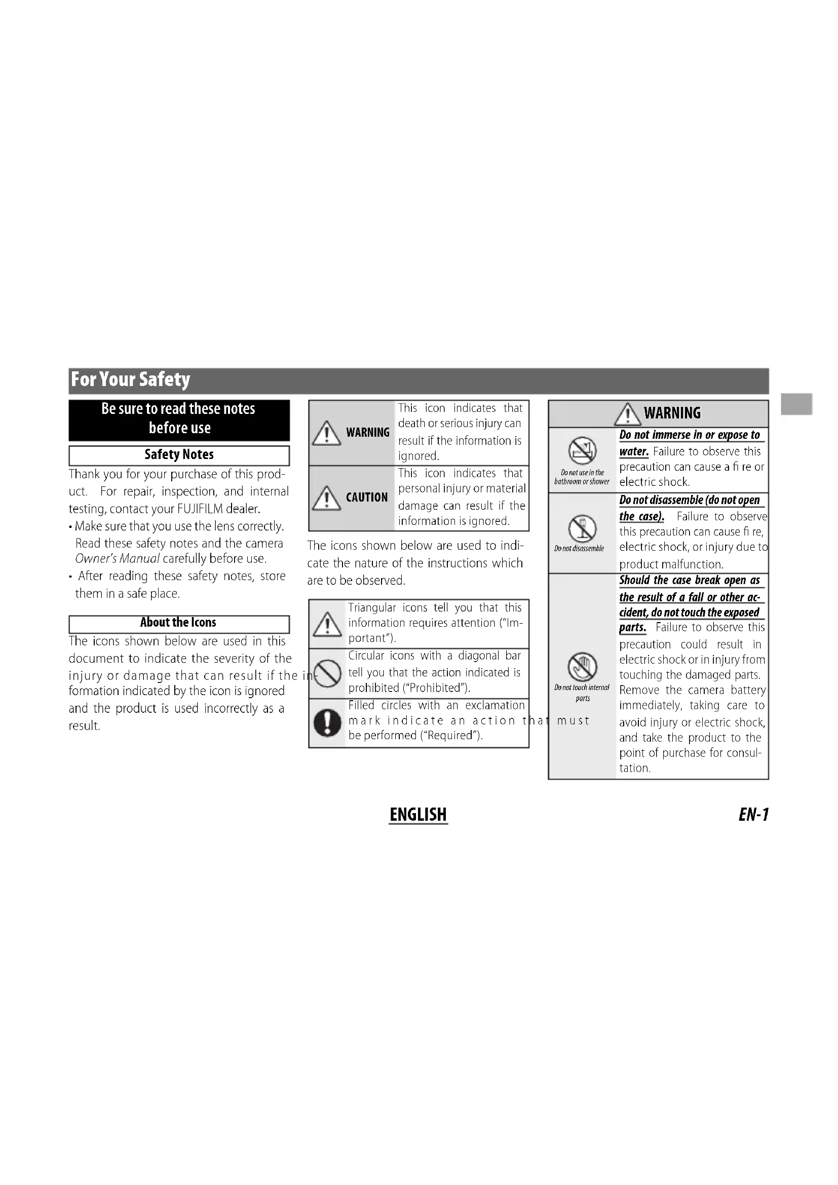
Be sure to read these notes before use
Safety Notes
Thank you for your purchase of this product. For repair, inspection, and internal testing, contact your FUJIFILM dealer.
• Make sure that you use the lens correctly. Read these safety notes and the camera Owner's Manual carefully before use.
• After reading these safety notes, store them in a safe place.
About the Icons
The icons shown below are used in this document to indicate the severity of the injury or damage that can result if the formation indicated by the icon is ignored and the product is used incorrectly as a result.
| This icon indicates that death or serious injury can result if the information is ignored. | |
| This icon indicates that personal injury or material damage can result if the information is ignored. |
The icons shown below are used to indicate the nature of the instructions which are to be observed.
| Triangular icons tell you that this information requires attention ("Important"). | |
| Circular icons with a diagonal bar tell you that the action indicated is prohibited ("Prohibited"). | |
| Filled circles with an exclamation mark indicate an action t be performed ("Required"). |
| WARNING | |
| Do not use in the bathroom or shower | Do not immerse in or expose to water.Failure to observe this precaution can cause a fi re or electric shock. |
| Do not disassemble | Do not disassemble (do not open the case).Failure to observe this precaution can cause fi re, electric shock, or injury due to product malfunction. |
| Do not touch internal parts must | Should the case break open as the result of a fall or other accident, do not touch the exposed parts.Failure to observe this precaution could result in electric shock or in injury from touching the damaged parts.Remove the camera battery immediately, taking care to avoid injury or electric shock, and take the product to the point of purchase for consultation.Do not place on unstable surfaces. The product may fall, causing injury. |
| Do not view the sun through the lens or camera view fi ndFailure to observe this precaution can cause permanent visual impairment. | |
| CAUTION | |
| Do not use or store in locations that are exposed to steam, or smoke or are very humid or extremely dusty. Failure to observe this precaution can cause fi re or electric shock. | |
| Do not leave in direct sunlight or in locations subject to very high temperatures, such as in a closed vehicle on a sunny day.Failure to observe this precaution can cause fi re. | |
WARNING

CAUTION

Do not handle with wet hands. Failure to observe this precaution can cause electric shock.

Keep the sun out of the frame when shooting backlit subjects. Sunlight focused into the camera when the sun is in or close to the frame can cause fire or burns.

When the product is not in use, replace the lens caps and store out of direct sunlight. Sunlight focused by the lens can cause fire or burns.

Do not carry the camera or lens while they are attached to a tripod. The product can fall or strike other objects, causing injury.
For Customers in the U.S.A.
Tested To Comply With FCC Standards FOR HOME OR OFFICE USE
FCC Statement: This device complies with Part 15 of the FCC Rules. Operation is subject to the following two conditions: (1) This device may not cause harmful interference, and (2) this device must accept any interference received, including interference that may cause undesired operation.
CAUTION: This equipment has been tested and found to comply with the limits for a Class B digital device, pursuant to Part 15 of the FCC Rules. These limits are designed to provide reasonable protection against harmful interference in a residential installation. This equipment generates, uses, and can radiate radio frequency energy and, if not installed and used in accordance with the instructions, may cause harmful interference to radio communications. However, there is no guarantee that interference will not occur in a particular installation. If this equipment does cause harmful interference to radio or television reception, which can be determined by turning the equipment off and on, the user is encouraged to try to correct the interference by one or more of the following measures:
- Reorient or relocate the receiving antenna.
- Increase the separation between the equipment and receiver.

- Connect the equipment into an outlet on a circuit different from that to which the receiver is connected.
- Consult the dealer or an experienced radio/TV technician for help.
- You are cautioned that any changes or modifications not expressly approved in this manual could void the user's authority to operate the equipment.
Notes on the Grant: To comply with Part 15 of the FCC Rules, this product must be used with a Fujifi Im-specific ed ferrite-core A/V cable, USB cable, and DC supply cord.
For Customers in Canada
CAUTION: This Class B digital apparatus complies with Canadian ICES-003.
IMPORTANT SAFETY INSTRUCTIONS
- Read these instructions.
- Keep these instructions.
- Heed all warnings.
- Follow all instructions.
- Do not use this apparatus near water (excluding waterproof products).
- Clean only with a dry cloth.
- Do not block any ventilation openings. Install in accordance with the manufacturer's instructions.
- Do not install near any heat sources such as radiators, heat registers, stoves, or other apparatus
(including amplifiers) that produce heat.
- Protect the power cord from being walked on or pinched particularly at plugs, convenience receptacles, and the point where they exit from the apparatus.
- Only use attachments/accessories specified by the manufacturer.
- Unplug this apparatus during lightning storms or when unused for long periods of time.
• Refer all servicing to qualified service personal. Servicing is required when the apparatus has been damaged in any way, such as power supply cord or plug is damaged, liquid has been spilled or objects have fallen into the apparatus, the apparatus has been exposed to rain or moisture, does not operate normally, or has been dropped.
Disposal of Electrical and Electronic Equipment in Private Households
In the European Union, Norway, Iceland and Liechtenstein: This symbol on the product, or in the manual and in the warranty, and/or on its packaging indicates that this product shall not be treated as household waste. Instead it should be taken to an applicable collection point for the recycling of electrical and electronic equipment.

By ensuring this product is disposed of correctly, you will help prevent potential negative consequences to the environment and human health, which could otherwise be caused by inappropriate waste handling of this product.
The recycling of materials will help to conserve natural resources. For more detailed information about recycling this product, please contact your local city office, your household waste disposal service or the shop where you purchased the product.
In Countries Outside the European Union, Norway, Iceland and Liechtenstein: If you wish to discard this product, including the batteries or accumulators, please contact your local authorities and ask for the correct way of disposal.
Australian C-Tick

N705
Before Using This Product
Some lens features are not available with older versions of the camera fi rmware. Be sure to update the camera fi rmware to the latest version. Instructions on viewing the camera fi rmware version and updating camera fi rmware are available from the following website:
http://www.fujifilm.com/support/digital_cameras/software/#firmware
If you do not have access to a computer, support is available from the local distributor listed in the "FUJIFILM Worldwide Network" material provided with your camera.
Product Care
- When using a lens hood, do not pick up or hold the camera using only the hood.
-
Keep the lens signal contacts clean.
-
Use a blower to remove dust and lint from the lens surfaces. To remove smudges and fingerprints, apply a small amount of ethanol or lens cleaner to a soft, clean cotton cloth or lens-cleaning tissue and clean from the center outwards using a circular motion, taking care not to leave smears or touch the glass with your fingers.
- Never use organic solvents such as paint thinner or benzene to clean the lens.
- Attach the front and rear caps when the lens is not in use.
- If the lens will not be used for an extended period, store it in a cool, dry location to prevent mold and rust. Do not store in direct sunlight or with naphtha or camphor moth balls.
- Keep the lens dry. Rusting of the internal mechanism can cause irreparable damage.
• Leaving the lens in extremely hot locations could cause damage or warping.
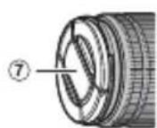
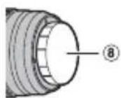
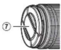
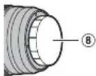
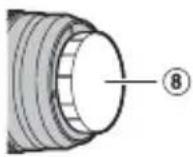
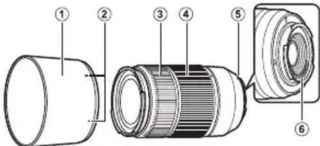
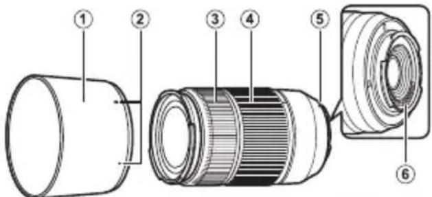
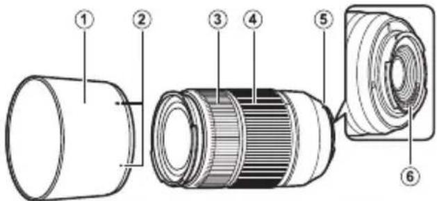
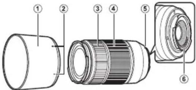
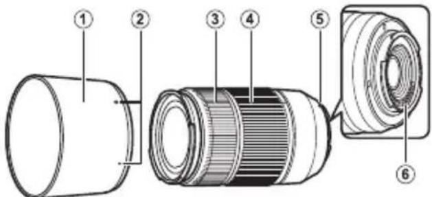
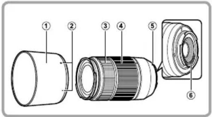
Parts of the Lens
XC16-50mmF3.5-5.6 OIS XC50-230mmF4.5-6.7 OIS
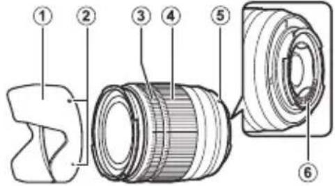

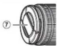
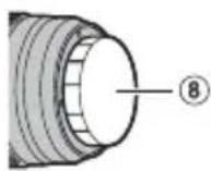
① Lens hood
② Mounting marks
③ Focus ring
④ Zoom ring
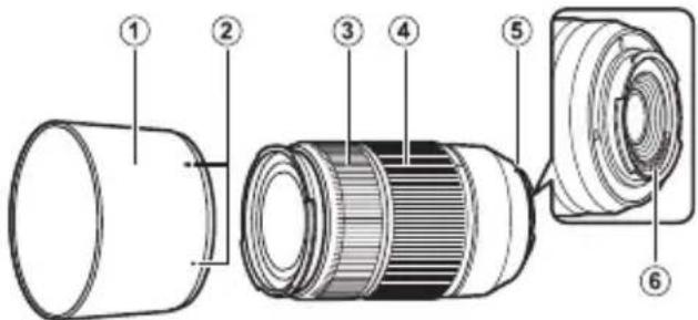
⑤ Mounting marks (focal length)
⑥ Lens signal contacts
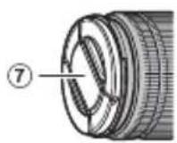
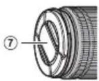
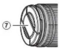
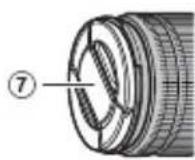
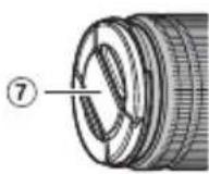
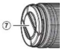
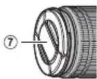
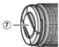
⑦ Front lens cap
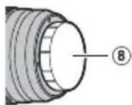
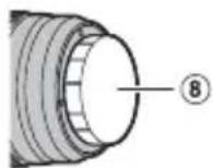
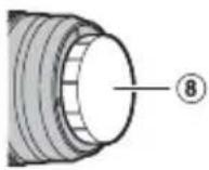
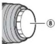
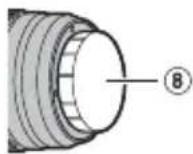
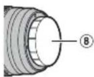
⑧ Rear lens cap
Supplied Accessories
- Front lens cap
- Rear lens cap
- Lens hood
ENGLISH
EN-5
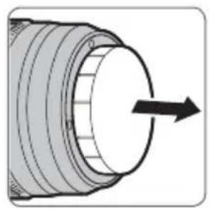
Attaching the Lens
See the camera manual for information on attaching and removing lenses. Note that this product is not compatible with X mount fi lm cameras.
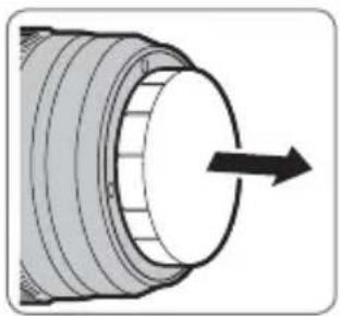
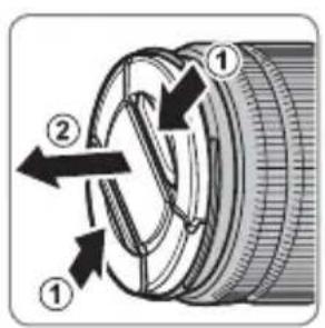
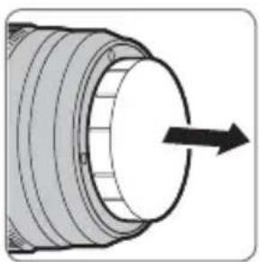
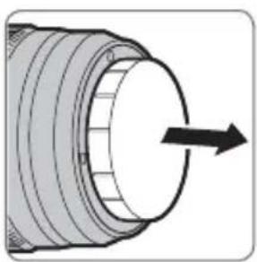
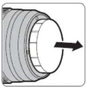
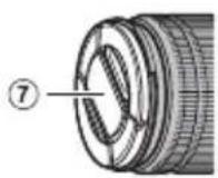
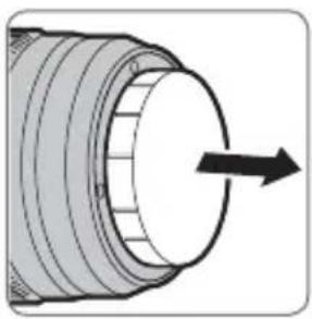
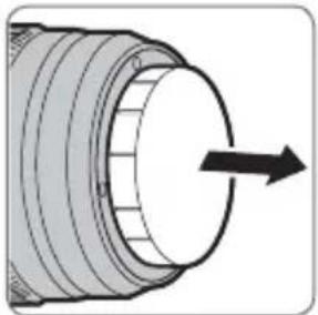
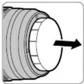
Removing the Caps
Remove the caps as shown.
natural_image
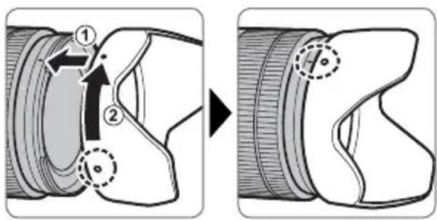
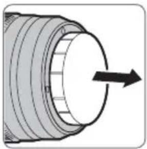
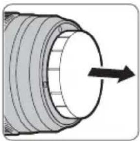
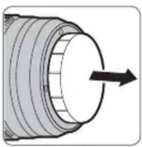
Cross-sectional diagram of a mechanical component with a circular arrow indicating direction (no text or symbols)Attaching the Hood
When attached, lens hoods reduce glare and protect the front lens element.
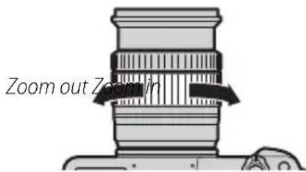
Zoom
Rotate the zoom ring left to zoom out, reducing magnifi cation and increasing the area visible in the frame. Rotate the ring right to zoom in, increasing magnifi cation so that the subject occupies more of the frame.
Optical Image Stabilization (OIS)
Optical image stabilization is available using the IS MODE option in the camera shooting menu.
Aperture
See the camera manual.
◆Users of the X-Pro1 and X-E1 should also read the document available online at the following URL:
http://www.fujifilm.com/support/digital_cameras/manuals/pdf/index/lens/before_using_this_product_manual_01.pdf
Specifications
| Type XC16-50mmF3.5-5.6 OIS XC50-230mmF4.5-6.7 OIS | ||
| Lens construction | 12 elements in 10 groups (includes 3 aspherical and 1 extra low dispersion elements) | 13 elements in 10 groups (incl aspherical and 1 extra low dispersion elements) |
| Focal length (35 mm format equivalent) | f=16–50 mm (24–76 mm) | f=50–230 mm (76–350 mm) |
| Angle of view 83.2°–31.7° 31.7°–7.1° | ||
| Max. aperture f/3.5–5.6 f/4.5–6.7 | ||
| Min. aperture f/22 | f/22 | |
| Aperture controlNumber of bladesStop size | 7 (rounded diaphragm opening)1⁄3 EV (17 stops) | 7 (rounded diaphragm opening)1⁄3 EV (15 stops) |
| Focus range | Normal: 0.6 m–infinity (zoom range)Macro: 30 cm–10 m (W); 40 cm–10 m (T) | Normal: 1.1 m–infinity (zoom range)Macro: 1.1 m–3 m |
| Max. magnification | T: 0.15 × | T: 0.2 × |
| External dimensions: Diameter × Length* (approx.)* distance from camera lens mount flange | W: ø62.6×65.2 mmT: ø62.6×98.3 mm | W: ø69.5×111 mmT: ø69.5×177 mm |
| Weight* (approx.)* excluding caps and hoods | 195 g | 375 g |
| Filter size | ø58 mm ø58 mm | |
① Improvements may result in unannounced changes to specifications and appearance.
① Owing to how this lens is constructed, the "Distance indicator" displayed by the camera may in some cases differ from the actual focus distance. Use the "Distance indicator" as a guide only.
EN-8 ENGLISH
Pour votre sécurité
http://www.fujifilm.com/support/digital_cameras/software/#firmware


Zoom
http://www.fujifilm.com/support/digital_cameras/manuals/pdf/index/lens/before_using_this_product_manual_01.pdf
http://www.fujifilm.com/support/digital_cameras/software/#firmware

natural_image
Cross-sectional diagram of a mechanical component with a circular shaft and threaded end, showing an arrow indicating direction (no text or symbols present)DE-6 DEUTSCH
http://www.fujifilm.com/support/digital_cameras/manuals/pdf/index/lens/before_using_this_product_manual_01.pdf
Technische Daten
http://www.fujifilm.com/support/digital_cameras/software/#firmware

natural_image
Cross-sectional diagram of a mechanical component with a circular arrow indicating direction (no text or symbols)ES-6 ESPAÑOL
Zoom
http://www.fujifilm.com/support/digital_cameras/manuals/pdf/index/lens/before_using_this_product_manual_01.pdf
http://www.fujifilm.com/support/digital_cameras/software/#firmware
① Zonnekap
② Bevestigingsmarkeringen
③ Scherpstelring
④ Zoomring

⑤ Bevestigingsmarkeringen (brandpuntsafstand)
⑥ Lenssignaalcontacten
⑦ Voorste lensdop
⑧ Achterste lensdop
Meegeleverde accessoires
- Voorste lensdop
- Achterste lensdop
• Zonnekap
NEDERLANDS
NL-5
Een lens bevestigen
De zonnekap bevestigen
NL-6 NEDERLANDS
Zoom
Optical Image Stabilization (OIS)
http://www.fujifilm.com/support/digital_cameras/manuals/pdf/index/lens/before_using_this_product_manual_01.pdf
Technische gegevens
| Type XC16-50mmF3.5-5.6 OIS XC50-230mmF4.5 | 6.7 OIS | |
| Lensconstructie 12 elementen in 10 groepen | (bevat 3 asferische en 1 extra lage dispersie elementen) | 13 elementen in 10 groepen (bevat 1 asferische en 1 extra lage dispersie elementen) |
| Brandpuntsafstand (equivalent aan 35 mm formaat) | f=16–50 mm (24–76 mm) | f=50–230 mm (76–350 mm) |
| Beeldhoek 83,2°–31,7° 31,7°–7,1° | ||
| Max. diafragma f/3,5–5,6 f/4,5–6,7 | ||
| Min. diafragma f/22 f/22 | ||
| Diafragmabesturing | ||
| Aantal bladen | 7 (ronde diafragmaopening) | 7 (ronde diafragmaopening) |
| Stopgrootte | 13 EV (17 stops) | 13 EV (15 stops) |
| Scherpstelbereik | Normaal: 0,6 m – ∞(zoombereik)Macro: 30 cm–10 m (W); 40 cm–10 m (T) | Normaal: 1,1 m – ∞(zoombereik)Macro: 1,1 m–3 m |
| Max. vergroting | T : 0,15 × | T : 0,2 × |
| Buitenafmetingen: Diameter × Lengte* (ongev.) * afstand vanaf bevestigingsflens van het objectief | W: 62,6 × 65,2 mmT : 62,6 × 98,3 mm | W: 69,5 × 111 mmT : 69,5 × 177 mm |
| Gewicht* (ongev.) * exclusief doppen en kappen | 195 g 375 g | |
| Filtergrootte | 58 mm 58 mm |
http://www.fujifilm.com/support/digital_cameras/software/#firmware
① Motljusskydd
② Monteringsmarkeringar
③ Fokusring
④ Zoomring
⑤Monteringsmarkeringar (brännvidd)
⑥Objektivsignalkontakter
⑦ Främre objektivlock
⑧ Bakre objektivlock
natural_image
Cross-sectional diagram of a mechanical component with a circular arrow indicating direction (no text or symbols)Zoom
http://www.fujifilm.com/support/digital_cameras/manuals/pdf/index/lens/before_using_this_product_manual_01.pdf
Specifi kationer
http://www.fujifilm.com/support/digital_cameras/software/#firmware


① Solblender
② Monteringsmerker
③ Fokusring
④ Zoomring
⑤ Monteringsmerker (brennvidde)
⑥ Objektivets signalkontakter
⑦ Fremre objektivdeksel
⑧ Bakre objektivdeksel
natural_image
Cross-sectional diagram of a mechanical component with a circular arrow indicating direction (no text or symbols)Zoom
Optisk bildestabilisering (OIS)
http://www.fujifilm.com/support/digital_cameras/manuals/pdf/index/lens/before_using_this_product_manual_01.pdf
Spesifi kasjoner
| Type XC16-50mmF3.5-5.6 OIS XC50-230mmF4.5 | 6.7 OIS | |
| Linsekonstruksjon | 12 elementer i 10 grupper (inkluderer 3 asfæriske og 1 ekstra lav spredningselementer) | 13 elementer i 10 grupper (inkluderer 1 asfæriske og 1 ekstra lav spredningselementer) |
| Brennvidde (35 mm format tilsvarende) | f=16–50 mm (24–76 mm) | f=50–230 mm (76–350 mm) |
| Bildevinkel 83,2°–31,7° 31,7°–7,1° | ||
| Største blenderåpning f/3,5–5,6 f/4,5–6,7 | ||
| Minste blenderåpning f/22 f/22 | ||
| Blenderåpningskontroll | ||
| Antall blader | 7 (avrundet blenderåpning) | 7 (avrundet blenderåpning) |
| Stoppstørrelse | 13 EV (17 stopp) | 13 EV (15 stopp) |
| Fokusrekkevidde | Normal: 0,6 m – (zoomområde)Macro: 30 cm–10 m (W); 40 cm–10 m (T) | Normal: 1,1 m – (zoomområde)Macro: 1,1 m–3 m |
| Maksimal forstørrelse | T : 0,15 × | T : 0,2 × |
| Utvendige dimensjoner:Diameter × Lengde* (ca.) * avstand fra kameraets objektivmonteringsflens | W: 62,6 × 65,2 mmT: 62,6 × 98,3 mm | W: 69,5 × 111 mmT: 69,5 × 177 mm |
| Vekt* (ca.) * ekskludert deksler og solblendere | 195 g | 375 g |
| Filter størrelse | 58 mm 58 mm |
http://www.fujifilm.com/support/digital_cameras/software/#firmware


natural_image
Cross-sectional diagram of a mechanical component with a circular arrow indicating direction (no text or symbols)Zoomaus
http://www.fujifilm.com/support/digital_cameras/manuals/pdf/index/lens/before_using_this_product_manual_01.pdf
Tekniset tiedot
http://www.fujifilm.com/support/digital_cameras/software/#firmware


natural_image
Cross-sectional diagram of a mechanical component with a circular shaft and arrow indicating direction (no text or symbols)Установка бленды
RU-6 РУССКИЙ
Масштабирование
http://www.fujifilm.com/support/digital_cameras/manuals/pdf/index/lens/before_using_this_product_manual_01.pdf
http://www.fujifilm.com/support/digital_cameras/software/#firmware

natural_image
Cross-sectional diagram of a mechanical component with a circular arrow indicating direction (no text or symbols)Montaggio paraluce
IT-6 ITALIANO
Zoom
http://www.fujifilm.com/support/digital_cameras/software/#firmware


Zoom
http://www.fujifilm.com/support/digital_cameras/manuals/pdf/index/lens/before_using_this_product_manual_01.pdf
Specifi kationer
http://www.fujifilm.com/support/digital_cameras/software/#firmware


natural_image
Cross-sectional diagram of a mechanical component with a circular arrow indicating direction (no text or symbols)PL-6 POLSKI
Zoom
http://www.fujifilm.com/support/digital_cameras/manuals/pdf/index/lens/before_using_this_product_manual_01.pdf
Dane techniczne
http://www.fujifilm.com/support/digital_cameras/software/#firmware
安装遮光罩
变焦
http://www.fujifilm.com/support/digital_cameras/manuals/pdf/index/lens/before_using_this_product_manual_01.pdf
中文简
ZHS-7
技术规格
http://www.fujifilm.com/support/digital_cameras/software/#firmware
natural_image
Cross-sectional diagram of a mechanical component with a circular shaft and threaded end (no text or symbols)安裝遮光罩
變焦
http://www.fujifilm.com/support/digital_cameras/manuals/pdf/index/lens/before_using_this_product_manual_01.pdf
規格
http://www.fujifilm.com/support/digital_cameras/software/#firmware
natural_image
Diagram of a mechanical component with a circular shaft and threaded end, showing an arrow indicating direction (no text or symbols present)후드부착
舌
http://www.fujifilm.com/support/digital_cameras/manuals/
pdf/index/lens/before_using_this_product_manual_01.pdf
الزوم
تركيب العدسة
natural_image
Cross-sectional diagram of a mechanical component with a circular shaft and arrow indicating direction (no text or symbols)أجزاء العدسة
الإكسوارات المرفقة
• واقية العدسة
• الأمامي
• الخلفي
عربي
AR-5

- レンズフードの取り付け方
- ズーム操作
- Be sure to read these notes before use
- Safety Notes
- About the Icons
- WARNING
- CAUTION
- For Customers in the U.S.A.
- Tested To Comply With FCC Standards FOR HOME OR OFFICE USE
- For Customers in Canada
- IMPORTANT SAFETY INSTRUCTIONS
- Disposal of Electrical and Electronic Equipment in Private Households
- Australian C-Tick
- Before Using This Product
- Product Care
- Parts of the Lens
- Supplied Accessories
- Attaching the Lens
- Removing the Caps
- Attaching the Hood
- Zoom
- Optical Image Stabilization (OIS)
- Aperture
- Pour votre sécurité
- Meegeleverde accessoires
- Een lens bevestigen
- De zonnekap bevestigen
- Optisk bildestabilisering (OIS)
- Zoomaus
- Установка бленды
- Масштабирование
- Montaggio paraluce
- 安装遮光罩
- 变焦
- 安裝遮光罩
- 變焦
- 후드부착
- 舌
- الزوم
- تركيب العدسة
Brand : FUJIFILM
Model : XC50230mmF4.56.7 OIS
Category : Lens