BTS 4000 - Sander Güde - Free user manual and instructions
Find the device manual for free BTS 4000 Güde in PDF.
Download the instructions for your Sander in PDF format for free! Find your manual BTS 4000 - Güde and take your electronic device back in hand. On this page are published all the documents necessary for the use of your device. BTS 4000 by Güde.
USER MANUAL BTS 4000 Güde
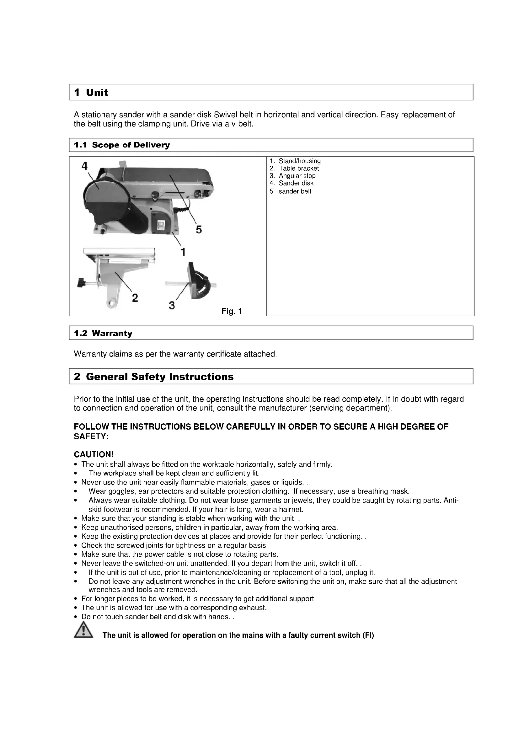
1.1 Scope of Delivery
Warranty claims as per the warranty certificate attached. 2 General Safety Instructions Prior to the initial use of the unit, the operating instructions should be read completely. If in doubt with regard to connection and operation of the unit, consult the manufacturer (servicing department). FOLLOW THE INSTRUCTIONS BELOW CAREFULLY IN ORDER TO SECURE A HIGH DEGREE OF SAFETY: CAUTION!
- The unit shall always be fitted on the worktable horizontally, safely and firmly.
The workplace shall be kept clean and sufficiently lit. .
- Never use the unit near easily flammable materials, gases or liquids. .
- Wear goggles, ear protectors and suitable protection clothing. If necessary, use a breathing mask. .
- Always wear suitable clothing. Do not wear loose garments or jewels, they could be caught by rotating parts. Anti- skid footwear is recommended. If your hair is long, wear a hairnet.
- Make sure that your standing is stable when working with the unit. .
- Keep unauthorised persons, children in particular, away from the working area.
- Keep the existing protection devices at places and provide for their perfect functioning. .
- Check the screwed joints for tightness on a regular basis.
- Make sure that the power cable is not close to rotating parts.
- Never leave the switched-on unit unattended. If you depart from the unit, switch it off. .
- If the unit is out of use, prior to maintenance/cleaning or replacement of a tool, unplug it.
- Do not leave any adjustment wrenches in the unit. Before switching the unit on, make sure that all the adjustment wrenches and tools are removed.
- For longer pieces to be worked, it is necessary to get additional support.
- The unit is allowed for use with a corresponding exhaust.
- Do not touch sander belt and disk with hands. . The unit is allowed for operation on the mains with a faulty current switch (FI)2.1 Emergency Action Apply the first aid adequate to the injury and get qualified medical assistance as quickly as possible. Protect the injured person from more accidents and calm him/her down.
Meaning of Symbols Symbols shown below are used throughout this manual and/or on the unit: Product Safety Product compliance with respective EU standards Bans: General ban (combined with another pictograph No fire, no open fire and no smoking Do not touch Do not reach in the rotating parts Do not use the unit in rain Warning Warning/Caution Beware of hazardous voltage Keep at safe distance Commands Wear goggles Wear ear protectors Use protection gloves Wear breathing mask Unplug before opening Read instruction manual before use Environment Protection: Wastes to be disposed of in a professional manner not to harm the environment. Cardboard packaging to be collected for recycling. Faulty and/or disposed of electrical/electronic appliances to be collected by authorised salvage places.Packaging: Keep away from moisture The package should be held upwards Fragile Technical Data Motor power Connection Speed rpm Sand belt dimensions Sander disk dimensions Weight Acoustic output level
The unit should be used for grinding/sanding and working of wood pieces only. The manufacturer should not be held liable for any personal and material losses due to a failure to observe these rules.
2.4 Residual Hazards and Protective Action
2.4.1 Mechanical Residual Hazards
Hazard Description Protective Action Residual Hazards Catching, winding Lose garments and jewels may be caught with moving parts Always wear tight-fitting garments and do not wear jewels that might be caught. Friction, abrasion Contact with rotating sander disk may result in serious injuries. Avoid any contact with the sanding means. Use protection gloves.
2.4.2 Electrical Residual Hazards
Hazard Description Protective Action Residual Hazards Direct electrical contact Indirect electrical contact t Defective cable or plug may cause an electrical shock. Accidents caused by conductive parts on open or defective structural parts. Have the defective cable/plug exchanged by a professional. Use the unit only if connected via a faulty current switch (FI). Always unplug for maintenance Use the unit only if connected via a faulty current switch (FI).2.4.3 Noise Hazard Hazard Description Protective Action Residual Hazards Hearing Impairment Prolonged work with the unit may result in hearing impairment. Wear ear protectors
2.4.4 Materials and Other Substances Hazards
Hazard Description Protective Action Residual Hazards Contact, aspiration Lungs may be affected by great amount of dust being formed.
Always wear breathing mask when working with the unit.
2.4.5 Human Factor Neglect
Hazard Description Protective Action Residual Hazards Neglect us of personal protection equipment Operating the unit without adequate PPE may cause severe external/internal injuries Always wear prescribed protective clothing and work considerately. Inadequate local lighting Insufficient light is a heavy safety risk. Provide for sufficient lighting
Hazard Description Protective Action Residual Hazards Thrown away objects and splashes In the process of cutting, the blade or mechanical particles may injure your eyes. Always wear goggles when working with the unit
Disposal instructions are given by pictographs on the unit or packaging. For meaning of individual symbols refer to chapter “Symbols on Unit”.
2.5 Operator Requirement
The operator shall read the instruction manual carefully before using the unit.
No special qualification is required for use of the unit except for detailed direction by a professional.
Only persons above 16 years of age are allowed to work with the unit. . Exempted from the provision is the use of the juvenile trainees if they work in the course of their professional training with an aim to obtain the skill under a trainer supervision.
Use of the unit requires adequate lesson by a professional or the use of the manual only. Special training is not required.3 Technical Data Supply connection 230 V Frequency/Protection type 50 Hz / IP 20 Protection class
Work area l x w: 225 x 165 mm Ø sander disk ca: 152 mm Sander belt dimensions l x w: 910 x 100 mm Stop inclination: 0-45° Sander belt inclination : 0-90° Connection cable: 2 m / H05 VV-F Weight ca: 13 kg Dimensions l x w x h (mm): 570 x 260 x 340 mm Ordering No.: 55113 4 Transportation and Storage The unit has been designed for stationary use. Units out of use should be stored in a dry locked room. . 5 Assembly and Initial Operation Structural Group 1 Delivery-contained parts and accessories Fig. 2 Structural Group 2 Required structural groups Delivered parts and accessories Fig. 3 Structural group 1 Fig. 1– Pos. 2 Structural Group 3 Required structural groups Delivered parts and accessories Fig. 4 Structural group 2 Fig. 1 – Pos. 3Fig. 5 The unit has to be operated with dust exhaust. Firstly, that will prevent dust nuisance and secondly, it helps to achieve better sanding results. Fig. 6 Mount the unit to 4 prepared holes on flat horizontal surface using matching screws and check it for tight support.
5.1 Alternative Table Assembly
Structural Group 4 Required structural groups Delivered parts and accessories Fig. 7 Assembly rod of
ructural group 1 Structural Group 5 Required structural groups Delivered parts and accessories Fig. 8 Structural group 4 Structural Group 6 Required structural groups Delivered parts and accessories Fig. 9 Structural group 5Structural Group 7 Required structural groups Delivered parts and accessories Fig. 10 Structural group 6 Structural Group 8 Required structural groups Delivered parts and accessories Fig. 11 Structural group 7 Fig. 1 – Pos. 2
5.2 Initial Operation Safety Instructions
- Mind the safe attachment of the unit on a suitable surface area.
- Make sure that all the screwed joints are tight.
- The assembly of parts should be done in shown order. Be particular about correct arrangements of structural parts according to the figures.
- Connect a suitable dust exhauster to the exhaust connection. The unit must always be operated with a dust exhauster. That will prevent excessive dust nuisance that may be health hazardous and helps to a better sending result. 6 Operation Fig. 12 Mind the rotation direction! Fig. 13 By pressing button (I), the unit will switch on. Pressing
tton (0), it will switch off.6.1 Operator Safety Instructions Unplug before any maintenance, adjustment and cleaning. Unplug, having finished the work.
- Do not use the machine until you have read the instruction manual carefully.
- Observe any safety instructions included in the manual.
- Be responsible to the others
6.2 Step-by-Step Instructions
1. Switch on the unit and work the piece either on the sander belt or the sander disk. (Never work it against
the rotation direction)
2. Switch the unit off and clean it.
7 Troubles – Causes – Troubleshooting CAUTION: ALWAYS CHECK THE THERMAL FUSE FIRST! Trouble Cause Troubleshooting Burnt wood.
1. Blunt belt or disk. 1. Replace the belt/disk.
(see Sander belt replacement ) Belt running sideward.
1. Set-up does not match. 1. Set-up the belt again
(see Sander belt replacement ) Belt will not start up.
1. Belt too tensioned 1. Loosen the belt.
8 Inspections and Maintenance Unplug before any maintenance, adjustment and cleaning. Unplug, having finished the work.
8.1 Sander Belt Replacement
Fig. 14 Unscrew the marked screws and remove lower cover,
otection back plate and the stop.Fig. 15 Shift the tension clamp in the direction of the arrow, loosening this sander belt. With all the covers removed, it is possible to take off the sander belt and replace it with a new one. Stretch the sander belt, pushing the tension lever in the opposite direction as far as to the stop. Fig. 16 The sander belt track may be set up using the setting scr ew. To do that, switch the unit on and turn the setting screw until the sander belt runs centred in relation to the shaft. . Fig. 17 The unit will switch on by pressing button (I). Pressing button (0), it will switch off.
8.2 Inspections and Maintenance Safety Instructions
The machine will serve as a sufficient aid only if maintained and care for appropriately. Insufficient maintenance and care may result in accidents and injuries.