
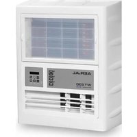
AD 740 - Dehumidifier Aerial - Free user manual and instructions
Find the device manual for free AD 740 Aerial in PDF.

| Brand | Aerial |
| Model | AD 740 |
| Product type | Dehumidifier |
| Power supply | 230 V / 50 Hz, 625 W, 3.5 A |
| Refrigerant | R454c (0.32 kg, GWP 148) |
| Dehumidification capacity | Not specified in the manual |
| Water tank (bucket) | Integrated, with locking and full bucket indicator |
| Continuous drainage possible | Yes, via an optional drain hose (12 x 2 mm) |
| Main functions | Automatic dehumidification, automatic defrost, night mode (10 h at low level), power meter (MID), key lock, language setting |
| Control panel | Screen, adjustment keys (humidity, ventilation, information, on/off) |
| Ventilation levels | 2 levels (high and low performance) |
| Operating temperature range | Approximately 5 °C to 30 °C (error messages outside range) |
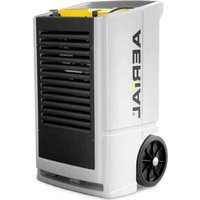
| Stacking | Up to 2 units, with strap fixation |
| Transport | Folding handle and 2 wheels (AD 740), vertical transport |
| Cleaning and maintenance | Washable air filter (or replacement), wipeable drip tray, drain pan (AD 40) |
| Spare parts and repairability | Original filters, AERIAL after-sales service, repairs by qualified personnel |
| Safety | Flammable refrigerant (R454c), do not use in explosive atmospheres, IP X1 protection, automatic stop in case of full bucket |
| Dimensions (approx.) | Not specified in the manual |
| Weight (approx.) | Not specified in the manual |
Frequently Asked Questions - AD 740 Aerial
User questions about AD 740 Aerial
0 question about this device. Answer the ones you know or ask your own.
Ask a new question about this device
Download the instructions for your Dehumidifier in PDF format for free! Find your manual AD 740 - Aerial and take your electronic device back in hand. On this page are published all the documents necessary for the use of your device. AD 740 by Aerial.
USER MANUAL AD 740 Aerial
natural_image
Front view of a white industrial air purifier with visible cooling fans and wheels (no text or symbols)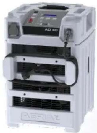
natural_image
Exterior view of a white industrial device labeled 'AD 40' with visible internal components and ventilation ducts (no readable text beyond branding)AD 740
AD 40
EN Operating Instructions 14
FI Käyttöohje
natural_image
Interior view of a rectangular electronic device casing with a labeled component (no text or symbols beyond the number 5)Fig. 2: Rückansicht
natural_image
Close-up of a server rack with ventilation grilles and a black cable labeled '1' (no visible text or symbols on the device itself)natural_image
Interior view of a computer case with a black arrow pointing to a component labeled '2' (no text or symbols on the main body)natural_image
Close-up of a hand opening a black plastic door with a small object inside, next to a white panel (no visible text or symbols)natural_image
Interior view of an electric air conditioning unit with cooling fins and a hand placed on the side (no visible text or symbols)natural_image
Hand holding a dark textured surface with a black arrow pointing to a numbered label '6' (no readable text or symbols on the surface)1 Models 14
2 Product overview....15
3 Overview of control panel 16
4 About these operating instructions .... 17
5 Product description....17
6 Safety 17
7 Unpacking 18
8 Stacking appliances 18
9 Transport and connection....18
10 Operation....20
11 Maintenance and care 21
12 Troubleshooting.... 22
13 Decommissioning, storage and disposal 23
14 EC Declaration of Conformity 24
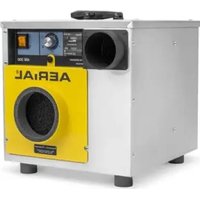
1 Models
These operating instructions relate to various models. The functions and operation are virtually identical. You can find out which model you have from the identification plate. Further information can be found in the Technical Data (see last page).
Model Main characteristics
| AD 740 Hinged handle, 2 wheels | |
| AD 40 | Carry handles, feet |
2 Product overview
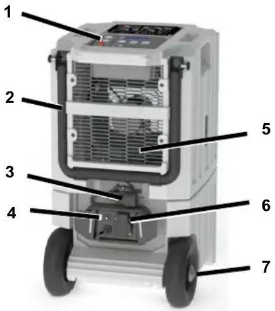
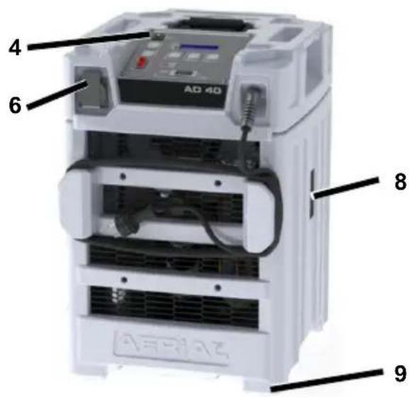
Fig. 1: Front view
| 1 | Control panel | 6 | Socket |
| 2 | Hinged handle (AD 740 only) | 7 | Wheels (AD 740) |
| 3 | Mains plug 8 Attachment points for safety harnesses | ||
| 4 | Socket fuse 9 Feet (AD 40) | ||
| 5 | Air outlet | ||
natural_image
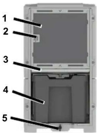
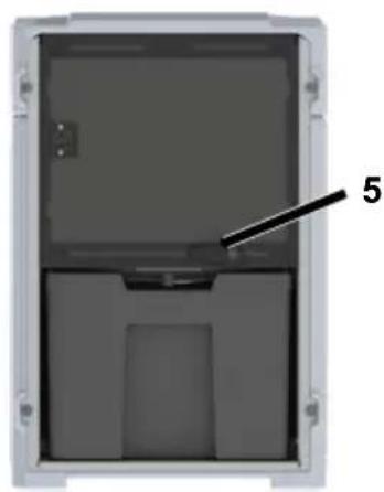
Interior view of a rectangular electronic device casing with a labeled component (no text or symbols beyond the number 5)Fig. 2: Back view
| 1 | Air intake area with filter | 4 | Basin |
| 2 | Ambient temperature sensor | 5 | Basin lock |
| 3 | Drip tray |
3 Overview of control panel

Fig. 3: Overview of control panel
| 1 | Actual room humidity | 7 | Load counter (MID) |
| 2 | Increase room humidity | 8 | “Basin full” indicator |
| 3 | Target room humidity | 9 | Info key |
| 4 | Lower room humidity | 10 | Night mode |
| 5 | Fan setting | 11 | Operating hours |
| 6 | On/off button 12 Display |
| Button | Press briefly | Press for 5s | Display |
 | Lower/raise room humidity in 1% incrementsFrom the Language menu: Select language | Lower/increase room humidity in 5% increments | |
 | |||
| On/off button | Switch dehumidifier on/off | Start45% 12345h | |
 | Change fan levelsLevel 2: Higher fan powerLevel 1: Lower fan power | fan speed highfan speed low | |
 | Press twice briefly: Setting the language | Unlock key lock | Language English |
4 About these operating instructions
These operating instructions must not be reproduced, duplicated or distributed without the written consent of the manufacturer.
Important: Read carefully before use. Keep for later reference.
5 Product description
The dehumidifier controls the air humidity in the room. The condensate water produced is collected in a basin or pumped away via an optional discharge hose. The dehumidifier has an automatic defrost function.
Package contents
- Dehumidifier
- Operating instructions
- Basin (in appliance)
Optional accessories
- Pump kit
- Discharge hose
Identification plate
The identification plate is on the basin.
6 Safety
Intended use and conditions of use
The dehumidifier is used to remove humidity from air where there is atmospheric pressure in closed indoor rooms, such as basements, garages or warehouses.
The dehumidifier must only be set up, used and stored in rooms with larger than 4 m2 .
The dehumidifier must only be used in compliance with the Technical Data (see last page).
Persons with physical, sensory or mental restrictions and children are not permitted to use the dehumidifier.
Every user must have read and understood the operating instructions.
Foreseeable misuse
The dehumidifier must not be used:
- In rooms with potentially explosive atmospheres.
- In rooms with an aggressive atmosphere (e.g. caused by chemicals).
- In rooms with water with a pH value below 7.0 or above 7.4.
- In rooms with salt or liquids with a salt content > 1 %, e.g. brine baths.
- In wet areas of indoor swimming pools.
- In rooms with ozone-treated air, high solvent concentrations or high dust pollution.
General safety information
WARNING! Risk of explosion, burns and poisoning from refrigerants!
The appliance contains an odourless, flammable refrigerant which, if handled incorrectly, could result in explosions and fire as well as injuries and burns. The refrigerant circuit is pressurised.
Do not use any objects to accelerate the thawing process.
Do not store the dehumidifier in rooms with permanent sources of ignition, such as open flames, operational gas appliances or electric heaters.
Do not drill open or ignite dehumidifiers.
- Only operate the appliance in an adequately ventilated room larger than 4 m 2 .
- Any work to the refrigerant circuit must be performed by the manufacturer or the manufacturer's authorised technical personnel. Before working on the refrigerant circuit, it must be depressurised using the designated mechanisms.
- Observe the national regulations for gas installations.
Do not dump refrigerants or dispose of them as household waste.
Avoid coming into contact with the refrigerant.
WARNING! Electrocution!
Working on live components or water on live components can cause life-threatening electrocution.
Avoid contact between water and live components.
Always switch off and unplug the dehumidifier and drain away any water before moving it to another location.
Always empty the basin before moving it to another location.
- Only allow the manufacturer or authorised personnel to carry out work on electric components.
7 Unpacking
Procedure
- Check that the package contents are complete. Contact your stockist in the event of damage or missing contents.
- Remove the packaging and dispose of it in accordance with local regulations.
8 Stacking appliances
Two appliances from this series can be stacked on top of each other for transport and storage.
Warning! Crushing as a result of tipping or instability!
Do not stack more than two dehumidifiers on top of each other. Make sure that the feet of the top appliance are in the notches of the bottom appliance.
➢ Secure the dehumidifiers to prevent them from tipping over or falling, e.g. using tension belts.
Procedure
- Place the feet of the top appliance in the appropriate notches of the bottom appliance.
- Attach a suitable safeguard, e.g. tension belts, to the attachment points for straps to secure the top appliance to the bottom appliance and stop it from falling off. Stack a maximum of two appliances.
9 Transport and connection
Transport
WARNING! Crushing as a result of instability!
- Transport the dehumidifier in an upright position and secure it so that it cannot tip over or slip.
Position the dehumidifier on a stable, even surface.
WARNING! Crushing or cutting from reaching into the grille of the air filter!
- Use the handles to transport the dehumidifier.
Do not reach into the air filter.
CAUTION! Crushing or ergonomic damage when transporting the dehumidifier!
- Use the handles to transport the de-humidifier.
The dehumidifier must be transported by two people.
Procedure
- Make sure that the basin is empty and secured with the basin lock.
- Make sure that the discharge hose (optional) and the mains cable have been disconnected from the appliance.
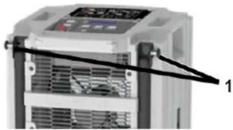
- AD 740: Raise the hinged handle for transporting on the wheels. To do this, release the lock on the right and left of the hinged handle (item 1) and lift the hinged handle until the lock engages again.
natural_image
Close-up of a server rack with ventilation grilles and a black cable labeled '1' pointing to a component (no readable text or symbols beyond label)- Transport the dehumidifier to where it is going to be used.
- AD 740: Fold the hinged handle back down again.
NOTE: The air must circulate freely. Do not cover the air openings. There must be a clearance of at least 1 m in front of the air outlet and the air filter.
Preparing the basin
Does not apply if an optional discharge hose is connected.
Procedure
➢ Slide the basin into the dehumidifier.
- Secure the basin with the basin lock.
Connecting an optional discharge hose
If necessary, the condensate water can be drained off via a discharge hose instead of into the basin. To do this, proceed as follows:
ATTENTION! Inadequate appliance output!
Do not place the end of the hose in the water (backwater possible).
Do not bend the discharge hose.
Do not place any objects on the hose.
Procedure
- Remove the basin.
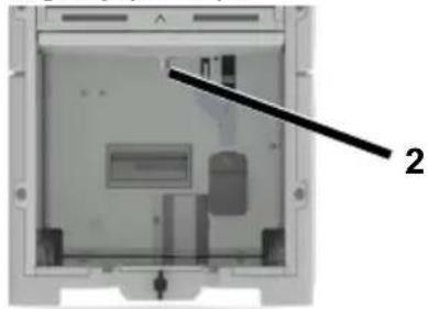
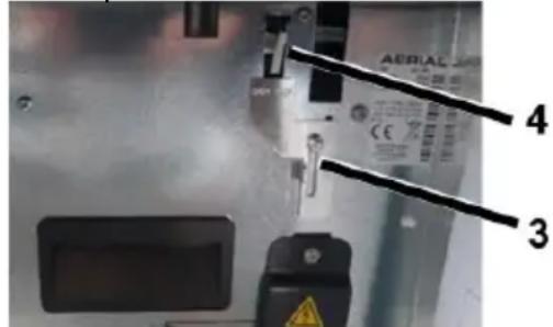
- Attach a suitable hose (12 x 2 mm) to the discharge nozzle (Pos. 2) using a pipe clip.
natural_image
Interior view of a computer case with labeled component (no text or symbols visible)- Make sure that the end of the hose is lower than the start of the hose at the discharge nozzle. Minimum slope of 5 % (5 cm/metre).
- Slide the top cover sheet (item 3) in front of the notch (item 4). To do this, loosen the screw on the cover sheet and slide the cover sheet to the top.
- Run the end of the hose into a drain or a suitable container.
Electrical connection
Procedure
- Make sure that the supply voltage is the same as the connection voltage in the technical data.
- Provide an adequate fuse for the socket and the power supply.
- Install an earth leakage circuit breaker in damp rooms and building sites.
- Make sure that the mains plug is suitable for the socket of the building.
- Make sure that the socket used is earthed.
- Plug the mains plug into the socket.
- If necessary, connect one more appliance at most to the socket on the dehumidifier. If more than one appliance is connected, the integrated socket fuse will stop the appliances from working.
10 Operation
Unlock key lock
The key lock activates automatically if the control panel is inactive for 2 minutes.
Procedure
- Hold the ⓘ key down for 5 seconds.
The key lock is released.
Setting the language
Procedure
- Press the Ⓐ key twice in quick succession.
- The display will show the current language.
- Set the desired language using the arrow keys ▼ ▲
- Wait 3 seconds until the selected language stops flashing.
Dehumidifying the room
NOTE: Allow the dehumidifier to rest in its final position for approx. 15 minutes before starting up, after transport and after prolonged storage.
Procedure
- Make sure that the condensate water can drain off through a discharge hose or into the basin.
- Set on/off button to "I".
"Start" will flash in the display. The dehumidifier will start operating. Operation is not possible when "Stop" or "Start" is flashing.
- Set the desired humidity using the
arrow keys . The dehumidifier will only start if the actual room humidity is higher than the target room humidity.
- Select the fan level. To do this,
press the key.
The dehumidifier runs until the target room humidity has been reached or the basin is full, then it will stop running.
Emptying the basin
The "Basin full" indicator flashes, the basin is full.
Procedure
- Release the basin lock.
- Empty the basin.
- Secure the basin again with the basin lock.
Night mode
If necessary, night mode can be enabled for quieter operation for 10 hours.
- Press the key.
The dehumidifier runs for 10 hours at level 1.
Switching off
Procedure
- Empty basin if necessary.
- Set on/off button to "0".
11 Maintenance and care
WARNING! Electrocution!
➢ Always disconnect the mains plug to disconnect the dehumidifier from the power supply before cleaning the defrosting tray of the AD40.
WARNING! Damage to health from dust!
- Only clean the dehumidifier with compressed air in open spaces.
- Wear a protective mask and goggles.
ATTENTION! Damage to property!
Cleaning agents can damage surfaces. Only use mild detergents.
- Only use approved original spare parts.
Cleaning and inspection
Procedure
- Switch off the dehumidifier.
- Unplug the mains plug.
- Remove and clean the air filter (e.g. with vacuum cleaner) or replace it.
- Check the discharge nozzle and discharge hose, if connected.
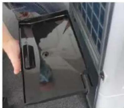
- AD 740 only: Pull out the drip tray slightly and wipe with a cloth.
natural_image
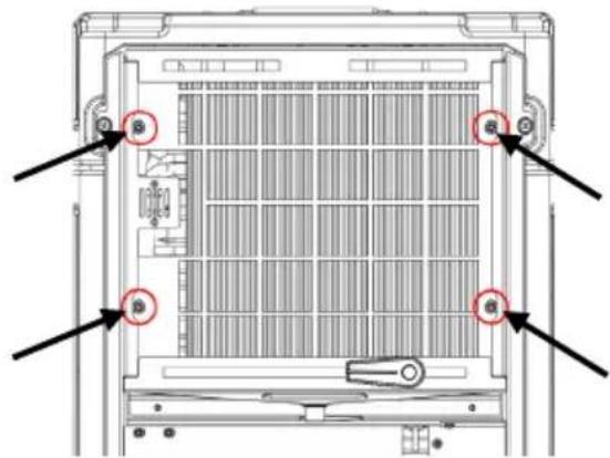
Close-up of a hand opening a black plastic door with a small inset showing a white object, next to a white panel (no visible text or symbols)- AD 40 only: Remove the filter holder. To do this, undo the four marked screws with a suitable screwdriver and remove the filter holder.
natural_image
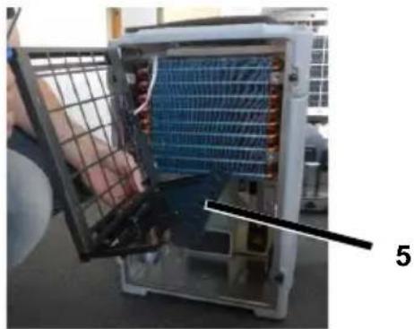
Technical diagram of a server rack with mounting points and internal grid structure (no text or symbols)- Nur AD 40: The drip tray is on the filter cover (item 5). Wipe the drip tray with a cloth.
natural_image
Interior view of an electric air conditioning unit with visible cooling fins and a hand inserting a cable (no text or symbols)- Insert/push in the drip tray again and fit the filter cover again if necessary.
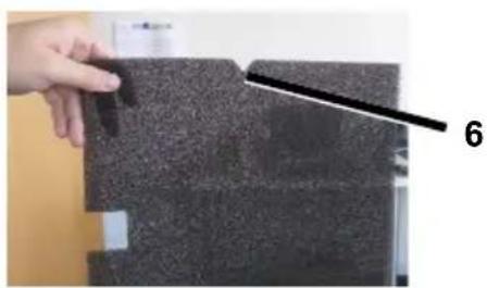
Insert a new or clean filter. Only use an original filter. Make sure that the notch (item 6) is facing up.
natural_image
Hand holding a dark textured surface with a black line and number 6 pointing to it (no text or symbols on the surface)-
Plug in the mains cable.
-
Switch on the dehumidifier if necessary.
Spare parts and customer service
If you have any questions about the de-humidifier or require spare parts, contact your authorised dealer or AERIAL Service.
12 Troubleshooting
Please check the following points in the event of a fault. If necessary contact AERIAL Service.
WARNING! Poisoning from refrigerant, burns, crushing or electrocution during maintenance work!
- Only allow the manufacturer or authorised personnel to carry out repairs and maintenance work.
In the event of malfunctions, switch off the dehumidifier and secure it so that it cannot be switched back on again.
Allow any hot components to cool sufficiently before working on them.
Error messages
| Display message | Possible cause | Remedial action |
| Error E1<Room temp> | Outside temperature < 1 °C or >34°C | Appliance will automatically re-start as soon as the temperature is >5 °C or< 30 °C. |
| Error E2<cooling system> | Cooling system fault Check filter and clean/replace if necessary.Check air intake area and air outlet. Both must be freely accessible. | |
| Faulty refrigeration circuit | Contact AERIAL Service. | |
Faults
| Problem | Possible cause | Remedial action |
| The dehumidifier is not performing well/removing moisture. | Air filter is dirty. The dehumidifier is not getting enough air. Dirty filters can damage the appliance in the long term. | Clean the filter or replace if necessary. |
| The dehumidifier is out of operation / fan and compressor are not working. | Dehumidifier is switched off. | Switch on the dehumidifier. |
| There is no power supply to the dehumidifier. | Check the power supply. | |
| “Basin full” illuminates even though the basin is empty. | Basin not inserted correctly. | Insert basin correctly. |
| Pump fault. Pump is blocked, e.g. water cannot drain out of the discharge hose/basin. | Check the discharge hose/basin, if connected. | |
13 Decommissioning, storage and disposal
Decommissioning
Procedure
- Switch off the dehumidifier.
- Empty the basin.
- Unplug the mains plug.
- Cover the dehumidifier with a cloth to protect it from dust.
Secure the dehumidifiers to prevent them from tipping over or falling, e.g. using tension belts.
Procedure
- Store the dehumidifier between 0 °C and +40 °C.
Storage
WARNING! Injury!
Do not stack more than two dehumidifiers on top of each other. Make sure that the feet of the top appliance are in the notches of the bottom appliance.
Disposal
ATTENTION! Risk from materials and substances
Sort materials according to type and recycle in accordance with local regulations.
When disposing of auxiliary and operating materials, observe the local regulations and information on the safety data sheets.
Do not dispose of the de-humidifier as household waste but rather in accordance with the legal regulations.
14 EC Declaration of Conformity
EC Declaration of Conformity in accordance with Machinery Directive 2006/42/EC Appendix II 1.A
Functional description: The dehumidifier is used to remove humidity from air where there is atmospheric pressure in closed rooms.
We hereby confirm that the product complies with the relevant provisions of the following directives:
• 2006/42/EC Machinery directive
• 2014/30/EU Directive on electromagnetic compatibility (EMC)
The following harmonised standards have been applied:
• EN 60335-2-40:2003
• EN 60335-1:2012
• EN 60204-1:2018
• EN 378-2:2016
• EN ISO 12100:2010
• EN ISO 13857:2008
• EN ISO 14120:2015
Person authorised to compile the technical documentation: Manfred Föhlisch - Oststraße 148 - 22844 Norderstedt
Norderstedt, 30/11/2020
natural_image
Interior view of a rectangular electronic device casing with a labeled component (no text or symbols beyond the number 5)Fig. 2: Taustapuoli
natural_image
Close-up of a server rack unit with ventilation grilles and a black cable labeled '1' pointing to a component (no readable text or symbols beyond label)natural_image
Interior view of a computer case with labeled component '2' (no text or symbols on the casing itself)natural_image
Close-up of a hand holding a black plastic tray with a small inset showing a white object, next to a white panel (no visible text or symbols)natural_image
Technical diagram of a server rack with labeled components and directional arrows (no text or symbols present)natural_image
Interior view of an open industrial cooling unit with visible cooling fins and a hand holding the panel (no text or symbols)natural_image
Close-up of a hand holding a textured black surface with a black line and number 6 pointing to it (no text or symbols on the surface itself)natural_image
Interior view of a rectangular electronic device casing with a labeled component (no text or symbols beyond the number 5)Fig. 2: Vista posteriore
natural_image
Close-up of a server rack unit with ventilation grilles and a black cable labeled '1' (no readable text or symbols beyond label)natural_image
Interior view of a computer case with labeled component (no text or symbols visible)natural_image
Close-up of a hand opening a black plastic door with visible internal components (no text or symbols)natural_image
Technical diagram of a server rack with mounting holes and ventilation grilles (no text or labels)natural_image
Interior view of an electric air conditioning unit with visible cooling fins and internal grid structure (no text or symbols)natural_image
Hand holding a dark textured surface with a black arrow pointing to a small object, labeled '6' (no text or symbols on the main subject)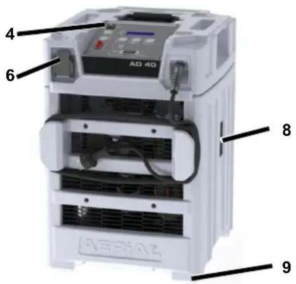
natural_image
Interior view of a rectangular electronic device casing with a labeled component (no text or symbols visible)Fig. 2: vue arrière
9 Transport et raccordement
Transport
natural_image
Close-up of a server rack unit with ventilation grilles and a black cable labeled '1' (no visible text or symbols on the device itself)natural_image
Interior view of a computer case with labeled component '2' (no text or symbols on the device itself)natural_image
Close-up of a hand opening a black plastic door with a small inset showing a device, next to a white panel (no visible text or symbols)natural_image
Technical line drawing of a server rack with mounting holes and ventilation grilles (no text or symbols)natural_image
Interior view of an air conditioning unit with visible cooling panel and mesh casing (no text or symbols)natural_image
Close-up of a hand holding a dark textured surface with a black arrow pointing to a numbered label '6' (no text or symbols on the surface itself)natural_image
Interior view of a rectangular electronic device casing with a labeled component (no text or symbols beyond the number 5)Fig. 2: Set bagfra
| 1 | Luftindtag med filter | 4 | Beholder |
| 2 | Rumluftføler 5 Beholderlås | ||
| 3 | Afdrypningsbakke |
3 Oversigt over betjeningspanel
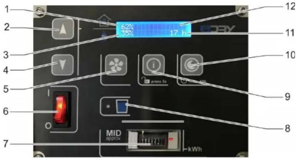
Fig. 3: Oversigt over betjeningspanel
natural_image
Close-up of a server rack unit with ventilation grilles and a black cable labeled '1' (no visible text or symbols on the device itself)natural_image
Interior view of a computer case with labeled component '2' (no text or symbols on the diagram itself)natural_image
Close-up of a hand opening a black plastic door with a small inset showing a circular object, next to a white panel (no visible text or symbols)natural_image
Technical diagram of a server rack with mounting holes and internal grid structure (no text or labels)- Nur AD 40: Afdrypningsbakken sidder på filterafdækningen (pos. 5). Tør afdrypningsbakken af med en klud.

natural_image
Interior view of an electronic device showing a grid-patterned panel and internal components (no visible text or symbols)natural_image
Close-up of a hand holding a dark textured surface with a black arrow pointing to a numbered label '6' (no readable text or symbols on the surface)natural_image
Interior view of a rectangular electronic device casing with a labeled component (no text or symbols beyond the number 5)Fig. 2: Sett bakfra
natural_image
Close-up of a server rack with ventilation grilles and a black cable labeled '1' (no visible text or symbols on the rack itself)natural_image
Interior view of a computer case with labeled component '2' (no text or symbols on the device itself)natural_image
Close-up of a hand opening a black plastic door with a small bottle, next to a white panel (no visible text or symbols)- Kun AD 40: Dryppannen (pos. 5) befinner seg ved filterdekselet. Tørk dryppannen med en klut.

natural_image
Interior view of an electric air conditioning unit with visible cooling fins and battery (no text or symbols)natural_image
Close-up of a hand holding a dark textured surface with a black arrow pointing to a numbered label '6' (no readable text or symbols on the surface)-
Sett i strømkabelen.
-
Slå på luftavfukteren ved behov.
natural_image
Interior view of a rectangular device with a labeled component '5' pointing to the interior (no text or symbols beyond label)natural_image
Close-up of a server rack unit with ventilation grilles and a black cable labeled '1' (no visible text or symbols on the device itself)natural_image
Interior view of a computer case with labeled component '2' (no text or symbols on the diagram itself)natural_image
Close-up of a hand placing a dark plastic bag with a small object inside, next to a white car (no visible text or symbols)natural_image
Technical diagram of a server rack with labeled ports and mounting points (no text or symbols present)natural_image
Interior view of an open industrial machine with visible cooling fins and internal grid structure (no text or symbols)natural_image
Close-up of a hand holding a dark textured surface with a black arrow pointing to a labeled section '6' (no other text or symbols visible)natural_image
Interior view of a rectangular electronic device casing with a labeled component (no text or symbols beyond the number 5)Fig. 2: Vista traseira
natural_image
Close-up of a server rack with ventilation grilles and a black cable labeled '1' (no visible text or symbols on the rack itself)natural_image
Interior view of a computer case with labeled component '2' (no text or symbols on the main body)natural_image
Interior view of a refrigerator with a hand placing a plastic bag into the door (no visible text or symbols)natural_image
Technical diagram of a server rack with labeled ports and mounting points (no text or symbols present)natural_image
Interior view of an electric vehicle battery pack with visible cooling fins and wiring (no text or symbols)natural_image
Hand holding a dark textured object with a black arrow pointing to it, labeled '6' (no readable text or symbols on the object itself)natural_image
Interior view of a rectangular electronic device casing with a labeled component (no text or symbols beyond the number 5)Fig. 2: Bakifrån
natural_image
Close-up of a server rack with ventilation grilles and a black cable labeled '1' (no visible text or symbols on the rack itself)natural_image
Interior view of a computer case with a labeled component (no visible text or symbols)natural_image
Close-up of a hand opening a black plastic door with a small inset showing internal components (no text or symbols visible)natural_image
Technical diagram of a server rack with mounting holes and ventilation grilles (no text or labels)natural_image
Interior view of an open industrial cooling unit with visible internal grid and cooling fins (no text or symbols)natural_image
Close-up of a hand holding a dark textured surface with a black arrow pointing to a numbered label '6' (no readable text or symbols on the surface)natural_image
Interior view of a rectangular electronic device casing with a labeled component (no text or symbols beyond the number 5)Fig. 2: Vista trasera
natural_image
Close-up of a server rack with ventilation grilles and a control panel (no visible text or symbols)natural_image
Interior view of a computer case with labeled component '2' (no text or symbols on the casing itself)natural_image
Close-up of a hand opening a black plastic door with a small object inside, next to a white panel (no visible text or symbols)natural_image
Interior view of an electronic device showing a grid-patterned panel and a hand opening the casing (no visible text or symbols)natural_image
Close-up of a hand holding a dark textured surface with a black line and number 6 nearby (no readable text or symbols)natural_image
Interior view of a rectangular electronic device casing with a labeled component (no text or symbols beyond the number 5)natural_image
Close-up of a server rack unit with ventilation grilles and a black cable labeled '1' pointing to a component (no readable text or symbols beyond label)natural_image
Interior view of a computer case with labeled component '2' (no text or symbols beyond label)WAARSCHUWING! Gezondheids- schade door stof!
natural_image
Close-up of a hand opening a black plastic door with a grid-patterned panel on the wall (no visible text or symbols)natural_image
Technical diagram of a server rack with labeled components and mounting points (no text or symbols present)natural_image
Interior view of an electronic device showing internal components and a hand holding a grid fence (no visible text or symbols)natural_image
Close-up of a hand holding a small dark object on a textured gray surface, with a black arrow and number 6 pointing to it (no text or symbols on the object itself)WAARSCHUWING! Letsel!

- Models
- Product overview
- Overview of control panel
- About these operating instructions
- Product description
- Package contents
- Optional accessories
- Identification plate
- Safety
- Intended use and conditions of use
- Foreseeable misuse
- General safety information
- WARNING! Risk of explosion, burns and poisoning from refrigerants!
- WARNING! Electrocution!
- Unpacking
- Procedure
- Stacking appliances
- Warning! Crushing as a result of tipping or instability!
- Transport and connection
- Transport
- WARNING! Crushing as a result of instability!
- WARNING! Crushing or cutting from reaching into the grille of the air filter!
- CAUTION! Crushing or ergonomic damage when transporting the dehumidifier!
- Preparing the basin
- Connecting an optional discharge hose
- ATTENTION! Inadequate appliance output!
- Electrical connection
- Operation
- Unlock key lock
- Setting the language
- Dehumidifying the room
- Emptying the basin
- Night mode
- Switching off
- Maintenance and care
- WARNING! Damage to health from dust!
- ATTENTION! Damage to property!
- Cleaning and inspection
- Spare parts and customer service
- Troubleshooting
- WARNING! Poisoning from refrigerant, burns, crushing or electrocution during maintenance work!
- Decommissioning, storage and disposal
- Decommissioning
- Storage
- WARNING! Injury!
- Disposal
- ATTENTION! Risk from materials and substances
- EC Declaration of Conformity
- Transport et raccordement
- Oversigt over betjeningspanel
- WAARSCHUWING! Gezondheids- schade door stof!
- WAARSCHUWING! Letsel!
Brand : Aerial
Model : AD 740
Category : Dehumidifier