KAC 3351 - Air Conditioning Koenic - Free user manual and instructions
Find the device manual for free KAC 3351 Koenic in PDF.



User questions about KAC 3351 Koenic
0 question about this device. Answer the ones you know or ask your own.
Ask a new question about this device
Download the instructions for your Air Conditioning in PDF format for free! Find your manual KAC 3351 - Koenic and take your electronic device back in hand. On this page are published all the documents necessary for the use of your device. KAC 3351 by Koenic.
USER MANUAL KAC 3351 Koenic
```bash echo "24" echo "1" echo "CIF:blue.png" t=0.0001 N=1 N=1
HJX1231L/431118020570C
C
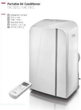
KOENIC
Ecoe-3B 120C 1230000000000000000000000000000
一
Sicherheitshinweise
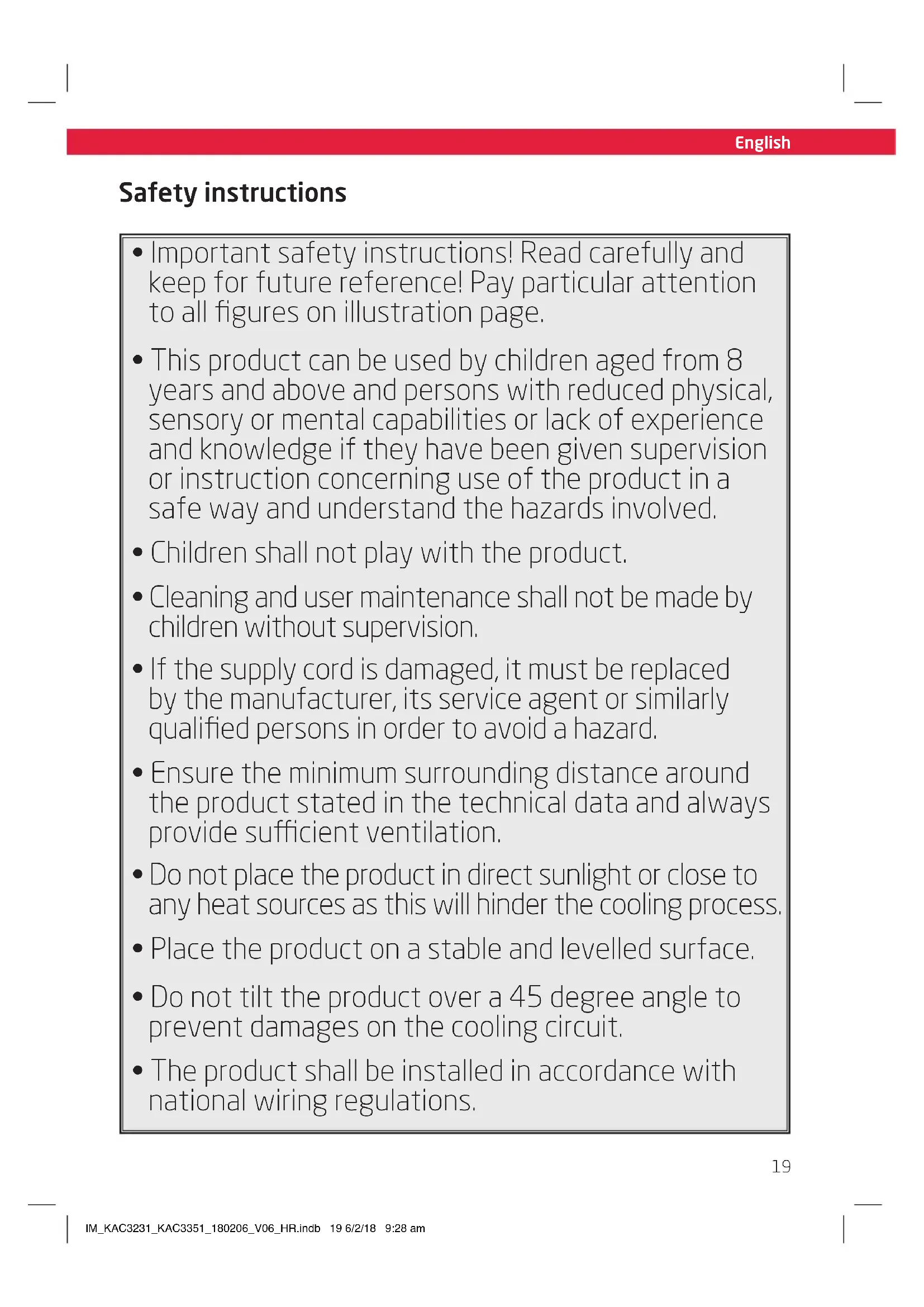
- Important safety instructions! Read carefully and keep for future reference! Pay particular attention to all figures on illustration page.
- This product can be used by children aged from 8 years and above and persons with reduced physical, sensory or mental capabilities or lack of experience and knowledge if they have been given supervision or instruction concerning use of the product in a safe way and understand the hazards involved.
- Children shall not play with the product.
- Cleaning and user maintenance shall not be made by children without supervision.
- If the supply cord is damaged, it must be replaced by the manufacturer, its service agent or similarly qualified persons in order to avoid a hazard.
- Ensure the minimum surrounding distance around the product stated in the technical data and always provide sufficient ventilation.
- Do not place the product in direct sunlight or close to any heat sources as this will hinder the cooling process.
- Place the product on a stable and levelled surface.
- Do not tilt the product over a 45 degree angle to prevent damages on the cooling circuit.
- The product shall be installed in accordance with national wiring regulations.
English
Safety instructions
-
Do not install the product in a location with high humidity or where splash water is likely to occur (e. g. laundry room).
-
Do not use the product in explosive atmospheres given through a combustible mixture of air and flammable fumes, vapours, mist or dust.
-
Do not use aerosol cans near the product.
-
The product is only for indoor use.
-
Position the product so that the plug is accessible.
-
Observe the minimal and maximal ambient temperature for operation stated in the technical data.
-
Do not attempt to modify the product in any way. Only use attachments and accessories recommended by the manufacturer.
-
Ensure the rated voltage shown on the rating label corresponds with the voltage of the power supply.
-
Do not operate any product with a damaged power cord or plug, when the product malfunctions or has been damaged in any manner.
-
Protect the power cord against damages. Do not let it hang over sharp edges, do not squeeze or bend them. Keep the power cord away from hot surfaces and ensure that nobody can trip over it.
Safety instructions
- Do not insert fingers or foreign objects in any opening of the product and do not obstruct the air vents.
- Protect the product against heat. Do not place close to heat sources such as stoves or heating products.
- Do not connect the product to extension cords or shared power outlets.
- WARNING! Switch the product off and disconnect it from the power supply before replacing attachments, cleaning work and when not in use.
- WARNING - RISK OF ELECTRIC SHOCK! Protect the electrical parts against moisture. Do not immerse such parts in water or other liquids to avoid electrical shock. Never hold the product under running water. Pay attention to the instructions for cleaning and care.
- Do not operate the product with wet hands or while standing on a wet floor. Do not touch the power plug with wet hands.
- This product is classified as protection class I and must be connected to a protective ground.
- Only use in dry indoor rooms.
English
Safety instructions
- Read this instruction manual carefully before using the product. Familiarise yourself with the operation, adjustments and functions of switches. Internalise and follow the safety and operation instructions in order to avoid possible risks and hazards.
- Keep batteries out of reach of children at all times.
- Seek immediate medical advice if batteries have been swallowed.
- Handle leaking batteries with proper protection and dispose them of accordingly. Prevent battery acid from coming into contact with skin and eyes. If you do get battery acid in your eyes or mouth, flush them thoroughly with lots of water and seek medical advice immediately. If battery acid comes into contact with your skin, wash the affected area with lots of water and soap.
Clean the contacts on batteries and the product prior to inserting. - Do not use old and new batteries, batteries of different types or different manufacturers together. Always replace all batteries of a set at the same time.
- Only use batteries recommended for this product; refer to technical data.
- Observe the polarity (+ and -) when inserting batteries. Pay attention to the markings on the product and the battery.
- Remove batteries from the product
if it is not to be used for an extended period of time.
- Remove exhausted batteries promptly from the product.
- Do not attempt charging nonrechargeable batteries.
- Never expose batteries to extreme environmental conditions like heat, cold or moisture.
- Do not dismantle, open or shred batteries.
- Do not short-circuit batteries. Do not store them haphazardly in a place where they may short-circuit each other or be short-circuited by other metal objects.
Use and assemble the product only as described with in this manual. - Examine the wall you want to install the air exhaust to before you start installation. Make sure that there are not hidden power supply cables, water or gas pipes or other objects hidden in the wall that might be hit by the drill.
- Keep children and pets away during installation. They might swallow up bits and pieces - danger of suffocation.
- Only use proper tools to install this product.
- Ensure to tighten screws well but do not over tighten them.
Congratulations!
Thanks for your purchase of KOENIC product. Please read this manual carefully and keep it for future reference.
Intended use
This air conditioner is designed to cool down or dehumidify indoor rooms.
The product is not intended for any commercial or industrial use. Do not use it for other purposes. Any other use might lead to damage of the product or personal injury.
The Imtron GmbH assumes no liability for damage to the product, for property damage or for personal injury due to careless or improper usage of the product, or usage of product which does not meet the manufacturer's specified purpose.
Before first time use
Remove the product and accessories carefully from the original packaging. It is recommended to keep the original packaging for storage. If you wish to dispose of the original packaging, please observe applicable legal provisions. Should you have any questions regarding proper disposal, contact your local waste management center. Inspect the delivery contents for completeness and damages. Should the delivery contents be incomplete or damaged, contact your sales outlet immediately.
After unpacking, please refer to chapter
Cleaning and care
Content
1 x Portable Air conditioner
1 x Remote Control
1 x Wall duct with cap
1 x Drainage hose
1 x Exhaust adapter
1 x Exhaust hose
1xWalladapter
4xWall plugs
4 x Screws
2 × Batteries (Type R03/AAA)
1 x User manual
Technical data
Power supply: 220 - 240 V~50 Hz
Maximum power input: 1160 W (KAC 3231)
:1600W(KAC3351)
Protection class : I
Fuse:T,250VAC,3.15AL
Cooling capacity : 2637 W (9000 BTU)
(KAC3231)
:3500W(12000BTU)
(KAC 3351)
Suitable for rooms up to max 80m^3 (KAC 3231)/max.120 m 3(KAC 3351)
Refrigerant: R410A / 0.330 kg
(KAC3231)
:R410A / 0.410 kg
(KAC3351)
Disposal

Do not dispose of this product as unsorted municipal waste. Return it to a designated collection point for the recycling of WEEE.
By doing so, you will help to conserve resources and protect the environment. Contact your retailer or local authorities for more information.
Refrigerants must be evacuated and disposed of by a qualified specialist in accordance with federal and local regulations before the appliance is scraped.

Please dispose of batteries in an environmentally friendly manner Do not put batteries into the household waste.
Please use the return and collection systems in your community or contact the dealer where you purchased the product.
English
Part list
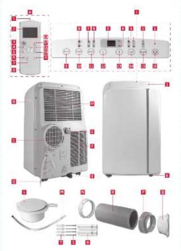
Remote control
- Remote control emitter
- Display with function indicators
- Power switch ON/OFF
- Mode selection button MODE
- Fan speed button FAN
- Sleep mode button SLEEP
- Oscillation button SWING
- Battery compartment with lid
- Display/indicator ON/OFF button LED
- Timer button TIMER OFF
- Timer button TIMER ON
- Pre-programmed button SHORT CUT
13.Temperature up/down/
B Recessed handle (on both sides)
Air exhaust
D Power cord and plug (not shown)
Lower drain outlet
Lower air filter
Upper drain outlet
H Upper air filter
Control panel
- Power indicator
- Sleep mode indicator
- Fan speed indicator
- Power management indicator
- Display
- Auto/Cool mode indicator
- Dehumidifying/Fan mode indicator
- Timer ON/OFF indicator
- Oscillation button SWING
- Timer program button TIMER
11.Mode selection button MODE
12.Temperature down/Decrease -
13.Temperature up/Increase + - Fan speed button FAN
15.Sleep mode button SLEEP
16.ON/OFF button
Fan opening
K Castors
Wall duct with cap
M Drainage hose
Exhaust adapter
0 Exhaust hose
P Wall adapter
Q Window outlet adapter
R Battery (RO3/AAA, 2x)
Screw (x4)
T Wall plug (x4)
Installation
Placement
When choosing an installation place, consider following points:
Observe all safety warnings!
- Ensure the minimum surrounding distance in every direction of 30~cm and 100~cm to other electrical products.
- Keep a surrounding distance of minimum 50~cm around the outside of exhaust wall outlet and protect it from entering objects and moisture.
Make sure the wall behind the product is an exterior wall not a divider and the drill holes can be made in a safe way, not obstructed by hidden objects in the wall.
- Ensure that a suitable power outlet is within reach at the desired location and remains accessible after installation.
- Consider that during dehumidifying operation water is collected inside the product, which must be continuously drained through a connected drainage hose into a suitable container or a nearby drain.
- Ensure there are no obstacles obstructing the airflow.
Air exhaust
The exhaust hose and adaptor must be installed or removed in accordance with the usage mode:
COOL, AUTO mode: install exhaust hose
FAN, DEHUMIDFY mode: remove exhaust hose
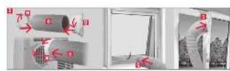
Wall mounting (Part:N,O,P)
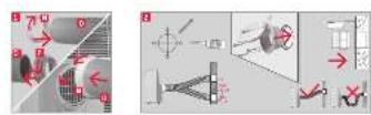
Fig.1 Screw the wall adapter and exhaust adapter onto each side of the exhaust hose. Connect the exhaust adapter to the air exhaust of the product.
Fig.2 Use the wall duct as pattern to mark the hole spacing on the wall. Drill the holes with a suitable power tool. Free the holes from dust and mount the wall duct using supplied screws and plugs. Connect the wall connector to the wall adaptor.
Window installation (Part: N, O, Q)
Fig.3 The exhaust hose can be attached to an open or tilted window alternatively. Screw the window outlet adapter onto the open end of the exhaust hose.
Note:
The exhaust hose can be expanded and compressed, but for optimal performance, keep the exhaust length to a minimum.
- Do not extend the exhaust hose.
- Avoid over-bending.
- Observe the decommissioning instructions in the respective section, if the product is not to be used for a longer period of time.
Material necessary for attachment and sealing is not provided but must be purchased in special shops
Drainage hose
The drainage hose is used to drain water from the upper drain outlet.
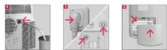
Fig. 4 Remove the rubber plug from the upper drainage outlet and slide the drainage hose as far as possible onto the outlet. Lead the other end of the drainage hose into a suitable container or a nearby drain.
Note:
Depending on the set modus the water is either drained directly or collected in an internal tank. Drain the water respectively.
- Attach the open end of the drainage hose to the drainage hose holder, when not in use.
Always cover the drain outlets when not in use.
- Observe the decommissioning instructions in the respective section, if the product is not to be used for a longer period of time.
English
Operation
Fig. 5 Switching on/off
The product can only be switched into Standby. Unplug in order to disconnect from the mains.
Press the on/off button or the ON/
OFF button to switch the product on or standby.
Note:
After a power break or when the product is switched into standby and on again in a short time, the refrigerating compressor will resume work after 3 minutes (delayed start). This is to prevent the cooling circuit from damages.
If the product is tilted over, switch it standby and unplug immediately. Wait at least 2 hours before operating the product again to avoid damages on the refrigerating circuit.
Always switch the product into standby before unplugging.
Remote control
Fig. 6 Remove the battery compartment cover. Insert 2 batteries (type R03/ AAA) while paying attention to the correct polarity. Close the battery compartment. Using the control panel and the remote control alternately might lead to a misalignment of the product and the information displayed on the remote control.
Note:
- Press any button on the remote control and the product adopts the current setting from the remote control.
The signals of the remote control will be transmitted with a short delay after a button is pressed. This process is indicated by the appearing symbol on the remote control display.
Every press of a button on the remote control will illuminate the display on the remote control for a few seconds for better visibility in the dark.
| Control panel | Remote control | Function |
| ON/OFF | Switch on or standby. | |
| + | TEMP | Increase value, e.g. temperature or timer |
| - | TEMP | Decrease value of temperature or timer |
| MODEMODE | Mode selection button | |
| FANFAN | Fan speed selection button | |
| SLEEP SLEEP | Sleep mode on/off | |
| SWING SWING | Fan outlet oscillation on/off | |
| - | LED | Display and indicator lights on/off |
| TIMER | TIME OFF | Adjust switch standby time |
| TIME ON | Adjust switch on time | |
| - | SHORT CUT | Choose preset mode and temperature |
Indicators
| Control panel | Remote control | Function |
| Timer On | Automatic on activated | |
| Timer Off | Automatic off activated | |
| Dry | Operating in de-humidifying mode | |
| Fan | Operating in fan mode | |
| auto | Auto | Operating in auto mode |
| Cool | Operating in cooling mode | |
| - | Heat | Function not provided |
| °C | °C | Unit indicator |
| - | Power manage-ment indicator * | |
| FAN | High fan speed | |
| FAN | Medium fan speed | |
| FAN | Low fan speed | |
| FAN auto | Fan speed set to Auto | |
| Sleep mode on/off | ||
| ● | Product on/standby | |
| - | Transmitting signal | |
* Power management indicator
-
When the ambient temperature is lower (Cooling mode) or higher (Heating mode) than the set temperature, the compressor and fan motor stops and the power management indicator illuminates.
-
When the ambient temperature is higher (Cooling mode) or lower (Heating mode) than the set temperature, the power management indicator turns off. The compressor and motor starts again.
Note:
- Every press of a button on the control panel and every successfully transmitted signal from the remote control is confirmed by an audible signal.
- All function of the product can be controlled via the control panel or the remote control, with exception of the display illumination LED and SHORTCUT buttons, which are to be found exclusively on the remote control.
Mode
| Mode Application | ||
| Auto | Automatic mode | ·products selects the suitable mode to achieve the set temperature ·fan speed is controlled automatically ·temperature can be adjusted |
| Cool | Cooling mode | ·cools down the room temperature ·the compressor runs and stops in order to maintain the set temperature ·fan speed and set temperature can be adjusted |
| Dry | Dehumidifying mode | ·dehumidifies the room with the fan ·fan speed and set temperature cannot be adjusted |
| Fan | Fan mode | ·fan only ·fan speed can be adjusted ·temperature cannot be adjusted |
English
| Timer On Timer Off | Timer mode | • switches the product on and / or into standby at a user-defined time |
| ● | Sleep mode | • set temperature increases by 1 °C after 30 minutes and again by 1 °C after another 30 minutes • temperature will be kept for the next 7 hours and the product returns then to the previously set temperature • not available during fan or dehumidifying mode |
The product is intended for the following ambient temperatures:
| Mode Temperature | |
| AUTO auto | 17 °C (62 °F) - 35 °C (95 °F) |
| COOL | 17 °C (62 °F) - 35 °C (95 °F) |
| DRY | 13 °C (55 °F) - 35 °C (95 °F) |

Warning
Any other conditions and locations as the mentioned above may result in reduced performance of the product, injuries and damage to property.
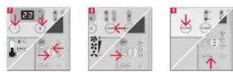
Fig.7 Setting the temperature
Press the + or button to select a temperature between 17^ to 30^
Fig.8 Setting the fan speed
- Press the fan speed button FAN to toggle between the speed settings.
The respective indicator on the control panel and the remote control show the current setting.
Note:
There is no indicator for the auto speed setting.
Fig. 9 Air outlet adjustment
The air outlet can be adjusted in any mode to fit required needs.
- Press the oscillation button SWING repetitively to turn oscillation on or off. The air flap will oscillate continuously.
- To stop the air flap at a desired position press button SWING again.
Note:
Do not move, open or shut the air flap manually.
Fig.10 Setting the timer
The timer switches the product on or standby when a user-defined time has elapsed. When switching on, the last mode and setting will be used.
The set durations will be counted down immediately.
- Press the timer program button TIMER at the product or the specific TIME ON/OFF button at the remote control to enter timer setting for either the auto-on or auto-off timer. The respective indicator for each setting will light up.
- Press the + / - buttons or the specific TIME ON/OFF button at the remote control as often as necessary to set a time from 0.5 to 24 hours.
The setting will be saved in the product after 5 seconds without input.
Note:
The indicator lights are on when the timer is activated.
Examples:
- To have the product switched standby after 1 hour and on again after another 112 hours, set the auto-off time to 1.0 h and the auto-on time to 2.5 h during operation.
- To have the product switched on after 8 hours and standby after another 8 hours, set the auto-on time to 8.0h and the auto-off time to 16.0h while in standby.
Note:
The adjusting increments are 0.5 hours up to 10 hours, then 1 hour up to 24 hours.
The respective indicator will be lit, when a time is set.
- Switching the product on or into standby manually will cancel the timer setting.
- The timer settings will be lost once the respective actions were conducted and the time needs to be set again. The timer setting will be lost in case an error occurs (see protection and error codes).
Preprogramming a function
By pushing the SHORTcut button any function and temperature can be saved and recalled.
- Choose your desired function e.g. using the MODE, TEMP / + or - and FAN buttons, etc.
- Press and hold SHORTCUT button until the display flashes one time to save the setting.
- The preset setting can be recalled anytime and from any mode by simply pushing the SHORTCUT button.
Fig.11 Water drainage
Water is only collected during automatic AUTO, cooling COOL and dehumidifying mode DRY.
During dehumidifying mode DRY water is drained immediately through the upper drain outlet and the drainage hose must be continuously connected.
The water must be drained through the hose into a suitable container or nearby drain using the upper drain outlet.
Note:
KAC3231 is equipped with a self-evaporating system. The condensing water is self-evaporated and released through the air exhaust.

Warning
Danger of flooding! Do not leave the product unattended when draining to an external container! Empty the container frequently to avoid spilling over and water damage.
Note:
If the water is not drained to an external container and the upper drain outlet is closed during automatic AUTO or cooling mode
COOL water is collected in an internal tank, which must be drained when full. In this case the product will emit an audible signal, while the display on the control panel is showing the protection code P1. The cooling process will stop until the water is drained and the product restarted, while the fan remains running.
- Disconnect the product from the power supply.
- Place the product with the lower drain outlet above a suitable container or a drain.
- Remove the cover of the lower drain outlet.
- Attach the cover of the outlet again, when all water is drained.
- Connect the plug to a suitable socket.
The product is ready to be switched on.
Under some circumstances (e.g. high humidity) the self-evaporation system may not be sufficient to handle the water and excessive water is collected in the internal tank, which must be drained as described above when full.
English
Cleaning & care
Fig.12 Switch the product into Standby and unplug in order to disconnect from the mains.
Note:
Clean the product every two weeks. Clean the outer surfaces of the product with a damp cloth soaked in neutral detergent. Dry it with a lint-free cloth. Do not use chemical, alkaline, abrasive or other aggressive detergents as they might be harmful to the surfaces.
Fig.13 Remove the air filters. Clean the air filters in warm water (below 40^ ) and neutral detergent.
Fig.14 Let them dry thoroughly before re-attaching.
- Do not open the housing of the product and do not insert any tools into the air vents.
- This product does not contain any parts that can be repaired or serviced by the consumer. Contact a qualified specialist to have it checked and repaired as necessary.
Decommissioning
Fig.15 Drain all water from the product and dry it using the fan mode FAN for half a day in a dry, warm room to prevent mould. Switch the product into standby. Unplug and wind the power cord around the cord storage. Remove the exhaust hose assembly from the product and wall duct. Close the wall duct with the cap. Cover all drain outlets. Remove the batteries from the remote control. Close the cover of the wall adaptor.
Transportation
Fig.16 Wait at least 2 hours after moving before operating the product to avoid damages on the refrigerating circuit.
Note:
The product is heavy. Therefore move the product whenever possible by pushing or pulling it, rolling on the castors. When lifting is unavoidable, use the recessed handles and lift with two people. Do not move the product during operation.
Troubleshooting
If there are any problems during operation, please refer to the following table. If problems cannot be solved as indicated under Solution, please contact your manufacturer.

Warning
Only perform the steps described within this instruction manual. All further inspection, maintenance and repair work must be performed by an authorised service centre or a similarly qualified specialist.
| Problem Possible cause | Solution | |
| product does not start not | connected to power supply connect to power supply | |
| power cord or plug is defective check by a specialist | ||
| other electrical defect to the product | check by a specialist | |
| error occurred see protection and error codes | ||
| remote control faulty see below | ||
| remote control not working | batteries exhausted replace batteries | |
| product out of range or signals disrupted by obstacle | move the remote control closer and clear obstructions | |
| other electrical defect to the remote control | check by a specialist | |
| timer not working implausible, contradictory or wrong time set | check timer setting | |
| unsatisfactory cooling near | arby heat source hinders cooling process | relocate product or remove heat source |
| ventilation insufficient ensure surrounding clearance | ||
| open window(s) or door(s) in the room | close window(s) / door(s) | |
| exhaust hose not properly connected or blocked | connect properly or check for and remove blockage | |
| air filter(s) blocked clean air filter(s) | ||
| temperature set too high regulate the temperature controller | ||
| noise product is not levelled level the product | ||
| product contacts obstacle | remove obstacle | |
English
Note:
Murmur of water is heard when the product is operating. It is a normal sound of the coolant circulating in the system.
Protection and error codes
| Code | Cause Solution | |
| P1 | internal water tank full | drain through lower outlet |
| E1 | room temperature sensor error | switch the product into standby, unplug and re Plug |
| E2 | evaporator temperature sensor error | switch the product into standby, unplug and re Plug |
| E4 | control panel communication error | switch the product into standby, unplug and re Plug |
Note:
Contact the service centre if errors occur.
reputably.
Information requirements
Product fiche
Local air conditioners
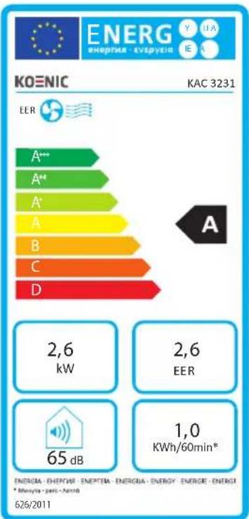
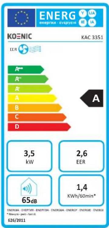
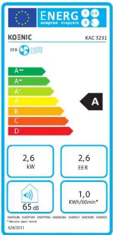
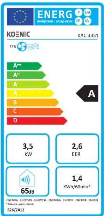
| KOENIC | KAC 3231 | KAC 3351 | ||
| Description Symbol Value Unit | ||||
| Sound power level | LWA | 65.6 | 5 dB | |
| Global warming potential * | GWP | 2088 | 2088 | kg CO2 eq. |
| Rated capacity for cooling | Prated | 2.6 | 3.5 kW | |
| Rated capacity for heating | Prated | n/a n | a kW | |
| Rated power input for cooling | PEER | 1.0 | 1.4 kW | |
| Rated power input for heating | PCOP | n/a n | a kW | |
| Rated Energy efficiency ratio | EERd | 2.6 | 2.6 - | |
| Rated Coefficient of performance | COPd | n/a n | a - | |
| Power consumption in thermostat-off mode | PTO | 0.9 | 1.0 W | |
| Power consumption in standby mode | PSB | 0.5 | 0.5 W | |
| Electricity consumption of single/double duct products (indicate for cooling and heating separately) | DD: QDD SD: QSD | n/a 1.0 | n/a 1.4 | DD: kWh/a SD: kWh/h |
| Contact details for obtaining more information | Imtron GmbH Wankelstraße 5, 85046 Ingolstadt Germany | |||
The rated cooling capacity was tested under following conditions:
| Cooling operation | Indoor | 35 °C (DB) 24 | °C (WB) |

Note:
- This product contains fluorinated greenhouse gas (hermetically sealed) which is dangerous for the environment and contributes to global warming if released to the atmosphere.
Refrigerant type: R410A
Global warming potential (GWP): 2088 - Refrigerant leakage contributes to climate change. Refrigerant with lower global warming potential (GWP) would contribute less to global warming than a refrigerant with higher GWP, if leaked to the atmosphere.
- This product contains a refrigerant fluid with a GWP equal to 2088. This means that if 1kg of this refrigerant fluid would be leaked to the atmosphere, the impact on global warming would be 2088 times higher than 1kg of CO_2 , over a period of 100 years. Never try to interfere with the refrigerant circuit yourself or disassemble the product yourself and always ask a professional.
- Energy consumption 1.0 kWh (KAC 3231)/ 1.4 kWh (KAC 3351) per 60 minutes, based on standard test results. Actual energy consumption will depend on how the product is used and where it is located.
Wiring diagram
See annex.
Français
Fig.11 Evacuation de I'eau
Informations requires
Fiche produit
Zekering:T,250VAC,3.15AL
Draagbare airconditioners