
KAC 14022 - Air Conditioning Koenic - Free user manual and instructions
Find the device manual for free KAC 14022 Koenic in PDF.


| Product Type | Monobloc Portable Air Conditioner |
| Brand | Koenic |
| Model | KAC 14022 WLAN |
| Cooling Capacity | 14000 BTU/h (4.1 kW) |
| Power Supply | 220-240 V~ 50 Hz |
| Rated Power Input | 1650 W |
| Rated Current | 8.5 A |
| Protection Class | I |
| Refrigerant | R290 (270 g) |
| Sound Power Level | 65 dB(A) |
| Energy Efficiency Ratio (EER) | 2.6 |
| Operating Modes | Cool, Fan, Dry, Smart |
| Fan Speeds | Auto, Low, Med, High |
| Programmable Timer | Yes (1-24h on unit, 0.5-24h on remote) |
| Special Functions | Turbo, Sleep, Swing, Child Lock, WiFi |
| Remote Control | Yes (with R03/AAA batteries) |
| Air Filter | Washable (2 filters) |
| Air Exhaust | Exhaust hose included (wall or window mounting) |
| Drainage | Internal tank + drain hose |
| Auto-Evaporation System | Yes |
| Castors | Yes for mobility |
| Included Accessories | Remote control, wall sleeve, drain hose, exhaust adapter, wall adapter, window adapter, wall plugs, screws, batteries |
Frequently Asked Questions - KAC 14022 Koenic
User questions about KAC 14022 Koenic
0 question about this device. Answer the ones you know or ask your own.
Ask a new question about this device
Download the instructions for your Air Conditioning in PDF format for free! Find your manual KAC 14022 - Koenic and take your electronic device back in hand. On this page are published all the documents necessary for the use of your device. KAC 14022 by Koenic.
USER MANUAL KAC 14022 Koenic
[Non-Text]
[Non-Text]
[Non-Text]
[Non-Text]
[Non-Text]
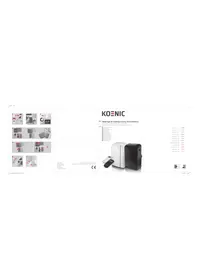
natural_image
White portable air purifier with front panel and control panel (no visible text or symbols)| Cancer 3-37 | — |
| Engel 38-10 | — |
| Spinal 5-10 | — |
| Tumor 11-15 | — |
| EOPar 116-143 | — |
| Vagia 124-164 | — |
| Lum 170-195 | — |
| Eosm 197-225 | — |
| PheA 224-250 | — |
| Pegal 250-270 | — |
| Stenck 270-309 | — |
| Tumor 300-330 | — |
Sicherheitshinweise
Caution: Risk of fire/ flammable materials.
This symbol indicates that ignoring instructions may cause death or serious injury.

WARNING: To prevent death or injury to the user or other people and property damage, the following instructions must be followed. Incorrect operation due to ignoring of instructions may cause death, harm or damage.
IMPORTANT NOTE: Read this manual carefully before installing or operating your new air conditioning unit. Make sure to save this manual for future reference.

Appliance KAC 12022 WLAN/ KAC 12022 CH WLAN should be installed, operated and stored in a room with a floor area larger than 13 m ^2 . Appliance KAC 14022 WLAN/ KAC 14022 CH WLAN should be installed, operated and stored in a room with a floor area larger than 13m^2 .
• Installation must be performed according to the installation instructions. Improper installation can cause water leakage, electrical shock, or fire.
- Use only the included accessories and parts, and specified tools for the installation. Using non-standard parts can cause water leakage, electrical shock, fire, and injury or property damage.
English
Safety instructions
- Make sure that the power outlet you are using is grounded and has the appropriate voltage. The power cord is equipped with a three-prong grounding plug to protect against shock. Voltage information can be found on the nameplate of the unit.
- Your unit must be used in a properly grounded wall receptacle. If the wall receptacle you intend to use is not adequately grounded or protected by a time delay fuse or circuit breaker (the fuse or circuit breaker needed is determined by the maximum current of the unit. The maximum current is indicated on the nameplate located on the unit), have a qualified electrician install the proper receptacle.
- Install the unit on a flat, sturdy surface. Failure to do so could result in damage or excessive noise and vibration.
- The unit must be kept free from obstruction to ensure proper function and to mitigate safety hazards.
- DO NOT modify the length of the power cord or use an extension cord to power the unit.
- DO NOT share a single outlet with other electrical appliances to avoid overloads. Improper power supply can cause fire or electrical shock.
- DO NOT install your air conditioner in a wet room such as a bathroom or laundry room. Too much exposure to water can cause electrical components to short circuit.
Safety instructions
- DO NOT install the unit in a location that may be exposed to combustible gas, as this could cause fire.
- The unit has wheels to facilitate moving. Make sure not to use the wheels on thick carpet or to roll over objects, as this could cause the product to tip over.
- DO NOT operate a unit that it has been dropped or damaged.
- Appliances with an electric heater shall have at least 1 meter space to the combustible materials.
- Do not touch the unit with wet or damp hands or when standing barefoot on a wet floor.
- If the air conditioner is knocked over during use, turn off the unit and unplug it from the main power supply immediately. Visually inspect the unit to ensure there is no damage. If you suspect the unit has been damaged, contact a technician or customer service for assistance.
- In a thunderstorm, the power must be cut off to avoid damage to the machine due to lightning.
- Your air conditioner should be used in such a way that it is protected from moisture e.g. condensation, splashed water, etc. Do not place or store your air conditioner where it can fall or be pulled into water or any other liquid. Unplug immediately if it occurs.
- All wiring must be performed strictly in accordance with the wiring diagram located inside of the unit.
English
Safety instructions
- The unit's circuit board(PCB) is designed with a fuse to provide overcurrent protection. The specifications of the fuse are printed on the circuit board.
- This appliance can be used by children aged from 8 years and above and person with reduced physical, sensory or mental capabilities or lack of experience and knowledge if they are being supervised, or have received instruction concerning use of the appliance in a safe way and understand the hazards involved. Children shall not play with the appliance. Cleaning and user maintenance shall not be carried out by children without supervision.
- Children should be supervised to ensure that they do not play with the appliance. Children must be supervised around the unit at all times.
- If the supply cord is damaged, it must be replaced by the manufacturer, its service agent or similarly qualified persons in order to avoid a hazard.
- Prior to cleaning or other maintenance, the appliance must be disconnected from the supply mains.
- Do not remove any fixed covers. Never use this appliance if it is not working properly, or if it has been dropped or damaged.
- Do not run the power supply cord under carpeting. Do not cover it with throw rugs, runners, or similar coverings. Do not route it under furniture or appliances. Keep it from areas that are frequently entered and make sure it will not be tripped over.
Safety instructions
- Do not operate the unit with a damaged cord, plug, power fuse or circuit breaker. Discard the unit or return it to an authorized service facility for examination and/or repair.
- To reduce the risk of fire or electric shock, do not use the device with any solid-state speed control device.
- The appliance shall be installed in accordance with national wiring regulations.
- Contact the authorized service technician for repair or maintenance of this unit.
- Do not cover or obstruct the inlet or outlet grilles.
- Do not use this product for functions other than those described in this instruction manual.
- Before cleaning, turn off the power and unplug the unit.
- Disconnect the power if strange sounds, smell, or smoke occurs.
- Do not press the buttons on the control panel with anything other than your fingers.
- Do not remove any fixed covers. Never use this appliance if it is not working properly, or if it has been dropped or damaged.
English
Safety instructions
- Do not operate or stop the unit by inserting or pulling out the power cord plug.
- Do not use hazardous chemicals for cleaning or let them come into contact with the unit. Do not use the unit in the presence of inflammable substances or vapour such as alcohol, insecticides, petrol, etc.
• Always transport your air conditioner in a vertical position and place it on a stable, level surface during use. - Always contact a qualified person to carry out repairs. If the power supply cord is damaged, it must be replaced with a new power supply cord, which must be obtained from the product manufacturer and the damaged one must not be repaired.
- Only unplug from the power socket by the plug itself. Do not pull on the cord.
- Turn off the product when not in use.
- Keep batteries out of reach of children at all times.
- Seek immediate medical advice if batteries have been swallowed.
- Handle leaking batteries with proper protection and dispose of them accordingly. Prevent battery acid from coming into contact with skin and eyes. If you do get battery acid in your eyes or mouth, flush them thoroughly with lots of water and seek medical advice immediately. If battery acid comes into contact with your skin, wash the affected area with lots of water and soap.
Safety instructions
- Clean the contacts on batteries and the product prior to inserting.
- Do not use old and new batteries, batteries of different types or different manufacturers together. Always replace all batteries of a set at the same time.
- Only use batteries recommended for this product; refer to technical data.
- Observe the polarity (+ and -) when inserting batteries. Pay attention to the markings on the product and the battery.
- Remove batteries from the product if it is not to be used for an extended period of time.
- Remove exhausted batteries promptly from the product.
- Do not attempt to charge non-rechargeable batteries.
- Never expose batteries to extreme environmental conditions like heat, cold or moisture.
- Do not dismantle, open or shred batteries.
- Do not short-circuit batteries. Do not store them haphazardly in a place where they may short-circuit each other or be short-circuited by other metal objects.
English
Safety instructions
Warnings (concerning the R290 refrigerant)
- Do not use means to accelerate the defrosting process or for cleaning, other than those recommended by the manufacturer.
- The appliance shall be stored in a room without continuously operating ignition sources (for example: open flames, an operating gas appliance or an operating electric heater).
- Do not pierce or burn the appliance.
- Compliance with national gas regulations shall be observed.
- Keep ventilation openings clear of obstruction.
- The appliance shall be stored so as to prevent mechanical damage from occurring.
- The appliance shall be stored in a well-ventilated area where the room size corresponds to the room area as specified for operation.
- Any person who is involved with working on or breaking into a refrigerant circuit must hold a current valid certificate from an industry-accredited assessment authority, which authorises their competence to handle refrigerants safely in accordance with an industry recognised assessment specification.
Safety instructions
- Servicing shall only be performed as recommended by the equipment manufacturer. Maintenance and repair requiring the assistance of other skilled personnel shall be carried out under the supervision of the person competent in the use of flammable refrigerants.
- Transport of equipment containing flammable refrigerants. See transport regulations
- Marking of equipment using signs. See local regulations
- Disposal of equipment using flammable refrigerants. See national regulations.
- Storage of equipment/appliances.
The storage of equipment must be in accordance with the manufacturer's instructions.
• Cabling
Check that cabling will not be subject to wear, corrosion, excessive pressure, vibration, sharp edges or any other adverse environmental effects. The check shall also take into account the effects of aging or continual vibration from sources such as compressors or fans.
English
Safety instructions
• Detection of flammable refrigerants
Under no circumstances shall potential sources of ignition be used in the searching for or detection of refrigerant leaks. A halide torch (or any other detector using a naked flame) shall not be used.
Note about non fluorinated gases
- Non fluorinated greenhouse gases are contained in hermetically sealed equipment. For specific information on the type, the amount and the CO_2 equivalent in tonnes of the non fluorinated greenhouse gas (on some models), please refer to the relevant label on the unit itself.
- Installation, service, maintenance and repair of this unit must be performed by a certified technician.
- Product uninstallation and recycling must be performed by a certified technician.
Safety instructions
- Read this user guide carefully before first use. It contains important safety information as well as instructions for the use and care of the device. Save the guide for later reference and include it with the device when transferring it to a third party.
- To avoid dangerous situations, do not use the product for any purpose other than those described in the instructions. Improper use is dangerous and voids the warranty.
-
Read this instruction manual carefully before using the product. Familiarise yourself with the operation, adjustments and functions of the controls. Internalise and follow the safety and operation instructions in order to avoid possible risks and hazards.
-
Use and assemble the product only as described with in this manual.
- Examine the wall you want to install the air exhaust to before you start the installation. Make sure that there are no hidden power supply cables, water or gas pipes or other objects hidden in the wall that might be hit by the drill.
- Keep children and pets away during installation. They might swallow up bits and pieces – danger of suffocation.
- Only use proper tools to install this product.
- Ensure to tighten screws well but do not over tighten them.
Explanation of symbols displayed on the unit
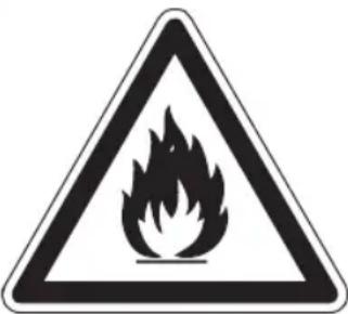 | WARNINGThis symbol shows that this product used a flammable refrigerant. If the refrigerant is leaking and exposed to an external ignition source, there is a risk of fire. | |
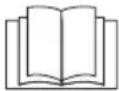 | CAUTION This symbol shows that the instruction manual should be read carefully. | |
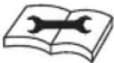 | CAUTION This symbol shows that a service personnel should be handling this equipment with reference to the installation manual. | |
 | CAUTION This symbol shows that information is available such as the instruction manual or installation manual. | |
Congratulations!
Thank you for your purchase of a KOENIC product. Please read this manual carefully and keep it for future reference.
Intended use
This air conditioner is designed to cool down or dehumidify indoor rooms.
The product is not intended for any commercial or industrial use. Do not use it for other purposes. Any other use might lead to damage of the product or personal injury. Imtron GmbH assumes no liability for damage to the product, for property damage or for personal injury due to careless or improper usage of the product, or usage of product which does not meet the manufacturer's specified purpose.
Before first time use
Remove the product and accessories carefully from the original packaging. It is recommended to keep the original packaging for storage. If you wish to dispose of the original packaging, please observe applicable legal provisions. Should you have any questions regarding proper disposal, contact your local waste management center. Inspect the delivery contents for completeness and damages. Should the delivery contents be incomplete or damaged, contact your sales outlet immediately.
After unpacking, please refer to chapter
Cleaning and care.
Disposal
The symbol of the crossed-out wheeled bin shown on the product or its packaging means that the device must not be disposed of with other household waste but requires separate collection. You can dispose of the device free of charge at your local waste return and collection system. The addresses can be obtained from your responsible city council or local government. Alternatively, you can return small waste electrical and electronic equipment (WEEE) with an edge length of up to 25 cm free of charge to any retailer with a sales area relating to electrical and electronic equipment (EEE) of at least 400 m² or to a food retailer that offers EEE at least several times a year with a total sales area of 800 m². Larger WEEE can be returned to a respective retailer free of charge when buying a new product of the same type. Regarding the modalities of the collection of WEEE in case of shipment of the newly bought product, please contact your retailer. If possible, please remove all batteries and accumulators as well as all removable lamps before disposing of the device. Please note that you are responsible for deleting all personal data on the device to be disposed of.
Refrigerants must be evacuated and disposed of by a qualified specialist in accordance with federal and local regulations before the appliance is scraped.

The symbol of the crossed-out wheeled bin shown on the battery or its packaging means that the battery must not be disposed of as unsorted municipal waste. In case the batteries contain more than 0,0005 % mercury (Hg), more than 0,002 % cadmium (Cd) or more than 0,004 % lead (Pb), the respective chemical symbol will be shown below the symbol of the crossed out wheeled bin. You can return waste batteries free of charge at your local waste return and collection system, whose addresses can be obtained from your responsible city council or local government, as well as in retail stores.
Returned waste batteries can be prepared for recycling in order to reduce waste and save resources. Please note that you are legally obliged to return batteries.
Batteries may contain substances which are harmful for the environment and human health. Due to the particular risks involved with lithium, special care must be taken when handling batteries containing it. The separate collection and recycling of waste batteries helps to prevent negative consequences for the environment and human health.
To avoid the generation of waste, please prefer batteries with a longer life or rechargeable batteries. To avoid littering, please do not leave batteries in public space but collect and return them for recycling.
Delivery Content
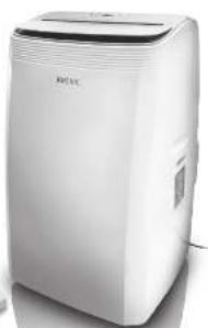
1 x Portable Air conditioner
1 x Remote Control
1 x Wall duct with cap
1 x Drainage hose
1 x Exhaust adapter
1 x Exhaust hose
1 x Flat adapter
1 x Wall adapter
4 x Wall plugs
4 x Screws
2 x Batteries (Type R03/AAA)
1 x User manual
1 x Warranty Card
Technical data
KAC 12022 WLAN
Power supply : 220 - 240 V\~ 50 Hz
Rated input power : 1450 W/7.0 A
Protection class : I
Fuse : 250 V T3.15A
Cooling capacity : 12000 BTU/h
Refrigerant : R290/ 260 g
Frequency range : 2412 - 2472 MHz
Max RF power : 20 dbm
KAC 14022 WLAN
Power supply : 220 - 240 V\~ 50 Hz
Rated input power : 1650 W/8.5 A
Protection class : I
Fuse : 250 V T3.15A
Cooling capacity : 14000 BTU/h
Refrigerant : R290/ 270 g
Frequency range : 2412 - 2472 MHz
Max RF power : 20 dbm
English
Declaration of conformity
Hereby, Imtron GmbH declares that the radio equipment type KAC 12022 WLAN/KAC 12022 CH WLAN/KAC 14022 WLAN/KAC 14022 CH WLAN is in compliance with Directive 2014/53/EU. The full text of the EU declaration of conformity is available at the following internet address: http://www.koenic-online.com/nc/suche.html
Impedance Information:
To be in compliance EN 61000-3-11, the product KAC 12022 WLAN/ KAC 12022 CH WLAN/ KAC 14022 WLAN/ KAC 14022 CH WLAN shall be connected only to a supply of the system impedance: | Zsys|=0.362 ohms or less. Before connecting the product to a public power network, please consult your local power supply authority to ensure the power network meets above requirement.
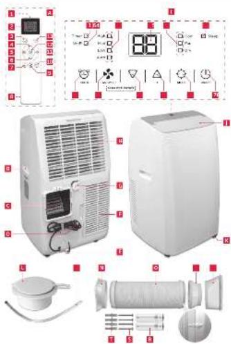
Controls and components
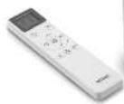
A Remote control
- Remote control transmitter
- Display
- On/off button
- ^button
- Timer button
- √ button
- Night mode button
- Battery compartment with cover
- Fan speed button
- Temperature unit button °C / °F
- Air outlet oscillation button
- Mode selection button
- Function button
B Recessed handle (on both sides)
c Air exhaust
D Power cord and plug
Lower drain outlet
F Lower air filter
G Upper drain outlet
H Upper air filter
Control panel
- Indicator Timer
- Indicator Wifi
- Fan speed indicator
- Display
- Mode indicator Dry/Fan/Cool
- Indicator Sleep
- ON/OFF button
- MODE button
-
- button
10.-button
- button
- FAN SPEED button
- TIMER button
Auto/Low/Med/High
J Fan opening
K Castors
L Wall duct with cap
M Drainage hose
N Exhaust adapter
0 Exhaust hose
P Wall adapter
Flat adapter
R Battery (RO3/AAA, 2x)
S Screw (x4)
T Wall plug (x4)
Installation
Placement
When choosing an installation place, consider the following points:
- Observe all safety warnings!
- Ensure the minimum surrounding distance in every direction of 45 cm and 100 cm to other electrical products.
- Keep a surrounding distance of minimum 50 cm around the outside of the exhaust wall outlet and protect it from entering objects and moisture.
• Make sure the wall behind the product is an exterior wall not a divider and the drill holes can be made in a safe way, and are not obstructed by hidden objects in the wall. - Ensure that a suitable power outlet is within reach at the desired location and remains accessible after installation.
- Consider that during dehumidifying mode water is collected inside the product, which must be continuously drained through a connected drainage hose into a suitable container or a nearby drain.
- Ensure, that there are no obstacles obstructing the airflow.
Note:
If the product has been transported in a horizontal position, it must not be plugged in for 24 hours, in order to avoid damages of the cooling system.
Air exhaust
The exhaust hose and adaptor must be installed or removed in accordance with the usage mode:
• COOL mode: install exhaust hose
• FAN mode: no need to install exhaust hose
- DEHUMIDFY mode: install exhaust hose
Wall mounting (Part: N, O, P)
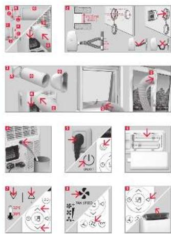
Fig. 1 Connect the wall adapter and exhaust adapter with each side of the exhaust hose. Connect the exhaust adapter to the air exhaust of the product.
Fig. 2 Use the wall duct as pattern to mark the hole spacing on the wall. Drill the holes with a suitable power tool. Free the holes from dust and mount the wall duct using the supplied screws and plugs. Connect the wall connector to the wall adaptor.
Note:
- The exhaust hose can be expanded and compressed, but for optimal performance, keep the exhaust length to a minimum.
- Do not extend the exhaust hose.
- Avoid over-bending.
- Observe the decommissioning instructions in the respective section, if the product is not to be used for a longer period of time.
Window installation (Part: N, O, Q)
Fig. 3 The exhaust hose can be attached to an open or tilted window alternatively. Attach the window outlet adapter to the open end of the exhaust hose.
Recommendation:
- For faster and better distribution of the cold air, we recommend to use an additional fan.
- If the exhaust air hose is routed to the outside through a tilted window or door, we recommend to seal the gap. For this purpose, sealing sets are available in our stores.
Drainage hose
The drainage hose is used to drain water from the upper drain outlet.
Fig. 4 Remove the rubber plug from the upper drainage outlet and slide the drainage hose as far as possible onto the outlet. Lead the other end of the drainage hose into a suitable container or a nearby drain.
Note:
- Depending on the set modus the water is either drained directly or collected in an internal tank. Drain the water respectively.
- Attach the open end of the drainage hose to the drainage hose holder, when not in use.
English
• Always cover the drain outlets when not in use.
- Observe the decommissioning instructions in the respective section, if the product is not to be used for a longer period of time.
Operation
Fig. 5 Switching on/off
The product can only be switched on or into Standby. Unplug in order to disconnect from the mains. Press the on/off button or the ① button to switch the product on or into standby.
Note:
• After a power break or when the product is switched into standby and on again in a short time, the refrigerating compressor will resume work after 3 minutes (delayed start). This is to prevent the cooling circuit from damages.
- If the product is tipped over, switch it into standby and unplug immediately. Wait at least 2 hours before operating the product again to avoid damages on the refrigerating circuit.
• Always switch the product into standby before unplugging.
Remote control
Fig. 6 Remove the battery compartment cover. Insert 2 batteries (type R03/AAA) while paying attention to the correct polarity. Close the battery compartment. Using the control panel and the remote control alternately might lead to a misalignment of the product and the information displayed on the remote control.
Note:
- Press any button on the remote control and the product adopts the current setting from the remote control.
- The signals of the remote control will be transmitted with a short delay after a button is pressed.
Buttons
| Control panel | Remote control | Function |
 |  | Switch on or into standby |
 |  | Increase value of temperature or timer |
 |  | Decrease value of temperature or timer |
 |  | Mode selection button |
 |  | Fan speed selection button |
 | Sleep (Comfort) mode on/off | |
 | Fan outlet oscillation on/off | |
 |  | Set the temperature unit |
 |  | Set the timer |
 | Function |
Note:
The device is equipped with a self-evaporating system. The condensing water is self-evaporated and released through the air exhaust. Please note that depending on the set mode, water will be collected in the internal tank or drained through the hose.
Indicators
| Control panel | Remote control | Function |
 | Operating in de-humidifying mode | |
| Operating in fan mode | ||
 |  | Operating in cooling mode |
 | [7XK] | Low fan speed |
 | [3XKAC] | Medium fan speed |
 | High fan speed | |
 | Auto speed | |
| — | [4V8A] | Air outlet oscillation |
| — |  | Comfort mode on/o |
 | Product on/standby | |
 | Smart mode | |
| — | Signal | |
 | Unit indicator (°C/F) | |
| Child lock | ||
| Timer on | ||
| Timer o | ||
| — | Turbo |
Note:
- Every press of a button on the control panel and every successfully transmitted signal from the remote control is confirmed by an audible signal.
- All functions of the product can be controlled via the control panel or the remote control, with exception of the Sleep and Swing function button to be found exclusively on the remote control.
English
Mode
Press the Mode button to choose one of the modes:
| Mode | Description Button | Display | |||
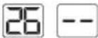
| Cool | • cools down the room temperature• the compressor runs and stops in intervals in order to maintain the set temperature• fan speed and set temperature can be adjusted | Product | Temperature18°C-32°C(64°F-90°F) | △▽ | 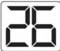 |
| Fan speed(High / Medium/ Low / Auto) | [S3K2] | ||||
Remote control | Temperature18°C-32°C(64°F-90°F) |  | 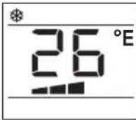 | ||
| Fan speed(High / Medium/ Low / Auto) |  | Low Medium High Auto [High] [Low] [Low] [Low] [Low] | |||
| Fan | • fan only• fan speed can be adjusted• temperature cannot be adjusted | Product[S44H] | Fan speed(High / Medium/ Low) | [S8XW] | 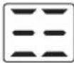 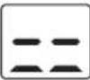 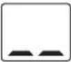 |
Remote control | Fan speed(High / Medium/ Low) |  |  | ||
| Dry | • dehumidifies the room with the fan• fan speed and set temperature cannot be adjusted | Product | — | — | 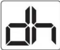 |
Remote control | — | — |  | ||
| Smart | • automatically operates in cool or fan mode.• the product operates in Fan mode when the room temperature is below 23°C (73°F), and Cool mode when the room temperature is above 23°C(73°F). | Product | Fan speed(High / Medium / Low / Auto): |  | 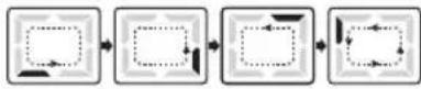 |
Remote control | Fan speed(High / Medium / Low / Auto): |  | 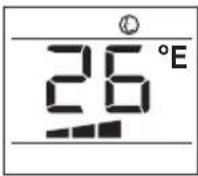 | ||
| Timer | • switches the product on or into standby at a user-defined time | Product | Hours (1-24) | — | |
| Remote controlL | Hours(0.5-24) |  | 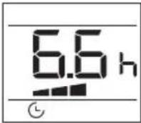 | ||
| Comfort | • The set temperature increases by 1 °C after 1 hour and again by 1 °C after another 1 hour and the display will be less illuminated.• Not available during fan or dehumidifying mode. |  | — | — | 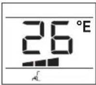 |
| Function | TurboCan be activated in the mode cooling/ dry/fan/smart |  | — | — | 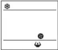 |
| Child lock | • Protects against accidental alterations | — | — | Press and hold 3 seconds | 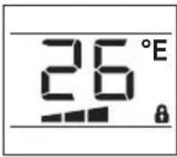 |
English
The product is intended for the following ambient temperatures:
| Mode Temperature | |
| COOL 18 | °C (64 °F) - 35 °C (95 °F) |
| DRY 18 | °C (64 °F) - 35 °C (95 °F) |

Warning
Any other conditions and locations as the ones mentioned above may result in reduced performance of the product, injuries and damage to property.
Fig. 7 Setting the temperature
Press the ↗+ or ↗-button to select a temperature between 18 °C to 32 °C.
- Press the fan speed button ✿ to toggle between the speed settings.
- The respective indicator on the control panel and the remote control show the current setting.
Fig. 9 Air outlet adjustment
The air outlet can be adjusted in any mode to fit the required needs.
- Press the oscillation button repetitively to turn oscillation on or off. The air flap will oscillate continuously.
- To stop the air flap at a desired position press button again.
Note:
Do not move, open or shut the air flap manually.
Setting the timer
The timer switches the product on or into standby when a user-defined time has elapsed. When switching it on, the last mode and setting will be used.
- Press the timer program button in on or standby state to enter the timer setting for either the auto-on or auto-off timer. The respective indicator for each setting will light up.
Product panel
- Press the button as often as necessary to set a time from 1 to 24 hours (in 1 hour interval).
- The setting will be saved in the product after 5 seconds without input.
Remote control
Switch-on time
- Switch on the product and set the desired temperature. Turn off the product.
- Press the timer button to activate the timer setting. The symbol flashes on the remote control display (10x).
- Press the +/- button on the remote control as often as necessary to set a time between 0.5 and 24 hours.
- The setting is saved by pressing the timer button. The symbol is displayed continuously. After the set time has elapsed, the product switches on.
Switch-off time
- Press the timer button while the product is switched on. The symbol flashes on the remote control display (10x).
- Press the +/- button on the remote control as often as necessary to set a time between 0.5 and 24 hours.
- The setting is saved by pressing the timer button. The symbol is displayed continuously. After the set time has elapsed, the product switches off.
Note:
- Switching the product on or into standby manually will cancel the timer setting.
- The timer settings will be lost once the respective actions were conducted and the time needs to be set again. The timer setting will be lost in case an error occurs (see protection and error codes).
Fig. 10 Activation and deactivation of WiFi
Note:
The standard setting of the WLAN function is deactivated at the factory.
- Press and hold the ✧ and ▼ buttons for about 5 seconds to activate the WiFi function. The Wifi symbol flashes.
- When the product is connected to the mobile phone, the Wifi symbol lights up steadily.
- To deactivate the WiFi function, press and hold the ♣ and ▼ buttons for about 5 seconds. The Wifi symbol turns off.
Installation and use of WLAN/IoT functions
For installation and use of WLAN / IoT functions, please refer to the separate instructions with the corresponding title.
Fig. 11 Water drainage
Water is only collected during cooling Cool and dehumidifying mode Dry.
During dehumidifying mode Dry water is drained immediately through the upper drain outlet and the drainage hose must be continuously connected.
The water must be drained through the hose into a suitable container or nearby drain using the upper drain outlet.

Warning
Danger of flooding! Do not leave the product unattended when draining to an external container! Empty the container frequently to avoid spilling over and water damage.
Note:
If the water is not drained to an external container and the upper drain outlet is closed during cooling mode Cool and dehumidifying mode Dry water is collected in an internal tank, which must be drained when full. In this case the product will emit an audible signal, while the F indicator light is on. The cooling process will stop until the water has been drained and the product restarted.
Emptying the internal tank
- Disconnect the product from the power supply.
- Place the product with the lower drain outlet above a suitable container or a drain.
- Remove the cover of the lower drain outlet.
- Attach the cover of the outlet again, when all water has drained.
- Connect the plug to a suitable socket.
• The product is ready to be switched on.
Under some circumstances (e.g. high humidity) the self-evaporation system may not be sufficient to handle the water and excessive water is collected in the internal tank, which must be drained as described above when full.
English
Cleaning & care
Fig. 12 Switch the product into Standby and unplug in order to disconnect it from the mains.
Note:
Clean the product every two weeks. Clean the outer surfaces of the product with a damp cloth soaked in neutral detergent. Dry it with a lint-free cloth. Do not use chemical, alkaline, abrasive or other aggressive detergents as they might be harmful to the surfaces.
Fig.13 Remove the air filters. Clean the air filters in warm water (below 40 °C) with neutral detergent.
Fig.14 Let them dry thoroughly before re-attaching.
- Do not open the housing of the product and do not insert any objects into the air vents.
- This product does not contain any parts that can be repaired or serviced by the consumer. Contact a qualified specialist to have it checked and repaired if necessary.
Decommissioning
Fig.15 Drain all water from the product and dry it using the fan mode Fan for at least half a day in a dry, warm room to prevent mold. Switch the product into standby. Unplug and fix the power cord with the cable tie to the back of the product. Remove the exhaust hose assembly from the product. Cover all drain outlets. Remove the batteries from the remote control. Close the cover of the wall adaptor.
Transportation
Fig. 16 Wait at least 2 hours after moving the device before operating the product to avoid damaging the refrigerating circuit.
Note:
The product is heavy. Therefore move the product whenever possible by pushing or pulling it, rolling on the castors. When lifting is unavoidable, use the recessed handles and lift with two people. Do not move the product during operation.
Troubleshooting
If there are any problems during operation, please refer to the following table. If problems cannot be solved as indicated under Solution, please contact your manufacturer.

Warning
Only perform the steps described within this instruction manual! All further inspection, maintenance and repair work must be performed by an authorised service centre or a similarly qualified specialist.
| Problem Possible cause | Solution | |
| Product does not start Not connected to power supply Connect to power supply | ||
| Remote control does not work | Batteries exhausted Replace batteries | |
| Product out of range or signals disrupted by obstacle | Move the remote control closer and clear obstructions | |
| Other electrical defect to the remote control | Contact service center | |
| Timer does not work Implausible, contradictory or wrong time set | Check timer setting | |
| Unsatisfactory cooling Nearby heat source hinders cooling process | Relocate product or remove heat source | |
| Abnormal noises Product is not levelled Level the product | ||
English
Note:
Murmur of water is heard when the product is operating. It is a normal sound of the coolant circulating in the system.
Protection and error codes
| Code | Cause Solution | |
| PF | Probe failure (sensor damaged) | Contact the service center |
| Ft | Full tank (safety tank full) | Empty the internal tank |
Note:
Contact the service centre if errors occur reputably.
Information requirements
Product fiche
Local air conditioners
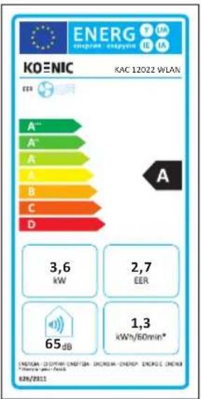
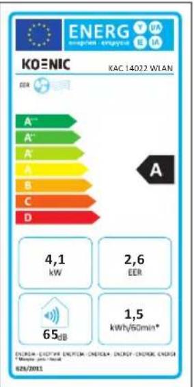
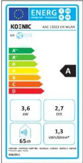
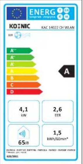
EU Product fiche |1/1
KAC 12022 WLAN/KAC 12022 CH WLAN
This product information is given in accordance with Annex I sect. 3 (d) of the Commission Regulation (EU) No 206/2012 implementing Directive 2009/125/EC of the European Parliament and of the Council with regard to ecodesign requirements for air conditioners and comfort fans.
Model identifier KAC 12022 WLAN/ KAC 12022 CH WLAN
| Symbol Value Unit | |||
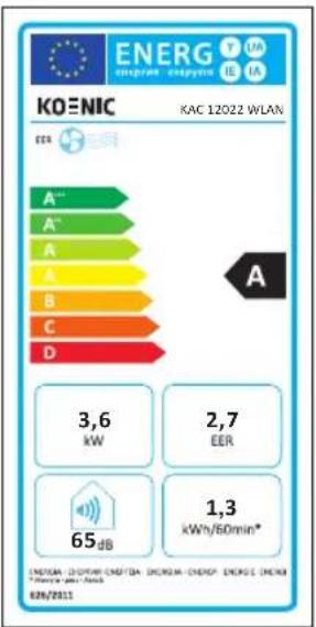
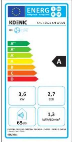
| Rated capacity for cooling P | rated for cooling | 3.6 kW | |
| Rated capacity for heating P | rated for heating | n/a kW | |
| Rated power input for cooling P | FER | 1.285 kW | |
| Rated power input for heating P | COP | n/a kW | |
| Rated energy efficiency ratio EER | d | 2.72 --- | |
| Rated Coefficient of performance COP | d | n/a --- | |
| Power consumption in thermostat-off mode P | TO | 10.6 | W |
| Power consumption in standby mode | PSB | 0.5 | W |
| Electricity consumption of double duct appliances (for cooling) | QDD for cooling | n/a | kWh/a |
| Electricity consumption of double duct appliances (for heating) | QDD for heating | n/a | kWh/a |
| Electricity consumption of single duct appliances (for cooling) | QSD for cooling | 1.285 | kWh/h |
| Electricity consumption of single duct appliances (for heating) | QSD for heating | n/a kWh/h | |
| Sound power level | LWA | 65 | dB(A) |
| Global warming potential | GWP | 3 | kg CO2 eq. |
| Contact details for obtaining more information | Imtron GmbHWankelstraße 585046 Ingolstadt, Germany | ||
English
EU Product fiche
1/1
KAC 14022 WLAN/KAC 14022 CH WLAN
This product information is given in accordance with Annex I sect. 3 (d) of the Commission Regulation (EU) No 206/2012 implementing Directive 2009/125/EC of the European Parliament and of the Council with regard to ecodesign requirements for air conditioners and comfort fans.
Model identifier KAC 14022 WLAN/ KAC 14022 CH WLAN
| Symbol Value Unit | |||
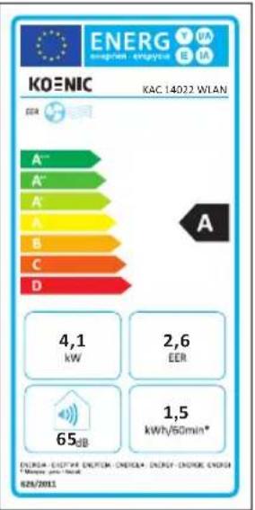
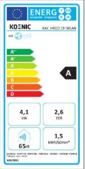
| Rated capacity for cooling P | rated for cooling | 4.1 kW | |
| Rated capacity for heating P | rated for heating | n/a kW | |
| Rated power input for cooling P | EER | 1.52 kW | |
| Rated power input for heating P | COP | n/a kW | |
| Rated energy efficiency ratio EER | d | 2.6 --- | |
| Rated Coefficient of performance COP | d | n/a --- | |
| Power consumption in thermostat-off mode P | TO | 10.6 W | |
| Power consumption in standby mode | PSB | 0.5 | W |
| Electricity consumption of double duct appliances (for cooling) | QDD for cooling | n/a | kWh/a |
| Electricity consumption of double duct appliances (for heating) | QDD for heating | n/a | kWh/a |
| Electricity consumption of single duct appliances (for cooling) | QSD for cooling | 1.52 | kWh/h |
| Electricity consumption of single duct appliances (for heating) | QSD for heating | n/a kWh/h | |
| Sound power level | LWA | 65 | dB(A) |
| Global warming potential | GWP | 3 | kg CO2 eq. |
| Contact details for obtaining more information | Imtron GmbHWankelstraße 585046 Ingolstadt, Germany | ||
The rated cooling capacity was tested under following conditions:
| Cooling operation | Indoor 3 | 5 °C (DB) 24 | °C (WB) |
Note:
- This product contains non-fluorinated greenhouse gas (hermetically sealed) which is dangerous for the environment and contributes to global warming if released to the atmosphere.
• Refrigerant type: R290
• Global warming potential (GWP): 3 - Refrigerant leakage contributes to climate change. Refrigerants with lower global warming potential (GWP) would contribute less to global warming than a refrigerant with higher GWP, if leaked to the atmosphere.
- This product contains a refrigerant fluid with a GWP equal to 3. This means that if 1 kg of this refrigerant fluid would be leaked to the atmosphere, the impact on global warming would be 3 times higher than 1 kg of CO₂, over a period of 100 years. Never try to interfere with the refrigerant circuit yourself or disassemble the product yourself and always ask a professional.
• Energy consumption 1,300 kWh (KAC 12022 WLAN/ KAC 12022 CH WLAN), 1,500 kWh (KAC 14022 WLAN/ KAC 14022 CH WLAN) per 60 minutes, based on standard test results. Actual energy consumption will depend on how the product is used and where it is located.
Wiring diagram
See annex.
Español
Draagbare airconditioners
EU Productfiche | 1/1
KAC 12022 WLAN/ KAC 12022 CH WLAN
Väggmontering (Del: N, O, P)
flowchart
graph TD
    A["Main PCB Assembly"] --> B["Main PCB Assembly"]
    B --> C["Factory Wiring"]
    C --> D["Display PCB Assembly"]
    D --> E["CN1"]
    D --> F["CN2"]
    D --> G["J4 WIFI"]
    D --> H["J3 DISPLAY"]
    D --> I["J9 IPT RT(L)"]
    D --> J["J16"]
    D --> K["J5 LEVEL1"]
    D --> L["J2 STEP MOTOR"]
    D --> M["Step Motor"]
    M --> N["BL"]
    M --> O["Reversing Valve"]
    M --> P["SO Box"]
    P --> Q["BL/WH"]
    P --> R["Power Supply"]
    P --> S["BR/BX"]
    P --> T["BR/RX"]
    P --> U["Capacitor"]
    P --> V["Upper Motor"]
    P --> W["FUSE"]
    W --> X["PADDLE-1"]
    W --> Y["J12"]
    W --> Z["N-5"]
    W --> AA["RD CAPACITOR"]
    W --> AB["BR CAPACITOR"]
    W --> AC["Ground"]
    subgraph Main PCB Assembly
        AD["Main PCB Assembly"] --> AE["ON/OFFAN-L(PUMP) J14"]
        AD --> AF["ON/OFFAN-H"]
        AD --> AG["OPTION PART"]
        AD --> AH["OPTION PART"]
        AD --> AI["ON/OFFAN-L(PUMP) J13"]
        AD --> AJ["ON/OFFAN-H"]
        AD --> AK["OPTION PART"]
        AD --> AL["ON/OFFAN-L(PUMP) J14"]
        AD --> AM["ON/OFFAN-H"]
        AD --> AN["OPTION PART"]
        AD --> AO["ON/OFFAN-L(PUMP) J13"]
        AD --> AP["ON/OFFAN-H"]
        AD --> AQ["OPTION PART"]
        AD --> AR["ON/OFFAN-L(PUMP) J14"]
        AD --> AS["ON/OFFAN-H"]
        AD --> AT["OFFAN-L(PUMP) J14"]
        AD --> AU["OFFAN-H"]
        AD --> AV["NO. COM. NO."]
        AD --> AW[BL/WH BL/WH BL/WH BL/WH BL/WH BL/WH BL/WH BL/WH BL/WH BL/WH BL/WH BL/WH BL/WH BL/WH BL/WH BL/WH BL/WH BL/WH BL/WH BL/WH BL/WH BL/WH BL/WH BL/WH BL/WH BL/WH BL/WH BL/WH BL/WH BL/WH BL/WH BL/WH BL/WH BL/WH BL/H
    end
    style Main PCB Assembly fill:#f9f,stroke:#333
    style Factory Wiring fill:#ccf,stroke:#333
    style Equipment & Component Structure
    note right of main PCB Assembly: THERMISTOR (AIR+PIPE)
    note left of main PCB Assembly: THERMISTOR (AIR+PIPE)
    note right of main PCB Assembly: THERMISTOR (AIR+PIPE)
    note left of main PCB Assembly: THERMISTOR (AIR+PIPE)
    note right of main PCB Assembly: THERMISTOR (AIR+PIPE)
    note left of main PCB Assembly: THERMISTOR (AIR+PIPE)
    note right of main PCB Assembly: THERMISTOR (AIR+PIPE)
    note left of main PCB Assembly: TERRIMATOR
    note right of main PCB Assembly: TERRIMATOR
    note left of main PCB Assembly: TERRIMATOR
    note right of main PCB Assembly: TERRIMATOR
    note left of main PCB Assembly: TERRIMATOR
    note right of main PCB Assembly: TERRIMATOR
    note left of main PCB Assembly: TERRIMATOR
    note right of main PCB Assembly: TERRIMATOR
    note left of main PCB Assembly: TERRIMATOR
    note right of main PCB Assembly: Step Motor
    note left of main PCB Assembly: Step Motor
    note right of main PCB Assembly: Step Motor
    note left of main PCB Assembly: Step Motor
    note right of main PCB Assembly: Step Motor
    note left of main PCB Assembly: Step Motor
    note right of main PCB Assembly: Step Motor
    note left of main PCB Assembly: Step Motor
    note right of main PCB Assembly: Step Motor
    note left of main PCB Assembly: Step Motor
    note right of main PCB Assembly: Step Motor
- Sicherheitshinweise
- English
- Safety instructions
- Warnings (concerning the R290 refrigerant)
- • Detection of flammable refrigerants
- Note about non fluorinated gases
- Congratulations!
- Intended use
- Before first time use
- Disposal
- Delivery Content
- Technical data
- KAC 12022 WLAN
- KAC 14022 WLAN
- Declaration of conformity
- Impedance Information:
- Controls and components
- A Remote control
- Control panel
- Auto/Low/Med/High
- Installation
- Placement
- Note:
- Air exhaust
- Wall mounting (Part: N, O, P)
- Window installation (Part: N, O, Q)
- Recommendation:
- Drainage hose
- Operation
- Fig. 5 Switching on/off
- Remote control
- Mode
- Warning
- Fig. 7 Setting the temperature
- Fig. 9 Air outlet adjustment
- Setting the timer
- Product panel
- Switch-on time
- Switch-off time
- Fig. 10 Activation and deactivation of WiFi
- Installation and use of WLAN/IoT functions
- Fig. 11 Water drainage
- Emptying the internal tank
- Cleaning & care
- Decommissioning
- Transportation
- Troubleshooting
- Information requirements
- Wiring diagram
- Español
- Väggmontering (Del: N, O, P)
Brand : Koenic
Model : KAC 14022
Category : Air Conditioning