USER MANUAL SS1287 Sogo
natural_image
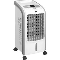
White CoolComfort air conditioner unit with control panel and external-mounted remote (no visible text or symbols on device body)

Aire Acondicionado Portátil Local Air Conditioner Climatiseur Portatif
O Condicionador De Ar Portátil Tragbarer Klimaanlage Condizionatore D'aria Portatile
Caution: please read and preserve these important instructions
natural_image
Line drawing of an air conditioner unit connected to a wall-mounted air outlet (no text or symbols)
natural_image
Line drawing of an air conditioner unit connected to a window, no text or symbols present
Aviso importante
natural_image
Line drawing of a portable air conditioner unit with ventilation grilles and control panel (no text or symbols)
natural_image
Line drawing of a portable air conditioner unit with a bucket and hose, no text or symbols present
Mantenimiento
natural_image
Line drawing of a large industrial air conditioning unit with cooling fans and wheels (no text or symbols)
Thank you for choosing the luxurious and elegant mobile air conditioning. Please keep the manual for later review, and read the manual carefully before use. This manual can also be downloaded from our webpage www.sogo.es
Notes:
- The air conditioning is only suitable for indoor use, and is not suitable for other applications.
- Follow local grid interconnection rules while installing the air conditioning and ensure that it is properly grounded. If you have any question on electrical installation, follow the instructions of the manufacturer, and if necessary, ask a professional electrician to install it.
- Place the machine in a flat and dry place and keep a distance of above 50cm between the machine and the surrounding objects or walls.
- After the air conditioning is installed, ensure that the power plug is intact and firmly plugged into the power outlet, and place the power cord orderly to prevent someone from being tripped or pulling out the plug.
- Do not put any object into the air inlet and outlet of the air conditioning. Keep the air inlet and outlet free from obstructions.
- When drainage pipes are installed, ensure that the drainage pipes are properly connected, and are not distorted or bended.
- While adjusting the upper and lower wind-guide strips of the air outlet, pluck it with hands gently to avoid damaging wind-guide strips.
- When moving the machine, make sure that it is in an upright position.
- The machine should stay away from gasoline, flammable gas, stoves and other heat sources.
- Don’t disassemble, overhaul and modify the machine arbitrarily, otherwise it will cause a machine malfunction or even bring harm to persons and properties. To avoid danger, if a machine failure occurs, ask the manufacturer or professionals to repair it.
- Do not install and use the air conditioning in the bathroom or other humid environments.
- Do not pull the plug to turn off the machine.
- Do not place cups or other objects on the body to prevent water or other liquids from spilling into the air conditioning.
- Do not use insecticide sprays or other flammable substances near the air conditioning.
- Do not wipe or wash the air conditioning with chemical solvents such as gasoline and alcohol. When you need to clean the air conditioning, you must disconnect the power supply, and clean it with a half-wet soft cloth. If the machine is really dirty, scrub with a mild detergent.
- The appliance can be used by children aged from 8 years and above and persons with reduced physi-
cal, sensory or mental capabilities if they have been given supervision or instruction concerning use of the appliance in a safe way and understand the hazards involved. Children shall not play with the appliance. Cleaning and maintenance shall not be made by children without supervision.
- Please make sure that the voltage of this appliance matches correctly to the voltage being used in your place of usage. Any damage to the appliance caused by connection error is out of scope fo the product warranty.
- The appliance shall be installed in accordance with your national wiring regulations. Please consult a professional electrician if you have any doubts regarding this.
- If the supply cord is damaged, it must be replaced by manufacturer, its service agent or similarly qualified persons in order to avoid a hazard.
Please safekeep this user's manual for future use.
-
Do not use means to accelerate the defrosting process or to clean, other than those recommended by the manufacturer.
-
The appliance shall be stored in a room without continuously operating ignition sources (for example: open flames, an operating gas appliance or an operating electric heater.)
-
Do not pierce ór burn.
-
Be aware that refrigerants may not contain an odour.
-
Appliance shall be installed, operated and stored in a room with a floor area larger than 12 m2
-
Keep any required ventilation openings clear of obstruction;
-
Servicing shall be performed only as recommended by the manufacturer.
-
The appliance shall be stored in a well-ventilated area where the room size corresponds to the room area as specified for operation.
-
Any person who is involved with working on or breaking into a refrigerant circuit should hold a current valid certificate from an industry-accredited assessment authority, which authorizes their competence to handle refrigerants safely in accordance with an industry recognized assessment specification.
-
Servicing shall only be performed as recommended by the equipment manufacturer. Maintenance and repair requiring the assistance of other skilled
personnel shall be carried out under the supervision of the person competent in the use of flammable refrigerants.
- All working procedure that affects safety means shall only be carried by competent persons.
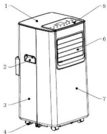
Features and Components
1.Features
New look, compact structure, streamlined machine, aristocratic atmosphere.
With cooling, dehumidification and fan function, Continuous Water Drainage Functions.
LED displays the control panel. The machine is beautiful and elegant. High-quality remote control is equipped to facilitate operation. It adopts a user-friendly remote control design.
Outdoor interface is set high to facility assembly and keep the smooth flow of the heat pipe.
Air filtration capability.
Timing switch function,
Protection function of automatically restarting the compressor after three minutes, a variety of other protection functions.
Installation and Adjustment
1. Installation:
Warning: before using the mobile air conditioning, keep it upright for at least two hours.
The air conditioning can be easily moved in the room. In the moving process, ensure that the air conditioning is in the upright position and the air conditioning should be placed on a flat surface. Do not install and use the air conditioning in the bathroom or other humid environments.
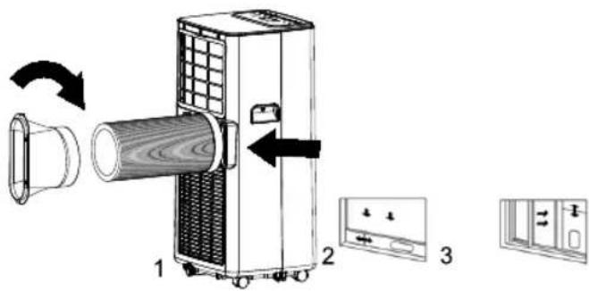
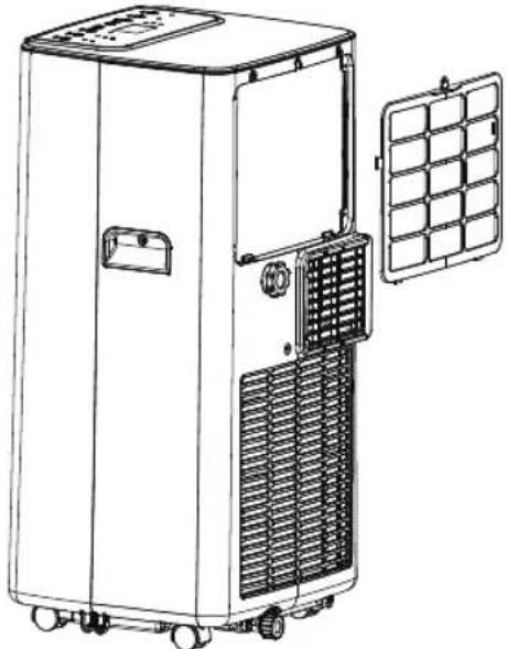
1.1 Install the heat pipe assembly (as shown in Fig.1): screw the heat pipe assembly (exhaust fitting end) into the exhaust port on the rear panel.
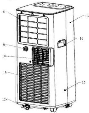
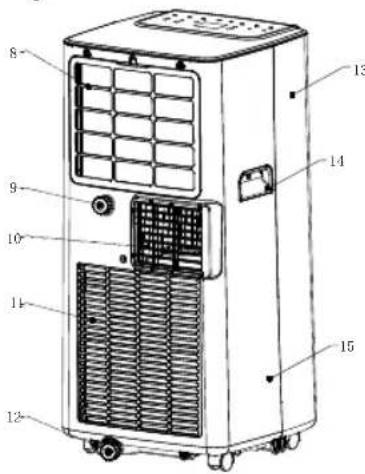
Components:
-
Top Cover
-
Handle
-
Rear Housing
-
Caster
-
Control Panel
-
Air outlet / Louver
-
Front Housing
-
EVA Filter
9.Continuous Drainage Hole
-
Air Vent
-
Con Filter
-
Drainage Hole
13.Front Housing
-
Handle
-
Rear Housing
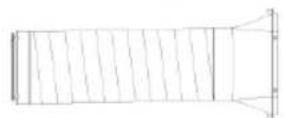
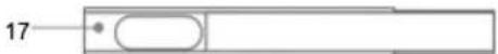
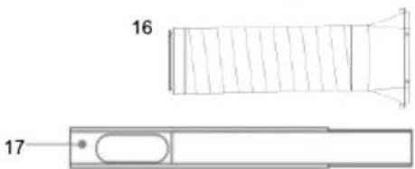
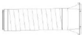
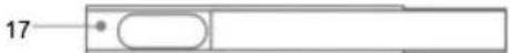
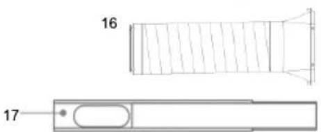
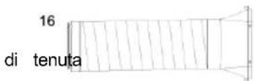
16.Exhaust Pipe Assembly
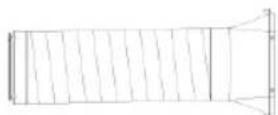
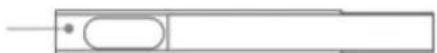
- Window Sealing Plate Assembly

natural_image
Technical line drawing of a mechanical component with two views (16 and 17), no text or symbols present.
1.2 Install the window sealing plate assembly
1) Half open the window, and mount the window sealing plate assembly to the window (as shown in Fig.2 and Fig.3); the assembly can be placed in horizontal and vertical direction.
2) Pull various components of the window sealing plate assembly open, adjust their opening distance to bring both ends of the assembly into contact with the window frame, and fix various components of the assembly.1.2 Install the window sealing plate assembly
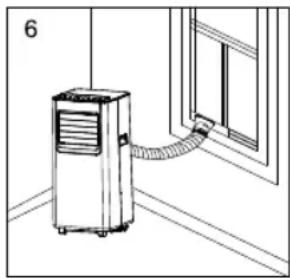
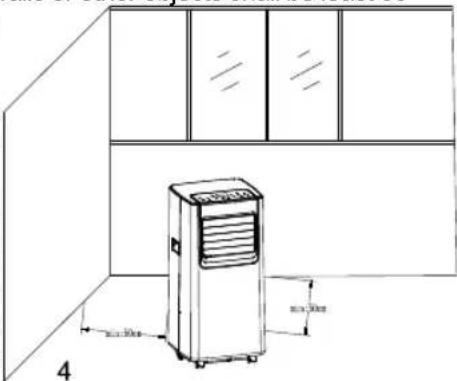
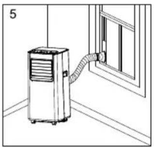
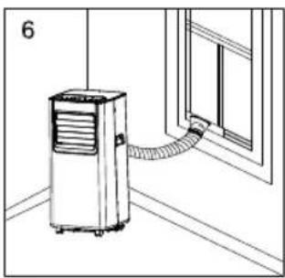
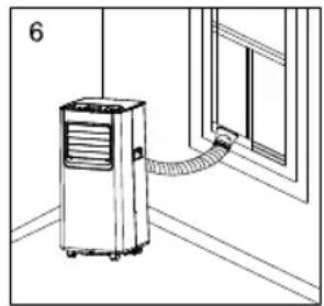
1.3 Install the body
1) Move the machine with installed heat pipe and fittings before the window, and the distance between the body and walls or other objects shall be least 50
cm (as shown in Fig.4).
2) Elongatethe exhaust pipe and snap the flat end of the exhaust pipe joints into the hole of the window sealing plate assembly (as
natural_image
Line drawing of a kitchen appliance cabinet with a mounted air conditioner unit, showing dimensions (no text or symbols)
shown in Fig.5 and Fig.6).
Notes: 1. the flat end of the exhaust pipe joints must be snapped into place.
- The pipe cannot be distorted nor has substantial turning (greater than 45°). Keep the ventilation of the exhaust pipe not blocked.
natural_image
Line drawing of an air conditioner unit connected to a window, no text or symbols present
natural_image
Line drawing of an air conditioner unit connected to a window, no text or symbols present
Important Notice
The length of the exhaust hose shall be 280\~1,500mm, and this length is based on the specifications of the air conditioning. Do not use extension tubes or replace it with other different hoses, or this may cause a malfunction. Exhaust host must be not blocked; otherwise it may cause overheating.
Control Panel Setting
I. Operating instructions:
LED Control Panel is as follows:
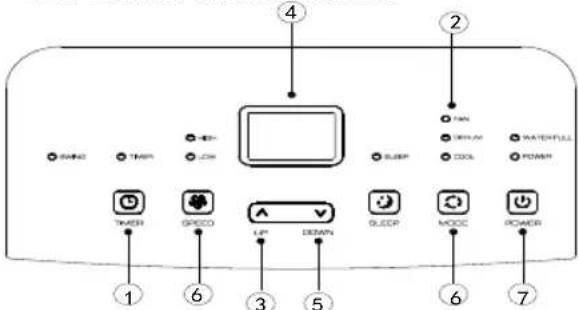
- Timer Key
- Fan Speed Selection Key
- Up Key
- Display Window
- Down Key
- Mode Selection Key
- Power Key
1: When the machine is powered on for the first time, the buzzer will play power-on music, and then the machine will get into standby status.
2: Power Key: press the key to turn on and turn off the machine. In the case of power on, press the key to turn off the machine; in the case of power off, press the key to turn on the machine.
3: ModeSelection Key: In the case of power on, press the key to switch between cooling → fan →
dehumidifying mode.
4: Up Key and Down Key: press the two keys to change the setting temperature or setting time, operate as follows:
While setting temperature, press up key or down key to select the required temperature (not available in fan or dehumidifying mode).
While setting time, press up key or down key to select the required time.
5: Wind Speed Selection Key:
In cooling and fan mode, press the key to select high, low wind speed operation. But limited by anti-cold conditions, under certain conditions, it may not run according to the set wind speed.
In dehumidifying mode, pressing the key is invalid, and the fan will forcibly choose low wind speed operation.
6: Timing Key:
In the case of power on, press the key to close timing; in the case of power off, press the key to open timing. Press the key, when the timing symbol flashes, press up and down key to select the required timing value.
Timing values can be set in 1-24 hours and the timing value is adjusted up or down by one hour.
7: Sleep Mode:
In the cooling, Mode, Press the UP and Fan Key to turn on the sleep mode, then the unit will work on Energy-Saving and quiet type.
Note: Cannot turn on the sleep mode in the dehumidifying or Fan mode!
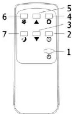
II. Operating Instructions of the Remote Control
The remote-control Panel is as follows:
Instructions of key operation of the high-quality remote control are as follows:
- Power: Press the key to turn on or turn off the machine.
- Timer: press the key to set timing.
- Down: press the key to reduce temperature and timing set value.
- Mode: press the key to switch ▲ between cooling, fan, dehumidifying mode.
- Up: press the key to increase temperature and timing set value.
- Fan: press the key to select high, low wind speed.
- Sleep Mode: Press the key to turn on the sleep mode.
III. A Variety of Protection Functions
3.1 Frost Protection Function:
In cooling, dehumidifying or economic power saving mode, if the temperature of the exhaust pipe is too low, the machine will automatically enter protection status; if the temperature of the exhaust pipe rises to a certain temperature, it can automatically revert to normal operation.
3.2 Overflow Protection Function:
When water in the water pan exceeds the warning level, the machine will automatically sound an alarm, and the "FULL" indicator light will flash. At this point, you need to move the drainage pipe connecting the machine or the water outlet to sewer or other drainage area to empty the water (details see Drainage Instructions at the end of this chapter). After the water is emptied, the machine will automatically return to the original state.
3.3 Automatic Defrosting (cooling models have this function):
The machine has automatic defrosting function.
3.4. Protection Function of the Compressor
To increase the service life of the compressor, it has a 3-minute delay booting protection function after the compressor is turned off.
Drainage Instructions
1. Manual drainage:
1) When the machine stops after the water is full, turn off the machine power and unplug the power plug.
Notes: Please move the machine carefully, so as not to spill the water in the water pan at the bottom of the body.
2) Place the water container below the side water outlet behind the body.
3) Unscrew the drainage cover and unplug the water plug, the water will automatically flow into the water container.
Notes:
-
Keep the drainage cover and the water plug properly.
-
During drainage, the body can be tilted slightly backwards.
-
If the water container cannot hold all the water, before the water container is full, stuff the water outlet with the water plug as soon as possible to prevent water from flowing to the floor or the carpet.
4) When the water is discharged, stuff the water plug, and tighten the drainage cover.
Notes: 1. Restart the machine after the water plug and drainage cover are installed, otherwise condensate water of the machine will flow to the floor or the carpet.
natural_image
Line drawing of an air conditioner unit with ventilation grilles and control panel (no text or symbols)
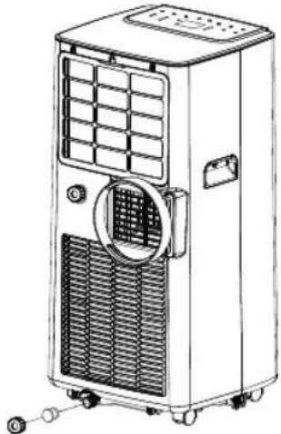
- Continuous drainage (Optional) (only applicable to cooling and dehumidifying mode), as shown in figure:
1) Unscrew the drainage cover, and unplug the water plug.
2) Set the drainage pipe into the water outlet.
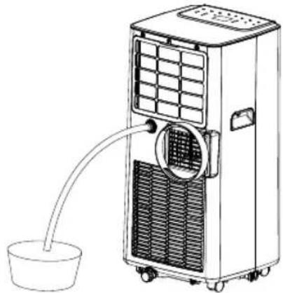
natural_image
Line drawing of a portable air conditioner unit with a bucket and piping (no text or symbols)
3) Connect the drainage pipe to the bucket.
Maintenance
Cleaning: before cleaning and maintenance, turn off the machine and unplug the plug.
1. Clean the surface
Clean with surface of machine with a wet soft cloth. Don't use chemicals, such as benzene, alcohol, gasoline, etc.; otherwise, the surface of the air conditioning will be damaged or even the whole machine will be damaged.
2. Clean the filter screen
If the filter screen is clogged with dust, and the effectiveness of the air conditioning is reduced, be sure to clean the filter screen once every two weeks.
2.1: Clean the upper filter screen frame
1) Clasp the wedging block of the EVA filter screen frame with hands. Force down from the outside to remove the EVA filter screen frame. Unscrew four screws fixing the EVA filter screen and the rear housing to remove the EVA filter screen (as shown in the above figure).
2) Put the EVA filter screen into warm water with neutral detergent (about 40□ / 104□) and dry it in the shade after rinsing clean.
Unit Storage:
1: Unscrew the drainage cover, unplug the water plug, and discharge the water in the water pan into other water containers or directly tilt the body to discharge the water into other containers.
2: Turn on the machine, adjust it to low-wind ventilation mode, and maintain this state until the drainage pipe becomes dry, so as to keep the inside of the body in a dry state and prevent it from mildewing.
3: Turn off the machine, unplug the power plug, and wrap the power cord around the wrapping post; install the water plug and the drainage cover.
4: Remove the exhaust pipe and keep it properly.
5: Cover the air conditioning with a plastic bag. Put the air conditioning in a dry place, keep it out of the reach of children, and take dust control measures.
6: Remove batteries of the remote control and keep them properly.
natural_image
Line drawing of a large industrial air conditioning unit with cooling fans and ventilation grilles (no text or symbols)
Note: ensure that the body is placed in a dry place and keep all machine components properly.
Troubleshooting
Do not repair or disassemble the air conditioning by yourself. Unqualified repair will lead to failure of the warranty card, and may cause damage to users or their properties. In case of the malfunction, please check the list below to find out if the problem can be solved with few simple steps. If this doesnt solve your problem then take the unit to our authorized service center.
| Problems Reasons | Solutions | |
| The air conditioning does not work. | There is no electricity. | Turn it on after connecting it to a socket with electricity. |
| The overflow indicator displays “FL”. | Discharge the water inside. |
| The ambient temperature is too low or too high | Recommend to use the machine in at the temperature of 7-35 (44-95). |
| In cooling mode, the room temperature is lower than the set temperature; in heating mode, the room temperature is higher than the set temperature. | Change the set temperature. |
| In dehumidification mode, the ambient temperature is low. | The machine is placed in a room with an ambient temperature of greater than 17 (62). |
| The cooling effect is not good | There is direct sunlight. Pull the Curtain. |
| Doors or windows are open; there are a lot of people; or in cooling mode, there are other sources of heat. | Close doors and windows, and add new air conditioning. |
| The filter screen is dirty. | Clean or replace the filter screen. |
| The air inlet or outlet is blocked. | Clear obstructions. |
| Big Noise | The air conditioning is not placed on a flat surface. | Put the air conditioning on a flat and hard place (to reduce noise). |
| compressor does not work. | Overheat protection starts. | Wait for 3 minutes until the temperature is lowered, and then restart the machine. |
| The remote control does not work. | The distance between the machine and the remote control is too far. | Let the remote control get close to the air conditioning, and make sure that the remote control directly faces to the direction of the remote control receiver. |
| The remote control is not aligned with the direction of the remote control receiver. |
| Batteries are dead. Replace batteries. | |
| Displays ‘E1’. | The pipe temperature sensor is abnormal. | Check the pipe temperature sensor and related circuitry. |
| Displays ‘E2’ | The room temperature sensor is abnormal. | Check the room temperature sensor and related circuitry. |
Note: If problems not listed in the table occur or recommended solutions do not work, please contact the professional service organization.
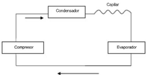
Schematic Diagram
All the technical and specific parameters, please refer to product nameplate.
Due to continuous improvement, we reserve the right to change some design without any notice.
1) Checks to the area
Prior to beginning work on systems containing flammable refrigerants, safety checks are necessary to ensure that the risk of ignition is minimised. For repair to the refrigerating system, the following precautions shall be complied with prior to conducting work on the system.
2) Work procedure
Work shall be undertaken under a controlled procedure so as to minimise the risk of a flammable gas or vapour being present while the work is being performed.
3) General work area
All maintenance staff and others working in the local area shall be instructed on the nature of work being carried out. Work in confined spaces shall be avoided. The area around the workspace shall be sectioned off. Ensure that the conditions within the area have been made safe by control of flammable material.
4) Checking for presence of refrigerant
The area shall be checked with an appropriate refrigerant detector prior to and during work, to ensure the technician is aware of potentially flammable atmospheres. Ensure that the leak detection equipment being used is suitable for use with flammable refrigerants, i.e. non-sparking, adequately sealed or intrinsically safe.
5) Presence of fire extinguisher
If any hot work is to be conducted on the refrigeration equipment or any associated parts, appropriate fire extinguishing equipment shall be available to hand. Have a dry powder or CO2 fire extinguisher adjacent to the charging area.
6) No ignition sources
No person carrying out work in relation to a refrigeration system which involves exposing any pipe work that contains or has contained flammable refrigerant shall use any sources of ignition in such a manner that it may lead to the risk of fire or explosion. All possible ignition sources, including cigarette smoking, should be kept sufficiently far away from the site of installation, repairing, removing and disposal, during which flammable refrigerant can possibly be released to the surrounding space. Prior to work taking place, the area around the equipment is to be surveyed to make sure that there are no flammable hazards or ignition risks. “No Smoking” signs shall be displayed.
7) Ventilated area
Ensure that the area is in the open or that it is adequately ventilated before breaking into the system or conducting any hot work. A degree of ventilation shall continue during the period that the work is carried out. The ventilation should safely disperse any released refrigerant and preferably expel it externally into the atmosphere.
8) Checks to the refrigeration equipment
Where electrical components are being changed, they shall be fit for the purpose and to the correct specification. At all times the manufacturer's maintenance and service guidelines shall be followed. If in doubt consult the manufacturer's technical department for assistance.
The following checks shall be applied to installations using flammable refrigerants:
– The charge size is in accordance with the room size within which the refrigerant containing parts are installed;
– The ventilation machinery and outlets are operating adequately and are not obstructed;
- If an indirect refrigerating circuit is being used, the secondary circuit shall be checked for the presence of refrigerant;
- Marking to the equipment continues to be visible and legible. Markings and signs that are illegible shall be corrected;
– Refrigeration pipe or components are installed in a position where they are unlikely to be exposed to any substance which may corrode refrigerant containing components, unless the components are constructed of materials which are inherently resistant to being corroded or are suitably protected against being so corroded.
9) Checks to electrical devices
Repair and maintenance to electrical components shall include initial safety checks and component inspection procedures. If a fault exists that could compromise safety, then no electrical supply shall be connected to the circuit until it is satisfactorily dealt with. If the fault cannot be corrected immediately but it is necessary to continue operation, an adequate temporary solution shall be used. This shall be reported to the owner of the equipment so all parties are advised. Initial safety checks shall include:
- That capacitors are discharged: this shall be done in a safe manner to avoid possibility of sparking;
- That there no live electrical components and wiring are exposed while charging, recovering or purging the system;
- That there is continuity of earth bonding.
REPAIRS TO SEALED COMPONENTS
1) During repairs to sealed components, all electrical supplies shall be disconnected from the equipment being worked upon prior to any removal of sealed covers, etc. If it is absolutely necessary to have an electrical supply to equipment during servicing, then a permanently operating form of leak detection shall be located at the most critical point to warn of a potentially hazardous situation.
2) Particular attention shall be paid to the following to ensure that by working on electrical components, the casing is not altered in such a way that the level of protection is affected. This shall include damage to cables, excessive number of connections, terminals not made to original specification, damage to seals, incorrect fitting of glands, etc.
Ensure that apparatus is mounted securely. Ensure that seals or sealing materials have not degraded such that they no longer serve the purpose of preventing the ingress of flammable atmospheres. Replacement parts shall be in accordance with the manufacturer's specifications.
NOTE: The use of silicon sealant may inhibit the effectiveness of some types of leak detection equipment. Intrinsically safe components do not have to be isolated prior to working on them.
REPAIR TO INTRINSICALLY SAFE COMPONENTS
Do not apply any permanent inductive or capacitance loads to the circuit without ensuring that this will not exceed the permissible voltage and current permitted for the equipment in use.
Intrinsically safe components are the only types that can be worked on while live in the presence of a flammable atmosphere. The test apparatus shall be at the correct rating. Replace components only with parts specified by the manufacturer. Other parts may result in the ignition of refrigerant in the atmosphere from a leak.
CABLING
Check that cabling will not be subject to wear, corrosion, excessive pressure, vibration, sharp edges or any other adverse environmental effects. The check shall also take into account the effects of aging or continual vibration from sources such as compressors or fans.
DETECTION OF FLAMMABLE REFRIGERANTS
Under no circumstances shall potential sources of ignition be used in the searching for or detection of refrigerant leaks. A halide torch (or any other detector using a naked flame) shall not be used.
LEAK DETECTION METHODS
The following leak detection methods are deemed acceptable for systems containing flammable refrigerants.
Electronic leak detectors shall be used to detect flammable refrigerants, but the sensitivity may not be adequate, or may need re-calibration. (Detection equipment shall be calibrated in a refrigerant-free area.) Ensure that the detector is not a potential source of ignition and is suitable for the refrigerant used. Leak detection equipment shall be set at a percentage of the LFL of the refrigerant and shall be calibrated to the refrigerant employed and the appropriate percentage of gas (25 % maximum) is confirmed.
Leak detection fluids are suitable for use with most refrigerants but the use of detergents containing chlorine shall be avoided as the chlorine may react with the refrigerant and corrode the copper pipe-work.
If a leak is suspected, all naked flames shall be removed/ extinguished.
If a leakage of refrigerant is found which requires brazing, all of the refrigerant shall be recovered from the system, or isolated (by means of shut off valves) in a part of the system remote from the leak. Oxygen free nitrogen (OFN) shall then be purged through the system both before and during the brazing process.
REMOVAL AND EVACUATION
When breaking into the refrigerant circuit to make repairs – or for any other purpose – conventional procedures shall be used. However, it is important that best practice is followed since flammability is a consideration. The following procedure shall be adhered to:
- Remove refrigerant;
- Purge the circuit with inert gas;
- Evacuate;
- Purge again with inert gas;
- Open the circuit by cutting or brazing.
The refrigerant charge shall be recovered into the correct recovery cylinders. The system shall be "flushed" with OFN to render the unit safe. This process may need to be repeated several times. Compressed air or oxygen shall not be used for this task.
Flushing shall be achieved by breaking the vacuum in the system with OFN and continuing to fill until the working pressure is achieved, then venting to atmosphere, and finally pulling down to a vacuum. This process shall be repeated until no refrigerant is within the system. When the final OFN charge is used, the system shall be vented down to atmospheric pressure to enable work to take place. This operation is absolutely vital if brazing operations on the pipe-work are to take place. Ensure that the outlet for the vacuum pump is not close to any ignition sources and there is ventilation available.
CHARGING PROCEDURES
In addition to conventional charging procedures, the following requirements shall be followed.
- Ensure that contamination of different refrigerants does not occur when using charging equipment. Hoses or lines shall be as short as possible to minimise the amount of refrigerant contained in them.
– Cylinders shall be kept upright.
– Ensure that the refrigeration system is earthed prior to charging the system with refrigerant.
- Label the system when charging is complete (if not already).
– Extreme care shall be taken not to overfill the refrigeration system.
Prior to recharging the system it shall be pressure tested with OFN. The system shall be leak tested on completion of charging but prior to commissioning. A follow up leak test shall be carried out prior to leaving the site.
DECOMMISSIONING
Before carrying out this procedure, it is essential that the technician is completely familiar with the equipment and all its detail. It is recommended good practice that all refrigerants are recovered safely. Prior to the task being carried out, an oil and refrigerant sample shall be taken in case analysis is required prior to re-use of reclaimed refrigerant. It is essential that electrical power is available before the task is commenced.
a) Become familiar with the equipment and its operation.
b) Isolate system electrically.
c) Before attempting the procedure ensure that:
- Mechanical handling equipment is available, if required, for handling refrigerant cylinders;
- All personal protective equipment is available and being used correctly;
- The recovery process is supervised at all times by a competent person;
• Recovery equipment and cylinders conform to the appropriate standards.
d) Pump down refrigerant system, if possible.
e) If a vacuum is not possible, make a manifold so that refrigerant can be removed from various parts of the system.
f) Make sure that cylinder is situated on the scales before recovery takes place.
g) Start the recovery machine and operate in accordance with manufacturer's instructions.
h) Do not overfill cylinders. (No more than 80 % volume liquid charge).
i) Do not exceed the maximum working pressure of the cylinder, even temporarily.
j) When the cylinders have been filled correctly and the process completed, make sure that the cylinders and the equipment are removed from site promptly and all isolation valves on the equipment are closed off.
k) Recovered refrigerant shall not be charged into another refrigeration system unless it has been cleaned and checked.
LABELLING
Equipment shall be labelled stating that it has been de-commissioned and emptied of refrigerant. The label shall be dated and signed. Ensure that there are labels on the equipment stating the equipment contains flammable refrigerant.
RECOVERY
When removing refrigerant from a system, either for servicing or decommissioning, it is recommended good practice that all refrigerants are removed safely.
When transferring refrigerant into cylinders, ensure that only appropriate refrigerant recovery cylinders are employed. Ensure that the correct number of cylinders for holding the total system charge is available. All cylinders to be used are designated for the recovered refrigerant and labelled for that refrigerant (i.e. special cylinders for the recovery of refrigerant). Cylinders shall be complete with pressure relief valve and associated shut-off valves in good working order. Empty recovery cylinders are evacuated and, if possible, cooled before recovery occurs.
The recovery equipment shall be in good working order with a set of instructions concerning the equipment that is at hand and shall be suitable for the recovery of flammable refrigerants. In addition, a set of calibrated weighing scales shall be available and in good working order. Hoses shall be complete with leak-free disconnect couplings and in good condition. Before using the recovery machine, check that it is in satisfactory working order, has been properly maintained and that any associated electrical components are sealed to prevent ignition in the event of a refrigerant release. Consult manufacturer if in doubt.
The recovered refrigerant shall be returned to the refrigerant supplier in the correct recovery cylinder, and the relevant Waste Transfer Note arranged. Do not mix refrigerants in recovery units and especially not in cylinders.
If compressors or compressor oils are to be removed, ensure that they have been evacuated to an acceptable level to make certain that flammable refrigerant does not remain within the lubricant. The evacuation process shall be carried out prior to returning the compressor to the suppliers. Only electric heating to the compressor body shall be employed to accelerate this process. When oil is drained from a system, it shall be carried out safely.
Technical Specification:
| MODEL SS-1287 | |
| VOLTAGE / FREQUENCY 220 – 240V ~ 50Hz | |
| INPUT POWER | COOLING 880W |
| WAIRFLOW 300 M3/h | |
| MAXIMUM OPERATIVE PRESSURE PERMITTED SUCTION: 0.6 MPa |
| MAXIMUM OPERATIVE PRESSURE PERMITTED DISCHARGE: 1.8 MPa |
| MAXIMUM PRESSURE PERMITTED 3 MPa | |
| SERVICE VALUE 2.6 | |
| ENERGY CLASS A | |
| SOUND LEVEL | ≤ 65 db (max) |
| COOLING CAPACITY 8000 BTU/h (2.35KW) | |
| DEHUMIDIFIER 19L / Day | |
| REFRIGERANT / LOAD | R290 / 140g |
| NORM Class I | |
| POWER INPUT 2350W | |
| STANDBY POWER CONSUMPTION 0.48 | |
| MEASUREMENT STANDARD FOR SERVICE VALUE | IEC 60335-2-40:2002 |
ERP RÈGLEMENT (UE)
No 206/2012 DE LA
COMMISSION directive
2009/125 / CE

natural_image
Line drawing of an air conditioner unit connected to a window, no text or symbols present

natural_image
Line drawing of an air conditioner unit connected to a window, no text or symbols present
natural_image
Line drawing of a portable air conditioner unit with ventilation grilles and control panel (no text or symbols)
natural_image
Line drawing of a portable air conditioner unit with a bucket and piping (no text or symbols)
natural_image
Line drawing of a large industrial air conditioner unit with cooling fins and ventilation slots (no text or symbols)
COMMISSION directive
2009/125 / CE
Instalação e Ajuste
1. Instalação:
natural_image
Line drawing of an air conditioner unit connected to a window (no text or symbols)

natural_image
Line drawing of an air conditioner unit connected to a window, no text or symbols present
Aviso importante
natural_image
Line drawing of a portable air conditioner unit with ventilation grilles and control panel (no text or symbols)
natural_image
Line drawing of a portable air conditioner unit with a bucket and piping (no text or symbols)
natural_image
Line drawing of a portable industrial air conditioner unit with cooling fans and ventilation slots (no text or symbols)
natural_image
Four black-and-white icons: warning triangle with flame, open book, open icon with 'i', and open notebook with wrench (no text or symbols)
natural_image
Line drawing of an air conditioner unit connected to a window (no text or symbols)

natural_image
Line drawing of an air conditioner unit attached to a window, with no text or symbols present
Wichtiger Hinweis
natural_image
Line drawing of a portable air conditioner unit with ventilation grilles and control panel (no text or symbols)
natural_image
Line drawing of an air conditioner unit with a bucket and cooling fan (no text or symbols)
natural_image
Line drawing of a large industrial air conditioner unit with cooling fans and ventilation slots (no text or symbols)
natural_image
Line drawing of an indoor air conditioner unit in a kitchen with cabinet doors (no text or symbols)
natural_image
Line drawing of an air conditioner unit connected to a window (no text or symbols)
natural_image
Line drawing of an air conditioner unit connected to a wall-mounted hose (no text or symbols)
natural_image
Line drawing of a portable air conditioner unit with ventilation grilles and control panel (no text or symbols)
Note:
natural_image
Line drawing of a portable air conditioner unit with a bucket and piping (no text or symbols)
natural_image
Line drawing of a portable air conditioner unit with cooling fans and ventilation slots (no text or symbols)
This device complies with EU Low Voltage Directive 2014/35/EC.
Electromagnetic Compatibility Directive 2014/30/EU. Directive 2015/863/EU on the restriction of the use of certain hazardous substances in electrical.
Directive 2009/125/EC on the eco-design requirements applicable to energy-related products.


This symbol on the product or on the packaging indicates that this product can't be disposed as normal rubbish or household waste. All the electrical, electronic equipment's and battery-operated units must recycle in proper manner and according to the local municipal laws. You can recycle them by taking them to government authorized disposal centres or specialized bins which you can find in any nearby big super markets, electronics or electro domestics products stores or malls who have these types of facilities available.
Designed by: SOGO based on European quality standards
Imported by: Sanysan Appliances S.L, NIF: B98753056, C/ Barcas 2, 2, 46002 Valencia, Spain
Product manufactured in China After-sales service: www.sogosat.com sogosat@sogosat.com / 0034 902 222 161