SPLASMA 40 - Plasma welder Stamos - Free user manual and instructions
Find the device manual for free SPLASMA 40 Stamos in PDF.
User questions about SPLASMA 40 Stamos
0 question about this device. Answer the ones you know or ask your own.
Ask a new question about this device
Download the instructions for your Plasma welder in PDF format for free! Find your manual SPLASMA 40 - Stamos and take your electronic device back in hand. On this page are published all the documents necessary for the use of your device. SPLASMA 40 by Stamos.
USER MANUAL SPLASMA 40 Stamos
The operation manual must be reviewed.

Never dispose of electrical equipment together with household waste.

This machine conforms to CE declarations.

Use full body protective clothes.

Attention! Wear protective gloves.

Safety goggles must be worn.

Protective footwear must be worn.

Attention! Hot surface may cause burns.

Caution! Fire or explosion hazard.

Caution! Harmful vapours, risk of poisoning. Gases and vapours may be hazardous to your health. During the welding process, welding gases and vapours are released. Inhalation of these substances may be hazardous to health.

Use a welding mask with appropriate filter shading degree.

WARNING! Harmful radiation of welding arc.

PLEASE Drawings in this manual are for illustration purposes only and in some details may differ from the actual machine.
The original operation manual is in German. Other language versions are translations from German.
BEFORE TURNING THE DEVICE ON, READ THE INSTRUCTION MANUAL THOROUGHLY AND OBSERVE THE FOLLOWING GUIDELINES:
Familiarize yourself with the instruction manual and the device.
For your own safety and the one of third parties, observe the safety instructions and the guidelines specified in the manual. People under 18, as well as those who are unfamiliar with the instruction manual are not allowed to operate the device. The device may only be used in accordance with its purpose.
NOTE
- ensure your own safety and the one of third parties by reading and following the instructions of the device
- Only qualified persons can be allowed to use, operate and repair the device.
While the device is in use, keep third parties, particularly minors, away from the place of use.
CUTTING MAY CAUSE FIRE OR AN EXPLOSION
A plasma beam ejects incandescent metal particles or sparkles. Hot metal particles, sparks, heated elements or hot equipment may cause fire. Therefore, it is necessary to closely examine the work place surrounding sand to make sure if it is suitable as a working area before using the device.
- Remove all flammable materials within 12 m radius from the burner.
If that is not possible, the flammable materials are to be covered with an appropriate covering - It is forbidden to cut in places where flammable materials may be ignited.
- Use means of protection against stream of sparks and incandescent metal particles.
- Keep in mind that sparks or hot metal splinters may penetrate through gaps or openings.
Pay close attention to the electric arc and make sure a fire extinguisher is at hand. - Keep in mind that cutting close to a ceiling, on the floor or between partitioned space may cause a fire on the other, not visible side.
DO NOT WELD NEAR TANKS OR BARRELS WITH FLAMMABLE SUBSTANCES.
The power cable is to be plugged into the nearest socket and arranged in a practical and safe manner. Avoid careless arrangement of the cable in the room on untested floor, which may cause an electric shock or fire.
- Do not use the plasma cutter to defrost frozen pipes.
- Do not cut with plasma near flammable materials/containers. Flammable materials or containers are to be removed or thoroughly emptied.
- Do not cut with plasma in an atmosphere containing flammable particles or vapours of explosive materials.
- Do not plasma-cut pressurized tanks, pressure system pipes or pressurized containers.
It is forbidden to plasma-cut containers with flammable materials. - During plasma-cutting, it is required to wear clean, oil-free protective clothes, e.g.: leather gloves, thick shirt, high boots and protective hood.
The plasma cutting station is to be located away from flammable surfaces. - Before starting plasma-cutting, get rid of flammable or explosive objects, such as propane-butane lighters or matches.
- Observe safety and OHS regulations applicable to welding work and ensure the work station is equipped with an appropriate fire extinguisher. The flame and the working circuit are energized if the electric power supply is activated. The input and internal circuit of the device are also energized if the electric power supply is activated.
ELECTRIC SHOCK IS HAZARDOUS FOR LIFE AND HEALTH
- Do not touch energized elements.
- Wear dry, insulated gloves without any holes, as well as suitable protective clothes.
- Put insulation mats or other insulation coatings on the floor; which should be sufficiently large to prevent the body from touching the workpiece or the floor.
- Do not touch the electric arc if it touches the workpiece or the floor.
Before operating, cleaning or replacing the electrode, disconnect the electrical power supply. - Before the installation or maintenance, disconnect the power supply.
- Ensure that the grounding cable is properly grounded and the pin is properly connected to a grounded socket.
Always inspect carefully the grounding. - Before connecting the input, select an appropriate grounding.
- Inspect regularly the power if they are damage or if they present lack of insulation. A damaged cable must be replaced immediately. Cables must be replaced if any damage is found. Improper repair of the insulation may cause death or injury.
- Turn the device off when it is not used.
- Replace the cable if you notice any signs or abrasion or local damage.
Do not coil the cable around your body.
The welded workpiece is to be properly grounded. - Use only equipment in good condition.
Any damaged elements of the device are to be repaired or replaced.
During work at elevated heights, use safety harness - All the elements of equipment and safety should be located in one place.
It is forbidden to deactivate the safety system. - Use only pistols listed in the instruction manual.
When activating the release, keep the pistol tip and the arc as far as possible from your body. - Attach the working cable to an appropriate metal contact of the welded workpiece (not to an element which may fall off) or to the work table as close to the welder as seems appropriate.
The working clamp is to be insulated, unless it is connected to the workpiece, in order to avoid contact with metal.
EN
EN
After disconnecting the supply cable, the device may still contain SIGNIFICANT VOLTAGE.
After turning the device off and disconnecting the power cable, check the voltage on the input capacitor and ensure the voltage value is zero, otherwise do not touch any element of the device. The capacitors are to be inspected in accordance with the guidelines in the operation section of this manual.
ELECTRIC SHOCK may be lethal.
Unsecured elements of the rectifier may explode at the moment of turning on the power supply. When using the rectifier, always use a protective mask and working clothes with long sleeves.
EXPLODING PARTS OF THE DEVICE may cause injury.
Metal splinters during welding constitute a health hazard.
SPLINTERS AND SPARKS may cause injuries.
Always wear a protective mask with side shield.
Always wear appropriate protective clothes in order to protect your body.
Always wear earplugs or other hearing protection in order to prevent the splinters from entering your car.
- During welding, the electric arc generates significant amount of visible and invisible radiation (UV and IR radiation) which may damage eyesight and skin
ELECTRIC ARC RADIATION may damage eyesight and skin.
- Always use face protection (helmet or shield) and eye protection with glass with appropriate tint. acting as filter and protecting the eyes during cutting.
- Safety standards propose tint no. 9 (no.8 at minimum) for every current intensity below 300 A.A lower shield tint may be used if the arc covers the workpiece.
Always use permitted safety goggles with side shield under the helmet or another protection.
Use workplace shields in order to protect other people against blinding light or splinters. Warn bystanders not to look at the electric arc. - Use protective clothes made of non-flammable and non-conductive material (leather, thick wool or cotton) and appropriate working footwear.
THERMAL PROTECTION
The thermal protection system is activated when the device exceeds the activation time. It causes the device to switch off. The status indicator on the front panel glows. The fan works until the device is cooled. After cooling the device to the operational temperature, it can be restarted.
DUTY CYCLE
The duty cycle is the percentage of the operating time (measured in minutes) of a 10-minute period in which the machine is used continuously in normal temperature conditions. If the values of the duty cycle are exceeded, this will trigger the overheat protection function, which stops the machine until it is cooled down to normal operating temperature. Repeated situations of exceeding the duty cycle values may lead to serious damage of the machine.
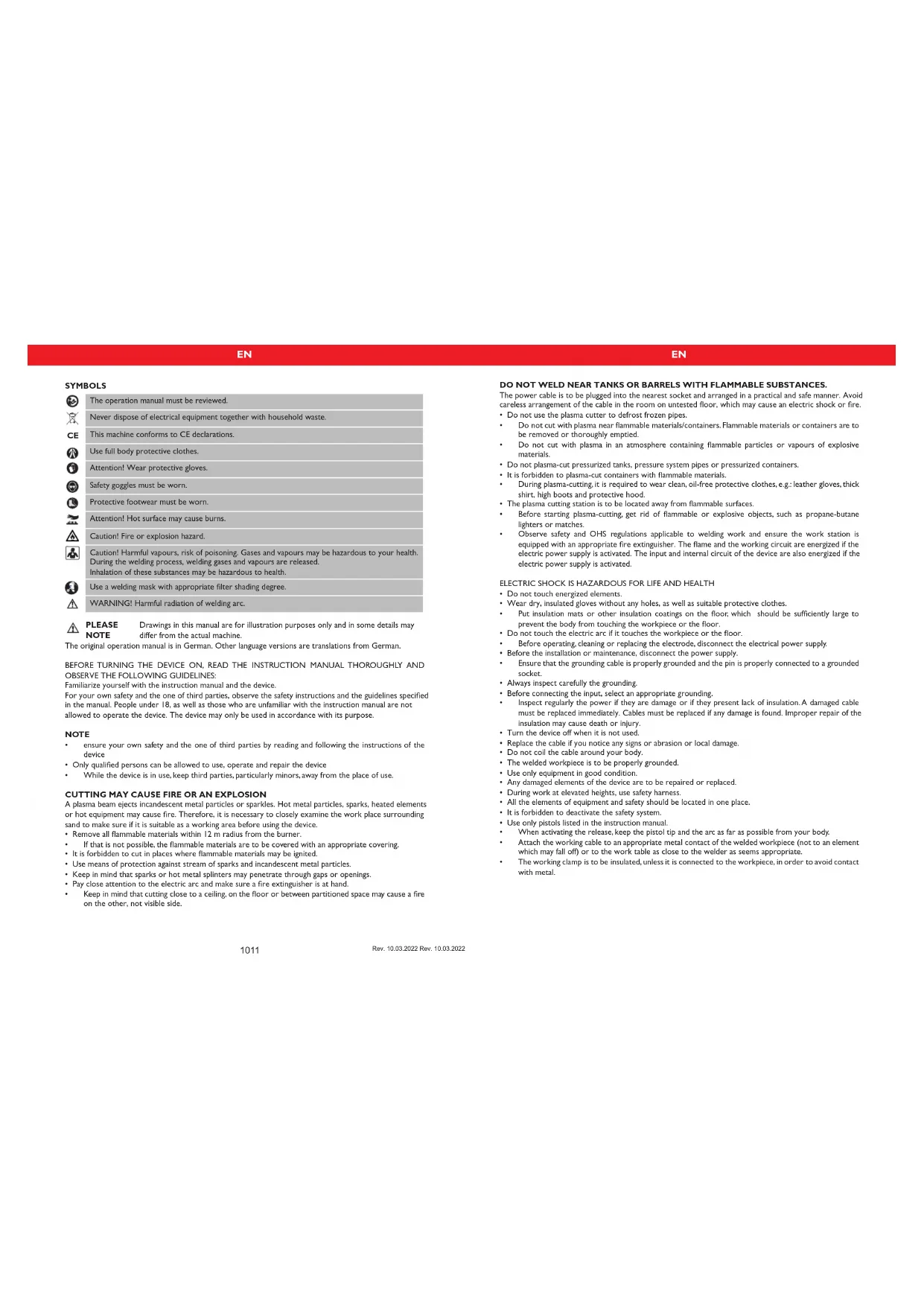
CONNECTION DIAGRAM S-PLASMA 40
I. supply connection
2workpiece
3. ground cable connector
4. plasma cutting clamp
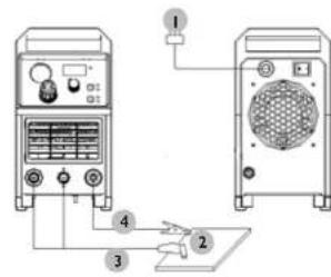
S-PLASMA 40
I. ON/OFF SWITCH
2 OVERLOAD / FAULT LED INDICATOR:
a) If the machine has malfunctioned and cannot be operated
b) If the cutting device has exceeded the standard working time the protection mode is initiated and the machine will stop functioning. This means that the machine is now being cooled in order to be able to restore temperature control again after the device has overheated. Therefore the machine is stopped. During this process, the red warning light on the front panel lights up. In this case it is not necessary to remove the power plug from the socket. The ventilation system may be left on in order to enhance the cooling of the machine. When the red light goes dark, this means that the temperature is now down to the normal level and the unit can be put back into operation.
- CUTING CURRENT ADJUSTING KNOB
- Gas Delay - Setting the time of the air flow after the cutting torch (2.5s or 5s)
- GROUNDING CABLE CONNECTION
- Power supply connection to the plasma torch cable.
GROUNDING:
- Compressed air connection to the plasma torch cable
EN
EN
TECHNICAL DETAILS
| Product name Plasma cutting machine | |
| Model S-PLASMA 40 | |
| Rated voltage 230V~ | |
| Frequency 50Hz | |
| Cooling Fan | |
| Cutting current 20 A - 40 A | |
| Rated operation cycle 60 % | |
| Safety class IP IP 21 | |
| Weight 22 kg | |
| Compressor | |
| Compressor type Oil-free | |
| Rated voltage 230V~ | |
| Frequency 50Hz | |
| Power | 750W |
Unpack all the items which are in the box and make sure that you have received all items which are listed on the packing list.
B.WORK ENVIRONMENT
Make sure that the work area is well ventilated. The unit is cooled by an axial fan that provides an air flow for the electronics through the rear panel.
(Note! The housing must be installed in order to ensure that the vent holes are closer to the front of the machine). Leave at least 15cm at the front and 15cm at both sides for cleaning. If the machine is operated without the adequate cooling, the length of the duty cycle will be greatly reduced.
C. CABLE CONNECTIONS
Each unit is equipped with a main power cable, which is responsible for providing current and voltage to the device. If the device is connected to power, which exceeds the required voltage, or if the wrong phase is set, it may lead to severe damage to the unit. This is not covered by the warranty for the equipment and the user will be responsible for such situations.
D. TORCH CONNECTIONS
Connect the torch to the inverter by connecting the air tube that is attached at the end of the torch to the torch connector on the front part of the machine. Ensure that the connection is secure by tightening it slightly with a spanner. However you should not make it too tight.
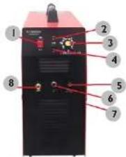
PISTOL ASSEMBLY
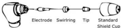
A.ASSEMBLING THE PISTOL
Put the pistol the protective cap facing up and turn the cap away from the gun. (The protective cap holds the tip, the ceramic swirl ring and the electrode together). Remove the cap, the ceramic swirl ring and the electrode. Assemble the electrode, the ceramic swirl ring and the tip back together. Replace worn parts if necessary. Put the protective cap on the head of the pistol and screw it on with your hand until it is snug. If any resistance is present during this process, check the thread and the arrangement of the items before resuming work.
NOTE
In case of some pistols with no reversible electrodes it is necessary to tighten the electrode further by using a pair of pliers in order to ensure a reliable electrical connection.
INSTRUCTION FOR USE
A. THE BEGINNING
Turn the power switch to "ON". Press the pistol switch (air will flow out from the pistol).
B.WEEKLY ACTIVITIES
Verify the proper operation of the air flow. Blow off or suck in dust or dirt from the entire machine, including the air filter.
MAINTENANCE
Check the pistol for wear damage, cracks or exposed wire sections. Replace or repair any such defects before using the device. A heavily worn pistol tip/nozzle contributes to the reduction of speed, voltage drops and crooked cuts. An indication of a worn pistol tip/nozzle is an elongated or oversized nozzle opening.
TRANSPORTATION AND STORAGE
Shaking, crashing and turning upside down of the device should be prevented when transporting it. Store it in a properly ventilated place with dry air and without any corrosive gas.
CLEANING AND MAINTENANCE
- Disconnect the device from the electricity when cleaning the equipment.
Use cleaner without corrosive substances to clean the surface.
Dry all parts well before the device is used again.
Store the unit in a dry, cool place, free from moisture and direct exposure to sunlight.
REGULAR CONTROL OF THE DEVICE
Check regularly whether the device is damaged. If it should be damaged, please stop using it immediately and contact your customer service to solve the problem.
What to do in case of a problem?
Please contact your customer service and prepare the following information:
If relevant, take a picture of the damaged, broken or defective part.
- It will be easier for your customer service clerk to determine the source of the problem if you give a detailed and precise description of the matter. The more detailed your information, the better the customer service will be able to solve your problem rapidly and efficiently!
CAUTION: Never open the device without the authorization of your customer service. This can lead to a loss of warranty!
STAMOS WELDING GROUP
INSTRUKCJA OBSLUGI
S-PLASMA 40
PL
SYMBOLE
Rev. 10.03.2022 Rev. 10.03.2022
PL
DANETECHNICZNE
NAMEPLATETRANSLATIONS
| expando de Serial No. Producao estar | Model S Puma 4G | ||||
| 1- | 2- | 3- | 4- | ||
| U | 20A/86V-40A/96V | ||||
| - - - | X | 60% | 100% | ||
| - | Uo=230V | I2 | 40A | 31A | |
| U2 | 96V | 92V | |||
| D=1-50Hz | U1=230V- | Imax:22.1A | Hatt:16.4A | ||
| IP21 | F | GAS | |||
| 20A/86V-40A/96V | ||||
| = = = | X | 60% | 100% | |
| Uo=230V | I2 | 40A | 31A | |
| U2 | 96V | 92V | ||
| U1=230V~ | Imax=22.1A | Ioff=16.4A | ||
| IP21 | F | GAS | ||
| response data Number and No. produced | Moist:5 N/cm 40 | ||||
| 1-14-10-11-12-13-14-15-16-17-18-19-20-21-22-23-24-25-26-27-28-29-30-31-32-33-34-35-36-37-38-39-40-41-42-43-44-45-46-47-48-49-50-51-52-53-54-55-56-57-58-59-60-61-62-63-64-65-66-67-68-69-70-71-72-73-74-75-76-77-78-79-80-81-82-83-84-85-86-87-88-89-90-91-92-93-94-95-96-97-98-99-100-101-102-103-104-105-106-107-108-109-110-111-112-113-114-115-116-117-118-119-120-121-122-123-124-125-126-127-128-129-130-131-132-133-134-135-136-137-138-139-140-141-142-143-144-145-146-147-148-149-150-151-152-153-154-155-156-157-158-159-160-161-162-163-164-165-166-167-168-169-170-171-172-173-174-175-176-177-178-179-180-181-182-183-184-185-186-187-188-189-190-191-192-193-194-195-196-197-198-199-200-201-202-203-204-205-206-207-208-209-210-211-212-213-214-215-216-217-218-219-220-221-222-223-224-225-226-227-228-229-230-231-232-233-234-235-236-237-238-239-240-241-242-243-244-245-246-247-248-249-250-251-252-253-254-255-256-257-258-259-260-261-262-263-264-265-266-267-268-269-270-271-272-273-274-275-276-277-278-279-280-281-282-283-284-285-286-287-288-289-290-291-292-293-294-295-296-297-298-299-300-301-302-303-304-305-306-307-308-309-310-311-312-313-314-315-316-317-318-319-320-321-322-323-324-325-326-327-328-329-330-331-332-333-334-335-336-337-338-339-340-341-342-343-344-345-346-347-348-349-350-351-352-353-354-355-356-357-358-359-360-361-362-363-364-365-366-367-368-369-370-371-372-373-374-375-376-377-378-379-380-381-382-383-384-385-386-387-388-389-390-391-392-393-394-395-396-397-398-399-400-401-402-403-404-405-406-407-408-409-410-411-412-413-414-415-416-417-418-419-420-421-422-423-424-425-426-427-428-429-430-431-432-433-434-435-436-437-438-439-440-441-442-443-444-445-446-447-448-449-450-451-452-453-454-455-456-457-458-459-460-461-462-463-464-465-466-467-468-469-470-471-472-473-474-475-476-477-478-479-480-481-482-483-484-485-486-487-488-489-490-491-492-493-494-495-496-497-498-499-500-501-502-503-504-505-506-507-508-509-510-511-512-513-514-515-516-517-518-519-520-521-522-523-524-525-526-527-528-529-530-531-532-533-534-535-536-537-538-539-540-541-542-543-544-545-546-547-548-549-550-551-552-553-554-555-556-557-558-559-560-561-562-563-564-565-566-567-568-569-570-571-572-573-574-575-576-577-578-579-580-581-582-583-584-585-586-587-588-589-590-591-592-593-594-595-596-597-598-599-600-601-602-603-604-605-606-607-608-609-610-611-612-613-614-615-616-617-618-619-620-621-622-623-624-625-626-627-628-629-630-631-632-633-634-635-636-637-638-639-640-641-642-643-644-645-646-647-648-649-650-651-652-653-654-655-656-657-658-659-660-661-662-663-664-665-666-667-668-669-670-671-672-673-674-675-676-677-678-679-680-681-682-683-684-685-686-687-688-689-690-691-692-693-694-695-696-697-698-699-700-701-702-703-704-705-706-707-708-709-710-711-712-713-714-715-716-717-718-719-720-721-722-723-724-725-726-727-728-729-730-731-732-733-734-735-736-737-738-739-740-741-742-743-744-745-746-747-748-749-750-751-752-753-754-755-756-757-758-759-760-761-762-763-764-765-766-767-768-769-770-771-772-773-774-775-776-777-778-779-780-781-782-783-784-785-786-787-788-789-790-791-792-793-794-795-796-797-798-799-800-801-802-803-804-805-806-807-808-809-810-811-812-813-814-815-816-817-818-819-820-821-822-823-824-825-826-827-828-829-830-831-832-833-834-835-836-837-838-839-840-841-842-843-844-845-846-847-848-849-850-851-852-853-854-855-856-857-858-859-860-861-862-863-864-865-866-867-868-869-870-871-872-873-874-875-876-877-878-879-880-881-882-883-884-885-886-887-888-889-890-891-892-893-894-895-896-897-898-899-900-901-902-903-904-905-906-907-908-909-910-911-912-913-914-915-916-917-918-919-920-921-922-923-924-925-926-927-928-929-930-931-932-933-934-935-936-937-938-939-940-941-942-943-944-945-946-947-948-949-950-951-952-953-954-955-956-957-958-959-960-961-962-963-964-965-966-967-968-969-970-971-972-973-974-975-976-977-978-979-980-981-982-983-984-985-986-987-988-989-990-991-992-993-994-995-996-997-998-999-1000- 1010 1011 1012 IP21 GAS ######## ######## ######## ######## ######## ######## ######## ######## ######## ######## ######## ######## ######## ######## ######## ######## ######## ######## ######## ######## ######## ######## ######## ######## ######## ######## ######## ######## ######## ######## ######## ######## ######## ######## ######## ######## ######## ######## ######## ######## ######## ######## ######## ######## ######## ######## ######## ######## ######## ######## ####### | |||||
NAMEPLATE TRANSLATIONS
| 20A/86V-40A/96V | ||||
| = - - = | X | 60% | 100% | |
| Uo=230V | I2 | 40A | 31A | |
| U2 | 96V | 92V | ||
| U1=230V- | Imax:22.1A | Heft=16.4A | ||
| IP21 | F | GAS | ||
| 20A/86V-40A/96V | ||||
| --- | X | 60% | 100% | |
| Uo=230V | I2 | 40A | 31A | |
| U2 | 96V | 92V | ||
| U1=230V~ | Imax 22.1A | Infe 16.4A | ||
| IP21 | F | GAS | ||
| expounds.com Nombre de solde Prix de production | Model: S-Pharma 4D | |||
| 1-2400-1-1= | ||||
| U | 20A/86V-40A/96V | |||
| —— | X | 60% | 100% | |
| — | Uo=230V | I2 | 40A | 31A |
| U2 | 96V | 92V | ||
| 1-50Hz | U1=230V | Imax:22.1A | Heft=16.4A | |
| IP21 | F | GAS | ||
NAMEPLATETRANSLATIONS
| expando com Scientific Endo Particular | Model S Ptera 4G | |||
| 1- | 2- | 3- | 4- | |
| U | 20A/86V-40A/96V | |||
| - - - | X | 60% | 100% | |
| - | U0=230V | I2 | 40A | 31A |
| U2 | 96V | 92V | ||
| D=1-50Hz | U1=230V- | Imax:22.1A | Hatt:16.4A | |
| IP21 | F | GAS | ||
NOTIZEN | NOTES NOTIZEN | NOTES
For the disposal of the device please consider and act according to the national and local rules and regulations.
CONTACT
expondo Polska sp. z o.o. sp. k.