
700 - Drill RIDGID - Free user manual and instructions
Find the device manual for free 700 RIDGID in PDF.
| Product Type | Electric Pipe Threading Drive System |
| Brand | Ridgid |
| Model | 700 |
| Threading Capacity (Pipe) | 1/8" to 2" (3 to 50 mm) |
| Threading Capacity (Bolts) | 1/4" to 1" (6 to 25 mm) with 00-RB die head |
| Motor Type | Universal, reversible |
| Supply Voltage | 110-120 V / 220-240 V |
| Current Draw | 13.5 A (110-120 V) / 6.5 A (220-240 V) |
| Frequency | 50/60 Hz |
| Power | 1500 W |
| No-load Speed | 26 to 30 RPM |
| Control | Toggle switch/reversing switch with automatic stop return |
| Gear Housing | Aluminum casting, with reduction gear, spring-loaded pawls, and hardened steel spindle |
| Dimensions (L × W × H) | 717 × 154 × 198 mm |
| Approximate Weight | Approximately 10 kg (estimated) |
| Standard Equipment | Drive system, stand, torque arm, instruction manual |
| Compatible Accessories | Die heads 12-R, 00-R, 11-R, adapters 770-774, support arm 775, pipe cutter 258 |
| Cleaning and Maintenance | Clean after each use; lubricate gear housing every 3 to 6 months; replace brushes if < 6 mm |
| Safety | Safety glasses mandatory; do not wear gloves or loose clothing; use support device for pipes ≥ 1" |
| Warranty | Full Lifetime Warranty against defects in materials and workmanship |
Frequently Asked Questions - 700 RIDGID
User questions about 700 RIDGID
0 question about this device. Answer the ones you know or ask your own.
Ask a new question about this device
Download the instructions for your Drill in PDF format for free! Find your manual 700 - RIDGID and take your electronic device back in hand. On this page are published all the documents necessary for the use of your device. 700 by RIDGID.
USER MANUAL 700 RIDGID
natural_image
Rigid digester tool with red markings and a blue cable, no visible text or symbols on the device itself.Table of Contents
Recording Form For Machine Serial Number....1
Safety Symbols 2
General Power Tool Safety Warnings
Work Area Safety 2
Electrical Safety 2
Personal Safety 3
Power Tool Use And Care ....3
Service ....3
Specific Safety Information
Power Drive Safety Warnings ....3
Description, Specifications And Standard Equipment
Description 4
Specifications 4
Standard Equipment 5
Pre-Operation Inspection
Set-Up and Operation....6
Installing Die Heads 6
Resisting Threading Forces 7
Threading....8
Inspecting Threads....9
700 Power Drive – Other Uses
Maintenance Instructions
Cleaning....10
Lubrication 10
Changing Dies in 12-R Die Heads ....10
Replacing Brushes in Motor 10
Optional Equipment
Machine Storage 11
Service And Repair
Thread Cutting Oil Information 11
Disposal 11
Troubleshooting 12
EC Declaration of Conformity....Inside Back Cover
Lifetime Warranty ....Back Cover
*Original Instructions - English
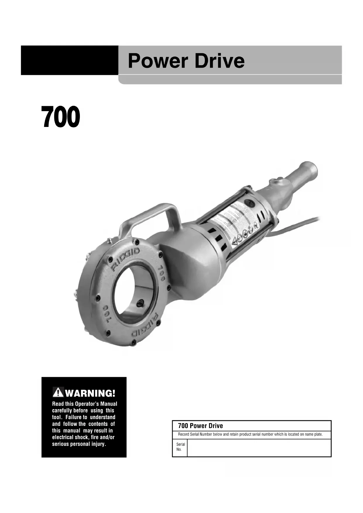
Power Drive
700
natural_image
Rigid digester tool with attached circular base and handle, no visible text or symbols on body
WARNING!
Read this Operator's Manual carefully before using this tool. Failure to understand and follow the contents of this manual may result in electrical shock, fire and/or serious personal injury.
| 700 Power Drive | |
| Record Serial Number below and retain product serial number which is located on name plate. | |
| Serial No. | |
Safety Symbols
In this operator's manual and on the product, safety symbols and signal words are used to communicate important safety information. This section is provided to improve understanding of these signal words and symbols.

This is the safety alert symbol. It is used to alert you to potential personal injury hazards. Obey all safety messages that follow this symbol to avoid possible injury or death.

DANGER
DANGER indicates a hazardous situation which, if not avoided, will result in death or serious injury.

WARNING
WARNING indicates a hazardous situation which, if not avoided, could result in death or serious injury.

CAUTION
CAUTION indicates a hazardous situation which, if not avoided, could result in minor or moderate injury.
NOTICE
NOTICE indicates information that relates to the protection of property.

This symbol means read the operator's manual carefully before using the equipment. The operator's manual contains important information on the safe and proper operation of the equipment.

This symbol means always wear safety glasses with side shields or goggles when handling or using this equipment to reduce the risk of eye injury.

This symbol indicates the risk of fingers, hands, clothes and other objects catching on or between gears or other rotating parts and causing crushing injuries.

This symbol indicates the risk of electrical shock.

This symbol indicates the risk of machine tipping, causing striking or crushing injuries.

This symbol means do not wear gloves while operating this machine to reduce the risk of entanglement.

This symbol means always use support device to help resist threading force, improve control and reduce the risk of injury.
General Power Tool Safety Warnings\*
WARNING
Read and understand all instructions. Failure to follow all instructions listed below may result in electric shock, fire, and/or serious injury.
SAVE ALL WARNINGS AND INSTRUCTIONS FOR FUTURE REFERENCE!
The term "power tool" in the warnings refers to your mains-operated (corded) power tool or battery-operated (cordless) power tool.
Work Area Safety
- Keep work area clean and well lit. Cluttered or dark areas invite accidents.
- Do not operate power tools in explosive atmospheres, such as in the presence of flammable liquids, gases, or dust. Power tools create sparks which may ignite the dust or fumes.
- Keep children and by-standers away while operating a power tool. Distractions can cause you to lose control.
Electrical Safety
- Power tool plugs must match the outlet. Never mod ify the plug in any way. Do not use any adapter plugs with earthed (grounded) power tools. Grounded tools must be plugged into an outlet properly installed and grounded in accordance with all codes and ordinances. Never remove the grounding prong or modify the plug in any way. Check with a qualified electrician if you are in doubt as to whether the outlet is properly grounded. Unmodi fied plugs and matching outlets will reduce risk of electric shock.
- Avoid body contact with earthed or grounded surfaces such as pipes, radiators, ranges and refrigerators. There is an increased risk of electrical shock if your body is earthed or grounded.
- Do not expose power tools to rain or wet conditions. Water entering a power tool will increase the risk of electrical shock.
-
Do not abuse the cord. Never use the cord to carry the tool or pull the plug from an outlet. Keep cord away from heat, oil, sharp edges or moving parts. Replace damaged cords immediately. Damaged cords increase the risk of electric shock.
-
When operating a power tool outside, use an outdoor extension cord marked "W-A" or "W". These cords are rated for outdoor use and reduce the risk of electric shock.
- If operating a power tool in a damp location is unavoidable, use a ground fault circuit interrupter (GFCI) protected supply. Use of a GFCI reduces the risk of electric shock.
- Australia: If operating a power tool in a damp location is unavoidable, use a Residual Current Device (RCD) protected supply. Use of a RCD reduces the risk of electric shock.
• Australia: It is recommended that the tool always be supplied via a Residual Current Device having a residual current of 30mA or less.
Personal Safety
- Stay alert, watch what you are doing and use common sense when operating a power tool. Do not use a power tool while you are tired or under the influence of drugs, alcohol, or medication. A moment of inattention while operating power tools may result in serious personal injury.
- Use personal protective equipment. Always wear eye protection. Protective equipment such as dust mask, non-skid safety shoes, hard hat, or hearing protection used for appropriate conditions will reduce personal injuries.
- Prevent unintentional starting. Ensure the switch is in the OFF position before connecting to power source and/or battery pack, picking up or carrying the tool. Carrying power tools with your finger on the switch or energizing power tools that have the switch ON invites accidents.
- Remove any adjusting key or wrench before turning the power tool ON. A wrench or a key left attached to a rotating part of the power tool may result in personal injury.
- Do not overreach. Keep proper footing and balance at all times. This enables better control of the power tool in unexpected situations.
- Dress properly. Do not wear loose clothing or jewelry. Keep your hair, and clothing away from moving parts. Loose clothes, jewelry, or long hair can be caught in moving parts.
- If devices are provided for the connection of dust extraction and collection facilities, ensure these are connected and properly used. Use of dust collection can reduce dust-related hazards.
Power Tool Use and Care
- Do not force power tool. Use the correct power tool for your application. The correct power tool will do the job better and safer at the rate for which it is designed.
- Do not use power tool if the switch does not turn it ON and OFF. Any power tool that cannot be controlled with the switch is dangerous and must be repaired.
- Disconnect the plug from the power source and/or the battery pack from the power tool before making any adjustments, changing accessories, or storing power tools. Such preventive safety measures reduce the risk of starting the power tool accidentally.
- Store idle power tools out of the reach of children and do not allow persons unfamiliar with the power tool or these instructions to operate the tool. Power tools are dangerous in the hands of untrained users.
- Maintain power tools. Check for misalignment or binding of moving parts, breakage of parts and any other condition that may affect the power tool's operation. If damaged, have the power tool repaired before use. Many accidents are caused by poorly maintained power tools.
- Keep cutting tools sharp and clean. Properly maintained cutting tools with sharp cutting edges are less likely to bind and are easier to control.
- Use the power tool, accessories and tool bits etc. in accordance with these instructions, taking into account the working conditions and the work to be performed. The use of the power tool for operations different from those intended could result in a hazardous situation.
Service
- Have your power tool serviced by a qualified repair person using only identical replacement parts. This will ensure that the safety of the power tool is maintained.
Specific Safety Information
WARNING
This section contains important safety information that is specific to this tool.
Read these precautions carefully before using the 700 Power Drive to reduce the risk of electrical shock, striking, crushing or other serious injury.
SAVE ALL WARNINGS AND INSTRUCTIONS FOR FUTURE REFERENCE!
Keep this manual with machine for use by the operator.
Power Drive Safety
- Follow instructions on proper use of this machine. Read and understand the instructions and warnings for all equipment and material being used before operating the power drive. Failure to follow all warnings and instructions may result in property damage and/or serious injury.
- When threading 1" (25mm) or larger pipe, use sup port device to resist threading forces. Use an appropriate support device per these instructions. Support devices improve control and reduce the risk of striking, crushing, and/or other injuries.
- When using a support device other than the support arm, the support device must react against the motor housing. Support devices contacting other parts may damage the machine parts or increase the risk of injury.
- Always firmly hold the power drive when threading or backing die head off the pipe to resist threading forces, regardless of support device use. This will reduce the risk of striking, crushing and other injuries.
- Do not use this power drive if switch button is broken. This switch is a safety device that lets you shut off the motor by releasing the switch.
- Do not wear gloves or loose clothing when operating machines. Keep sleeves and jackets buttoned. Do not reach across the machine or pipe. Clothing can be caught by the pipe or machine resulting in entanglement.
- One person must control the work process and machine operation. Only the operator should be in the work area when the machine is running. This helps reduce the risk of injury.
- Do not use dull or damaged dies. Sharp cutting tools require less torque and the power drive is easier to control.
- Keep handles dry and clean, free from oil and grease. Allows for better control of tool..
- Keep floors dry and free of slippery materials such as oil. Slippery floors invite accidents.
- Only use RIDGID die heads with RIDGID 700 Power Drive, other die heads may not fit correctly in the power drive increasing the risk of equipment damage and personal injury.
- When using for applications other than described in this manual, use a support device to resist handle forces. Support devices improve control and reduce the risk of striking, crushing, and/or other injuries.
If you have any question concerning this RIDG Product:
- Contact your local RIDGID® distributor.
- Visit RIDGID.com to find your local RIDGID contact point.
- Contact Ridge Tool Technical Service Department at rttechservices@emerson.com, or in the U.S. and Cana da call (800) 519-3456.
Description, Specifications And Standard Equipment Description
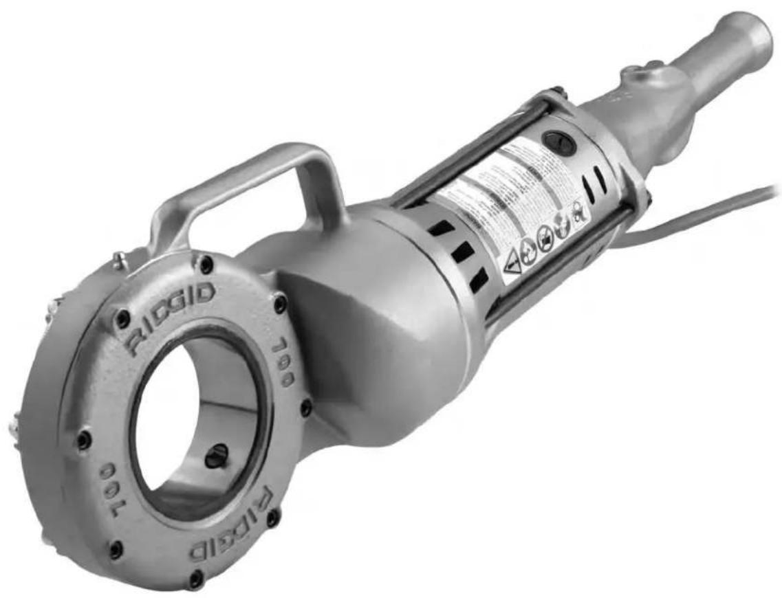
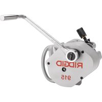
The RIDGID® Model 700 Power Drive is designed to provide power for threading pipe and conduit. Forward and Reverse rotation can be selected with a reversible switch.
The power drive is designed to use RIDGID 12-R Die Heads (1/8" - 2" pipe). Other RIDGID die heads such as the OO-R and 11-R can be used with adapters.
When threading 1" or larger pipe, a support device, such as the No. 775 Support Arm or a RIDGID 14" heavy duty pipe wrench is required to resist the threading forces.
The power drive can also be used to power the RIDGID 258 Pipe Cutter and for other applications, (See "Other Uses").
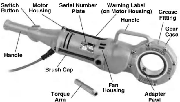
Figure 1 – Model 700 Power Drive
Specifications
Threading Capacity ....Pipe 18 " to 2" (3 to 50 mm) Bolt 14 " to 1" (6 to 25 mm) with 00-RB Die Head
Motor*:
Type ....Universal, Reversible
Volts ....110 120 220-240
Amps ....13.5 13.5 6.5
Frequency ....50/60 Hz 50/60 Hz 50/60 Hz
Power ....1500 1500 1500
Operating Speed.....26-30 RPM, No load
Controls......Double-Throw Reversible Switch with spring return to OFF position
Gear Head ....Die Cast Aluminum, Spur Gear Reduction Face Gear Drive, Spring-Loaded Adapter Pawls, Hardened Steel Spindle Gear
Dimension:
Length.....28 ^1/4 " (717 mm)
Width....6 ^1/16 " (154 mm)
Height....7 ^13 / _16 " (198 mm)
Weight ......25 lbs. (11 kg)
Sound Pressure ( 12 )**.....98.4 dB(A), K=3
Sound Power (I _A )** .....107 dB(A), K=3
Vibration ^** ......2.5 m/s ^2 , K=1.5
* Refer to your machine serial number plate for motor information for your specific machine – Other versions are available.
** Sound and vibration measurements are measured in accordance with a standardized test per Standard EN 62481-1.
- Vibration levels may be used for comparison with other tools and for preliminary assessment of exposure.
- Sound and vibration emissions may vary due to your location and specific use of these tools.
- Daily exposure levels for sound and vibration need to be evaluated for each application and appropriate safety measures taken when needed. Evaluation of exposure levels should consider the time a tool is switched off and not in use. This may significantly reduce the exposure level over the total working period.
Standard Equipment
The Model 700 Power Drive comes with the following items:
- 700 Power Drive • Torque arm
- Support Device • Operator's Manual
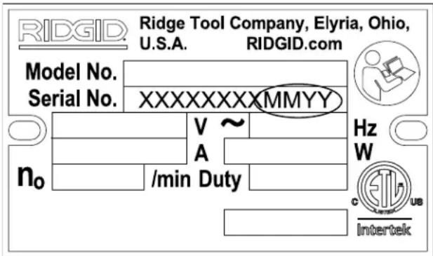
Figure 2 – Machine Serial Number
The 700 Power Drive machine serial number plate is located on the bottom of motor housing. The last 4 digits indicate the month and year of the manufacture. (MM = month, YY = year).
NOTICE Selection of appropriate materials and installation, joining and forming methods is the responsibility of the system designer and/or installer. Selection of improper materials and methods could cause system failure.
Stainless steel and other corrosion resistant materials can be contaminated during installation, joining and forming. This contamination could cause corrosion and pre-
mature failure. Careful evaluation of materials and methods for the specific service conditions, including chemical and temperature, should be completed before any installation is attempted.
Pre-Operation Inspection
WARNING


Before each use, inspect your 700 Power Drive and correct any problems to reduce the risk of serious injury from electric shock, crushing injuries and
other causes and prevent power drive damage.
- Make sure that the power drive is unplugged.
- Clean any oil, grease or dirt from the power drive and support device, including the handles and controls. This aids inspection and helps prevent the machine or control from slipping from your grip.
-
Inspect the power drive for the following:
-
Damage or modification to the cord and plug.
- Proper assembly, maintenance and completeness.
- Damaged, misaligned or binding parts.
- Proper operation of switch. Confirm that it cycles smoothly and does not stick.
- Presence and readability of warning labels (Figure 3).
- Any other condition which may prevent safe and normal operation.
If any problems are found, do not use the power drive or support device until the problems have been repaired.
- Inspect support arm. Make sure gripping teeth are clean and in good condition. Teeth can be cleaned with a wire brush.
- Inspect the cutting edges of the dies for wear, deformation, chips or other issues. Dull or damaged cutting tools increase the amount of force required, produce poor quality threads and increase the risk of injury.
- Inspect and maintain any other equipment being used per its instructions to make it is sure functioning properly.
- Following the Set-Up and Operation instructions, check the power drive for proper operation.
- Depress and release the switch for FORWARD rotation and repeat for REVERSE rotation as shown in Figure 3. Confirm that the power drive rotates as shown in Figure 3 and that the switch controls the machine operation.
Allow the power drive to come to a complete stop before reversing the direction with the switch button. This will reduce the risk of power drive damage.
- Depress and hold the switch button. Inspect the moving parts for misalignment, binding, odd noises or any other unusual conditions. Release the switch.
If the machine does not operate correctly or any unusual conditions are found, do not use the machine until it has been repaired.
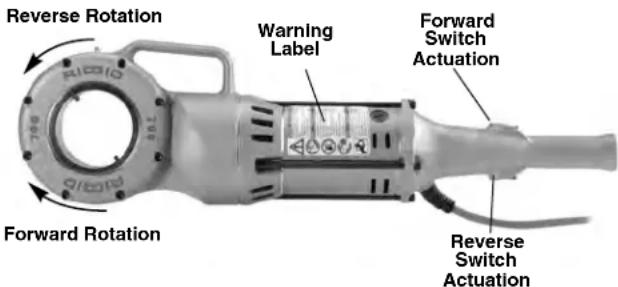
Figure 3 – Switch Position for Rotational Direction
- Release the switch button and with dry hands unplug the machine.
Set-Up and Operation
WARNING


Set up and operate the 700 Power Drive according to these procedures to reduce the risk of injury from electric shock, entanglement, striking, crushing and other causes, and to help prevent power drive damage.
When threading 1" (25mm) or larger pipe, use support device to resist threading forces. Use an appropriate support device per these instructions. Support devices improve control and reduce the risk of striking, crushing, and/or other injuries.
Always firmly hold the power drive when threading or backing die head off the pipe to resist threading forces, regardless of support device use. This will reduce the risk of striking, crushing and other injuries.
Properly support pipe. This will reduce the risk of falling pipe, tipping and serious injury.
Do not use a power drive without a properly operating switch button.
Do not wear gloves or loose clothing when operating machines. Keep sleeves and jackets buttoned. Do not reach across the machine or pipe. Clothing can be caught by the pipe or machine resulting in entanglement.
One person must control both the work process and the switch button. Do not operate with more than one person. In case of entanglement, the operator must be in control of the switch.
-
Check work area for:
-
Adequate lighting.
- Flammable liquids, vapors or dust that may ignite. If present, do not work in area until sources have been identified and corrected. The power drives are not explosion proof and can cause sparks.
- Clear, level, stable, dry location for all equipment and operator.
- Good ventilation. Do not use extensively in small, enclosed areas.
- Properly wired electrical outlet of the correct voltage. If in doubt, have outlet inspected by a licensed electrician.
-
Clear path to electrical outlet that does not contain any potential sources of damage for the power cord.
-
Inspect the pipe to be threaded and associated fittings and confirm that the 700 Power Drive is a correct tool for the job. See Specifications.
Equipment for other applications can be found in the Ridge Tool catalog, online at RIDGID.com or by calling Ridge Tool Technical Service in the U.S. and Canada at (800) 519-3456
- Make sure equipment to be used has been properly inspected.
- Properly prepare the pipe as needed. Make sure the pipe is squarely cut and deburred. Pipe cut at an angle can damage the dies while threading or cause difficulty engaging the die head.
- Make sure that pipe to be threaded is stable and secured to prevent tipping during use. Use appropriate pipe stands to support pipe length.
- Check the level of RIDGID Thread Cutting Oil in the RIDGID 418 oiler. Remove the chip tray and confirm that the filter screen is clean and fully submerged in oil. Replace or add oil if necessary. Place the 418 Oiler bucket under the pipe end to be threaded.
Installing Die Heads
- Make sure the power drive is unplugged from the outlet.
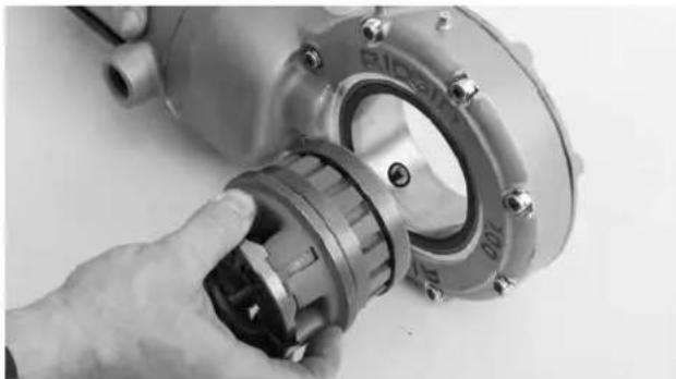
- Push 12-R Die Head or Adapter (see Optional Equipment), spline end first, squarely into the Power Drive until the spring-loaded drive pawls securely engage
the spline. (Figure 4). The die head or adapter can be inserted into either side of the power drive. In some cases, die heads/adapters may need to be rotated to allow the pawl to engage. 770 and 773 adapters must have the die head installed in the adapter prior to insertion in the Power Drive.
- To remove, squarely pull die head from power drive. If needed, use a soft face hammer or a block of wood to tap the die head out. Do not pound on the die head, this can damage the tool.
natural_image
Close-up of a hand adjusting a mechanical component with a circular housing and bolted joints (no visible text or symbols)Figure 4 – Installing Die Heads into 700 Power Drive
Resisting Threading Forces (Support Devices)
For right hand threads, die head will rotate clockwise (looking at the face of the Die Head). Forces developed by the threading torque will be in the opposite or counter-clockwise direction. Rotation and force will be reversed for left hand threads. Make sure that the support device is set up to absorb and resist the threading force.
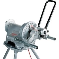
Using the No. 775 Support Arm:
- Support arm yoke hook can be assembled to either side. Securely tighten hinge bolt.
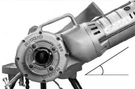
- Position the support arm on pipe so end of support arm aligns with end of pipe and 700 Power Drive will be slightly above horizontal (Figure 5 and 6). This properly places the support arm for threading and prevents threading oil from running down power drive.
- Make sure that the support arm jaws are squarely aligned with the pipe and securely tighten the support arm.
natural_image
Close-up of a mechanical clamp and bracket assembly (no visible text or symbols)Figure 5 – Support Arm Aligned with End of Pipe
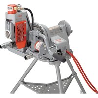
natural_image
Close-up of a LiDQI electric motor with visible cooling fins and mounting base (no text or symbols)Figure 6 – Support Arm Positioned With 700 Power Drive Slightly Above Horizontal
Using a RIDGID 12", 14" or 18" Heavy Duty Pipe Wrench:
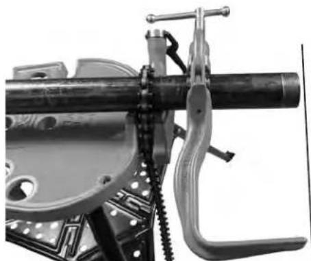
- Securely install the torque arm into the fan housing of the 700 Power Drive. A 5" (127 mm) long piece of 12 " schedule 80 steel pipe with a 12 " NPT thread can also be used.
- Place the RIDGID 12", 14" or 18" Heavy Duty Pipe Wrench approximately 7" (175 mm) from the end of the pipe (see Figure 7). Test to confirm the wrench is secure, and will not fall or move.
- When starting the thread, the torque arm will sit on the pipe wrench handle.
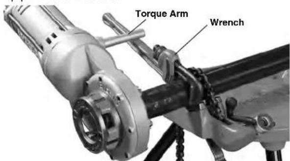
Figure 7 – Threading Using Pipe Wrench as a Support Arm
Other Support Methods:
Place the power drive motor housing (see Figure 1) a gainst an adjacent structural member (examples include walls, beams and joists). This requires that the pipe being threaded and surroundings are able to withstand the weight of the tool and the threading forces. It may be necessary to add temporary or permanent pipe supports or structural elements to properly resist threading forces.
For pipe 3 14 diameter and smaller:
Pipe 34 " and smaller nominal dimension can be threaded without the use of support device. In this case, the operator resists the threading forces. The pipe must be properly secured to prevent rotation. Always firmly hold the power drive when threading or backing die head off pipe to resist forces. This will reduce the risk of striking, crushing and other injuries.
Threading
- With dry hands, plug in the power drive.
- Position the die head over the pipe end and support the power drive as directed in the Resisting Threading Forces Section. Always keep the power drive against the support device. Do not put anything between the power drive and the support device – this increases the risk of pinching and crushing injuries.
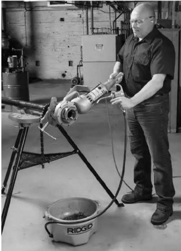
- Assume a proper operating position to help maintain control of the machine (See Figure 9),
- Be sure you have good balance and do not have to overreach.
- Be sure you can control the switch button and machine. Do not depress switch yet. In case of emergency you must be able to release switch.
natural_image
Close-up of a hand adjusting a car brake caliper on a vehicle chassis (no visible text or symbols)Figure 8 – Starting the Thread
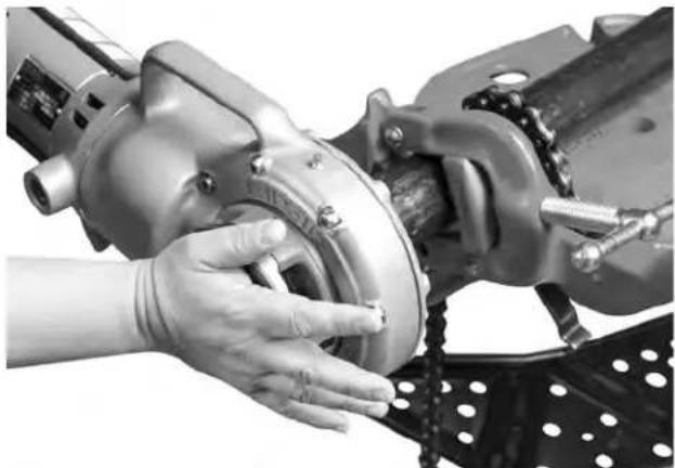
- Simultaneously actuate the switch button (see Figure 3) and push against the die head cover plate with the
palm of free hand to start the thread (Figure 8). Do not wear gloves, jewelry or use a rag while pushing on the cover plate – this increases the risk of entanglement and injury. Once the dies engage the pipe, threads will be cut as the dies pull themselves onto the end of the pipe.
Always firmly hold the power drive handle to resist the handle forces. Support devices can slip and allow the power drive to move. The switch button can be released at any time to shut OFF the power drive.
natural_image
Man operating a ridged tool in a workshop, no visible text or symbols on the equipment or backgroundFigure 9 – Threading Pipe
- Stop pushing on cover plate and use oiler to apply a generous quantity of RIDGID Thread Cutting Oil to the area being threaded. This will lower threading torque, improve thread quality and increase die life.
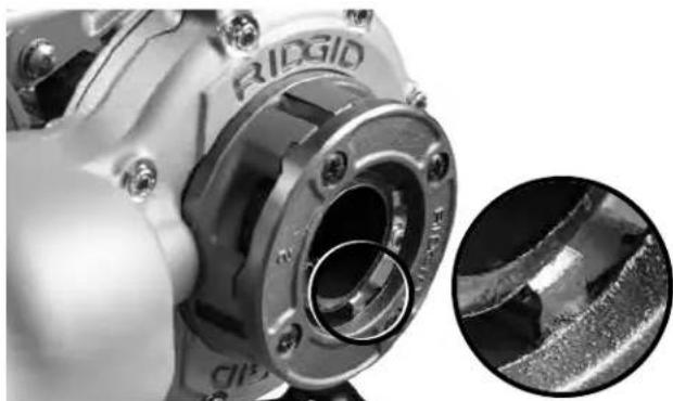
- Keep switch depressed until end of the pipe is even with edge of the dies (Figure 10). Watch to make sure Power Drive does not run into the support device. Release the switch button. Let the power drive come to a complete stop.
natural_image
Close-up of a mechanical component with a circular opening, showing internal features and a magnified inset (no text or symbols visible)Figure 10 – Pipe Even with Edge of Dies
- Actuate the switch button in reverse direction to remove die head from the threaded pipe. Hold onto the power drive handle firmly to resist the handle forces developed while breaking the thread chip and backing off the die head.
- Release the switch and remove the power drive and die head from the pipe.
- With dry hands, unplug the power drive.
- Wipe oil and debris off the threads and out of the die head, taking care not to cut yourself on sharp debris or edges. Clean up any oil spills in the work area.
Inspecting Threads
- Remove any oil, chips or debris from the thread.
- Visually inspect thread. Threads should be smooth and complete, with good form. If issues such as thread tearing, thin threads, or pipe out-of-roundness are observed, the thread may not seal when made up. Refer to the "Troubleshooting" chart for help in diagnosing these issues.
-
Inspect the size of the thread. The preferred method of checking thread size is with a ring gauge. There are various styles of ring gauges, and their usage may differ from that shown in Figure 11.
-
Screw ring gauge onto the thread hand tight.
- Look at how far the pipe end extends through the ring gage. The end of the pipe should be flush with the side of the gauge plus or minus one turn. If thread does not gauge properly, cut off the thread, adjust the die head and cut another thread. Using a thread that does not gauge properly can cause leaks.
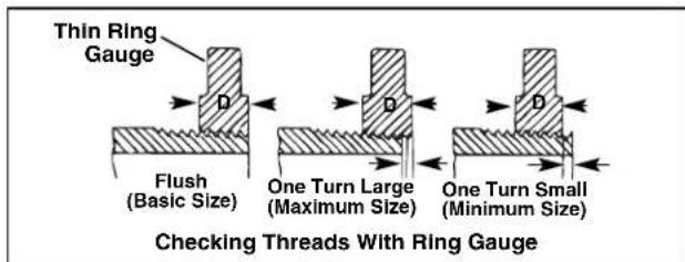
Figure 11 – Checking Thread Size
- If a ring gauge is not available to inspect thread size, it is possible to use a new clean fitting representative of those used on the job to gauge thread size. For 2" and under NPT threads, the threads should be cut to obtain 4 to 5 turns to hand tight engagement with the fitting and for 2" and under BSPT threads it should be 3 turns.
700 Power Drive - Other Uses
This manual contains specific instructions for the use of the 700 Power Drive to thread with various RIDGID die heads. When used with other RIDGID equipment (such as the RIDGID 258/258XL Power Pipe Cutter) follow the instructions and warnings supplied with that RIDGID equipment on proper set up and use.
Ridge Tool cannot provide specific instructions for every possible use for the 700 Power Drive. The user must evaluate the specific work scenario and use good work practices and methods. If there is any doubt about the use of the 700 Power Drive for these other purposes, do not use it.
If using the 700 Power Drive for other purposes, carefully evaluate and prepare for the work using the general guidelines below. The 700 Power Drive will supply high torque and correspondingly high handle forces which can cause striking and crushing injuries.
- The RIDGID 774 Square Drive Adapter can be used to adapt the 700 Power Drive to turn a male 15/16" square. Securely attach the adapter to prevent it from detaching in use.
- An appropriate method to withstand all handle forces must be developed (See "Resisting Handle Forces" section). Forces could exceed 1000 lbs (455 kg). Support devices can be placed against the motor housing or fan housing of the 700 Power Drive (Figure 1).
- Always keep the power drive against the support device – do not place body parts between the power drive and the support device.
- There should be no relative movement between the power drive and the support device during use.
- Confirm that the application (such as operating or exercising a valve) is free to turn, not jammed and that the ends of travel are known. If the system jams or goes solid during use, handle forces will increase abruptly and significantly or the power drive may rotate.
- If using to exercise or operate valves or other equipment, follow all equipment manufacturer instructions. Do not overload the equipment.
- Use such that the 700 Power Drive reaction force pulls away from the user.
- Release the switch button at any time to shut off the power drive. Make sure that you are able to release the switch button.
Maintenance Instructions
WARNING
Make sure that the switch button is released and the machine is unplugged before performing any maintenance or making any adjustments.
Maintain tool according to these procedures to reduce the risk of injury from electrical shock, entanglement and other causes.
Cleaning
-
After each use, empty the threading chips from the 418 Oiler chip tray and wipe out any oil residue.
-
Wipe off any oil, grease, chips or dirt from the power drive, including the handles and controls.
-
Wipe off any oil, grease or dirt from the support arm. If required, clean the support arm jaws with a wire brush.
-
Remove chips and dirt from die heads.
Lubrication
Use grease gun to add a Lithium EP (Extreme Pressure) grease through the grease fittings provided on the gear housing (see Figure 1) every 3 to 6 months, depending on usage of machine.
Changing Dies in 12-R Die Heads
A variety of dies are available for installation in RIDGID 12-R Die Heads. See catalog for availability.
-
Remove the four screws (4), cover plate (2) and dies (3) from die head.
-
Insert new dies into slots, numbered edge (1,2,3,4) up. Numbers on the dies must correspond with those on the die head slots. Always replace dies as a set.
-
Install the cover plate (2) and screws (4) and lightly tighten the screws.
- Screw a threaded pipe end into the dies until they begin to thread. This forces stop on dies "B" outward against lug "A" on cover plate and properly sets the size.
- Tighten the four screws securely. Remove the threaded pipe and make a test cut.
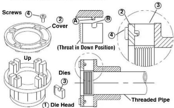
Figure 12 – Installing Dies in Die Head
Replacing Brushes in Motor
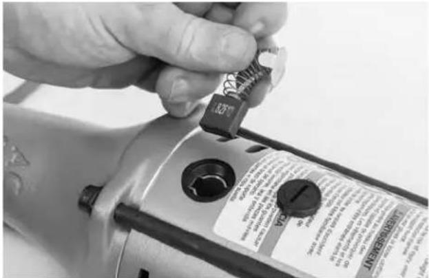
Check motor brushes every 6 months. Replace when worn to less than 14 " (6 mm).
natural_image
Close-up of a hand using a power tool to adjust a small component, no visible text or symbols on the device itself.Figure 13 – Brush Installation
- Unplug the machine from power source.
- Unscrew brush caps. Remove and inspect brushes. Replace when worn to less than 14 " (6 mm). Inspect the commutator for wear. If excessively worn, have tool serviced.
- Re-install brushes/install new brushes.
- Run the unit at idle for 15 minutes in the forward direction followed by 15 minutes in the reverse direction to seat new brushes to the commutator before use.
Optional Equipment
WARNING
To reduce the risk of serious injury, only use equipment specifically designed and recommended for use with the 700 Power Drive such as those listed below.
| CatalogNo. Description |
| 42600 770 Adapter for 00-R (1/8" - 1") and 00-RB (1/4" - 1") |
| 42605 771 Adapter for 0-R (1/8" - 1") |
| 42610 772 Adapter for 11-R (1/8" - 1 14 ") |
| 42615 773 Adapter for 111-R (1/8" - 1 14 ") |
| 42620 774 Square Drive Adapter -15/16 " |
| 42625 775 Support Arm |
| 46615 Torque Arm |
| 42950 B-1 71-X Metal Carrying Case |
| 10883 418 Oiler w/1 Gallon of Premium Thread Cutting Oil |
| 41620 Gearhead Motor Grease |
Further information on equipment available for 700 Power Drive specific to the tool can be found in the RIDGID Catalog and online at RIDGID.com.
Machine Storage
⚠ WARNING The 700 Power Drive must be kept indoors or well covered in rainy weather. Store the machine in a locked area that is out of reach of children and people unfamiliar with the machines. This machine can cause serious injury in the hands of untrained users.
Service And Repair
WARNING
Improper service or repair can make machine unsafe to operate.
The Maintenance Instructions will take care of most of the service needs of this machine. Any problems not addressed by this section should only be handled by an authorized RIDGID service technician.
Tool should be taken to a RIDGID Independent Service Center or returned to the factory. Use only RIDGID service parts.
For information on your nearest RIDGID Independent Service Center or any service or repair questions:
- Contact your local RIDGID distributor.
- Visit RIDGID.com to find your local RIDGID contact point.
- Contact Ridge Tool Technical Service Department at rttechservices@emerson.com, or in the U.S. and Canada call (800) 519-3456.
Thread Cutting Oil Information
Read and follow all instructions on the threading oil label and Safety Data Sheet (SDS). Specific information about RIDGID Thread Cutting Oils, including Hazard Identi fi ca tion, First Aid, Fire Fighting, Accidental Release Measures, Handling and Storage, Per sonal Protective Equipment, Disposal and Transportation, is included on the container and SDS. SDS is available at RIDGID.com or by contacting Ridge Tool Technical Service Department at (800) 519-3456 in U.S. and Canada or rttechservices@emerson.com.
Disposal
Parts of the 700 Power Drive contain valuable materials and can be recycled. There are companies that specialize in recycling that may be found locally. Dispose of the components in compliance with all applicable regulations. Contact your local waste management authority for more information.
For EC Countries: Do not dispose of electrical equipment with household waste!
According to the European Guideline 2012/ - 19/EU for Waste Electrical and Electronic Equipment and its implementation into national legislation, electrical equipment that is no
longer usable must be collected separately and disposed of in an environmentally correct manner.
Troubleshooting
| PROBLEM POSSIBLE REASONS SOLUTION | ||
| Machine will not run. | Brushes do not touch armature. | Check brushes, replace if worn. |
| Machine not able to thread. | Dull dies. | Replace dies. |
| Overload due to torn or out-of-round threads. | See possible reasons below. | |
| Poor quality or insufficient thread cutting oil. | Use RIDGID thread cutting oil in adequate quantity. | |
| Insufficient line voltage. | Check power supply voltage. | |
| Sparks forming at motor commutator | Insufficient contact between brushes and commutator | Tighten the brush caps to make sure brushes are pressed firmly onto commutator. |
| Brushes do not touch commutator properly. | Replace worn brushes and or armature. | |
| Brushes of different manufacture. | Only use RIDGID brushes. | |
| New brushes. | Seat the brushes by running the unit at idle for 15 minutes in Forward and Reverse. | |
| Die Head does not start threading. | Die head not square with end of pipe. | Push against die head cover plate to start thread. |
| Engagement force not properly applied to the die head. | Apply engagement force through the centerline of the pipe. | |
| Pipe end not squarely cut. | Cut the pipe end squarely. | |
| Dull or broken dies. | Replace dies. | |
| Machine running in wrong direction. | Run machine in correct direction. | |
| Dies set improperly in the die head. | Ensure dies are set outward against the cover plate lugs. | |
| Torn threads. | Damaged, chipped or worn out dies. | Replace dies. |
| Improper or insufficient thread cutting oil. | Only use RIDGID® Thread Cutting Oil in adequate quantity. | |
| Incorrect type of die for material. | Select high-speed, stainless steel, or alloy dies that are suitable for the application. | |
| Poor pipe material/quality. | Use higher quality pipe. | |
| Out-of-round or Crushed Threads. | Pipe wall thickness too thin. | Use schedule 40 or heavier wall thickness. |
| Support device turns while threading. | Support arm jaws dirty. | Clean with wire brush. |
| Support arm not aligned properly. | Align support arm squarely with the pipe.. | |
| Support arm not tight. | Tighten feedscrew. | |
| Thin Threads. | Dies not placed in proper order. | Place dies in proper die head slot. |
natural_image
Exterior view of a PIGID electric drill bit with visible branding and mounting bracket (no text or symbols on body)
AVERTISSEMENT
Poids ......25 lbs. (11 kg)
Pression sonore ( L_EA )**......98,4 dB(A), K=3
Puissance sonore ( L_WA )** .....107 dB(A), K=3
Vibrations ^** .....2,5 m/s ^2 , K=1,5
natural_image
Close-up of a hand adjusting a mechanical component with a circular housing and bolted joints (no visible text or symbols)natural_image
Close-up of a mechanical clamp and tool assembly with no visible text or symbolsnatural_image
Close-up of a RIGID electric shaver with visible mounting base and internal components (no text or symbols)natural_image
Close-up of a hand adjusting a car brake caliper on a vehicle chassis (no visible text or symbols)Figure 8 – Entamez le filetage
natural_image
Man operating a RiddigDrill machine in a workshop (no visible text or symbols)Figure 9 – Filetage des tuyaux
natural_image
Close-up of a mechanical component with a circular inset showing a close-up of a textured surface (no text or symbols visible)Figure 13 – Installation des balais
natural_image
Rigid digester tool with attached circular base and handle, no visible text or symbols on body
ADVERTENCIA
natural_image
Close-up of a hand adjusting a mechanical component with a metallic housing and bolted joint (no visible text or symbols)natural_image
Close-up of a mechanical tool with chains and a handle, no visible text or symbolsnatural_image
Close-up of a R1061D electric shaver with visible mounting base and control knob (no text or symbols)natural_image
Close-up of a hand adjusting a car brake caliper on a vehicle chassis (no visible text or symbols)natural_image
Man operating a drilling machine in an industrial workshop (no visible text or symbols)natural_image
Close-up of a mechanical component with a circular inset showing a weld joint detail (no text or symbols visible)Elyria, Ohio 44035-6001
U.S.A.
Ridge Tool Europe NV (RIDGID)
EC DECLARATION OF CONFORMITY
We declare that the machines listed above, when used in accordance with the operator's manual, meet the relevant requirements of the Directives and Standards listed below.
DÉCLARATION DE CONFORMITÉ CE
DEKLARACJA ZGODNOŚCI WE
Conforms to UL 62841-1, UL 62841-2-9
Certified to CSA C22.2#62841-1, CSA C22.2#62841-2-9

Signature

Qualification: V.P. Engineering
Date: 09/01/2019
What is covered
RIDGID ^® tools are warranted to be free of defects in workmanship and material.
How long coverage lasts
This warranty lasts for the lifetime of the RIDGID tool. Warranty coverage ends when the product becomes unusable for reasons other than defects in workmanship or material.
How you can get service
To obtain the benefit of this warranty, deliver via prepaid transportation the complete product to RIDGE TOOL COMPANY, Elyria, Ohio, or any RIDGIDAAUTHORIZED INDEPENDENT SERVICE CENTER. Pipe wrenches and other hand tools should be returned to the place of purchase.
What we will do to correct problems
Warranted products will be repaired or replaced, at RIDGE TOOL'S option, and returned at no charge; or, if after three attempts to repair or replace during the warranty period the product is still defective, you can elect to receive a full refund of your purchase price.
What is not covered
Failures due to misuse, abuse or normal wear and tear are not covered by this warranty. RIDGE TOOL shall not be responsible for any incidental or consequential damages.
How local law relates to the warranty
Some states do not allow the exclusion or limitation of incidental or consequential damages, so the above limitation or exclusion may not apply to you. This warranty gives you specific rights, and you may also have other rights, which vary, from state to state, province to province, or country to country.
No other express warranty applies
This FULL LIFETIME WARRANTY is the sole and exclusive warranty for RIDGID ^® products. No employee, agent, dealer, or other person is authorized to alter this warranty or make any other warranty on behalf of the RIDGE TOOL COMPANY.

Parts are available online at Store.RIDGID.com
Ridge Tool Company
400 Clark Street
Elyria, Ohio 44035-6001
U.S.A.
Ce qui est couvert
© 2007, 2021, Ridge Tool Company. All rights reserved.
RIDGID and the Emerson logo are registered trademarks of Emerson Electric Co. or its subsidiaries in the US and other countries.
Any other trademarks belong to their respective holders.


- Table of Contents
- General Power Tool Safety Warnings
- Specific Safety Information
- Description, Specifications And Standard Equipment
- Pre-Operation Inspection
- Power Drive – Other Uses
- Maintenance Instructions
- Optional Equipment
- Service And Repair
- Power Drive
- 700
- WARNING!
- Safety Symbols
- DANGER
- WARNING
- CAUTION
- NOTICE
- General Power Tool Safety Warnings\*
- SAVE ALL WARNINGS AND INSTRUCTIONS FOR FUTURE REFERENCE!
- Work Area Safety
- Electrical Safety
- Personal Safety
- Power Tool Use and Care
- Service
- Power Drive Safety
- Description, Specifications And Standard Equipment Description
- Specifications
- Standard Equipment
- Set-Up and Operation
- One person must control both the work process and the switch button. Do not operate with more than one person. In case of entanglement, the operator must be in control of the switch.
- Installing Die Heads
- Resisting Threading Forces (Support Devices)
- Using the No. 775 Support Arm:
- Using a RIDGID 12", 14" or 18" Heavy Duty Pipe Wrench:
- Other Support Methods:
- For pipe 3 14 diameter and smaller:
- Threading
- Inspecting Threads
- Power Drive - Other Uses
- Cleaning
- Lubrication
- Changing Dies in 12-R Die Heads
- Replacing Brushes in Motor
- Machine Storage
- Thread Cutting Oil Information
- Disposal
- AVERTISSEMENT
- ADVERTENCIA
- EC DECLARATION OF CONFORMITY
- DÉCLARATION DE CONFORMITÉ CE
- DEKLARACJA ZGODNOŚCI WE
- What is covered
- How long coverage lasts
- How you can get service
- What we will do to correct problems
- What is not covered
- How local law relates to the warranty
- No other express warranty applies
- Parts are available online at Store.RIDGID.com
- Ce qui est couvert
Brand : RIDGID
Model : 700
Category : Drill