
LDSTND001 - Monitor stand VIEWSONIC - Free user manual and instructions
Find the device manual for free LDSTND001 VIEWSONIC in PDF.
| Product Type | Floor stand screen mount (fixed) |
| Brand and Model | Viewsonic LDSTND001 |
| Compatibility | Exclusively for ViewSonic Direct View LD135-151 displays |
| Material | Powder-coated steel |
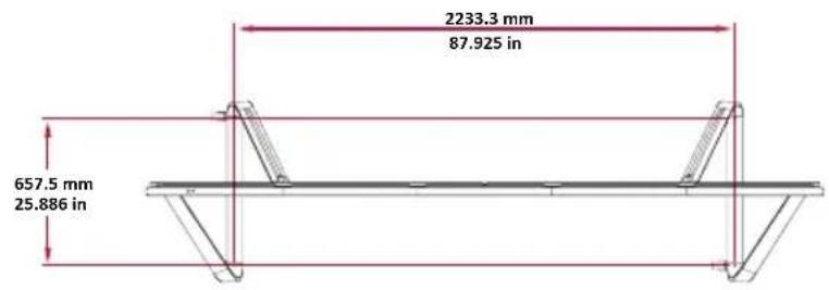
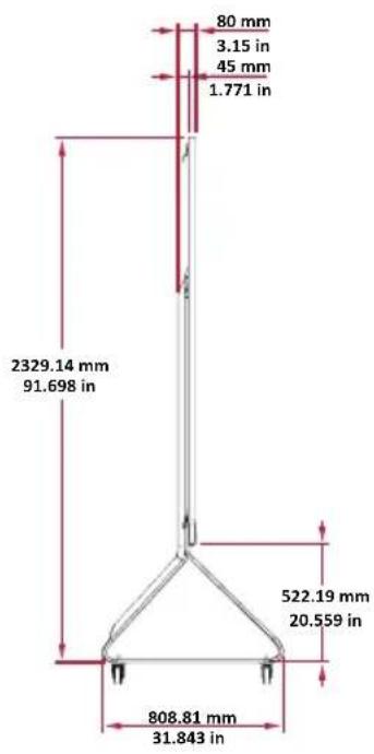
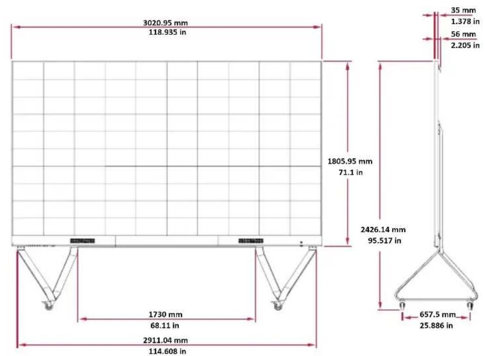
| Approximate Height | Approximately 2000 mm (depending on configuration) |
| Approximate Width | Approximately 1500 mm (depending on configuration) |
| Approximate Depth | Approximately 800 mm (depending on configuration) |
| Approximate Weight | Approximately 50 kg (parts only) |
| Maximum Load Capacity | Designed for LD135-151 display (estimated weight ~100 kg) |
| Main Functions | Floor-standing wall mount, modular installation for large format LED displays |
| Installation Type | Assembly required, floor mounting with casters |
| Box Contents | Left and right brackets, lower and upper crossbars, 14 M6x80 bolts, 8 M6x10 screws, 2 KM3x6 screws, Allen key, control box covers |
| Maintenance and Cleaning | Wipe with a soft, dry cloth. Do not use abrasive products. |
| Safety | Tip-over risk: do not roll over cables, uneven or sloping surfaces. Always lock wheels before moving. Use only with specified models. |
| Spare Parts and Repairability | Spare parts are available upon request. Repairs must be carried out by a qualified professional. |
Frequently Asked Questions - LDSTND001 VIEWSONIC
User questions about LDSTND001 VIEWSONIC
0 question about this device. Answer the ones you know or ask your own.
Ask a new question about this device
Download the instructions for your Monitor stand in PDF format for free! Find your manual LDSTND001 - VIEWSONIC and take your electronic device back in hand. On this page are published all the documents necessary for the use of your device. LDSTND001 by VIEWSONIC.
USER MANUAL LDSTND001 VIEWSONIC
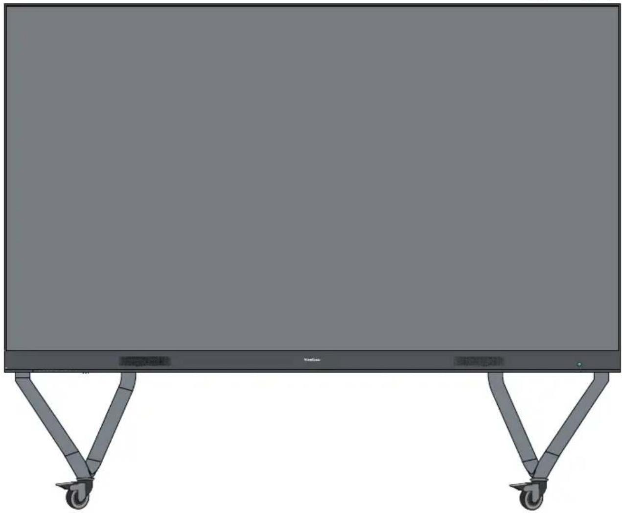
Floor Stand (LD-STND-001)
Compatible with LD135-151
All-in-one Direct View LED Display
Quick Start Guide
快速安装说明
快速入門指南
KpaTKoe pyKOBoCTBO no haay pa60tbi
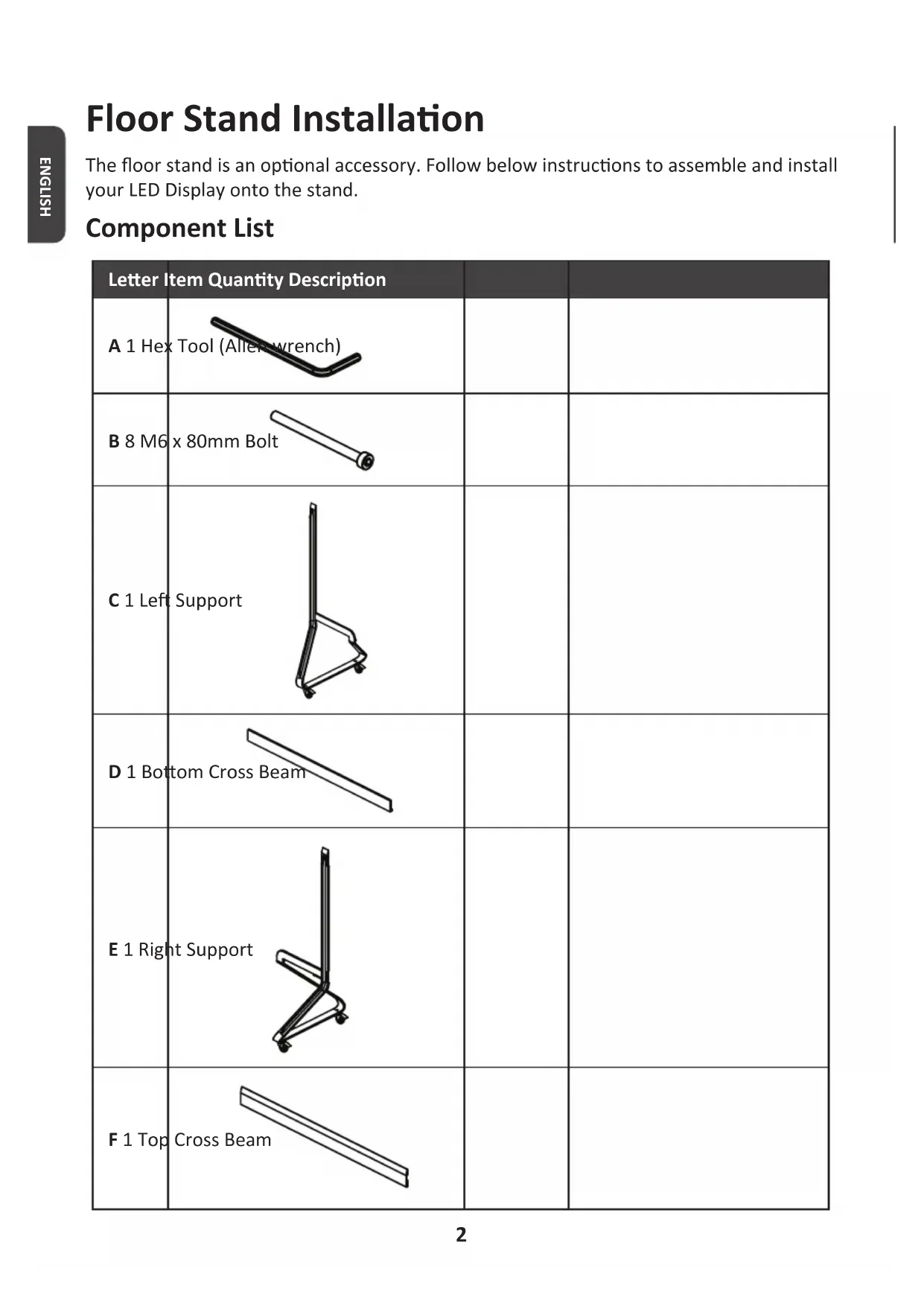
Floor Stand Installation
The floor stand is an optional accessory. Follow below instructions to assemble and install your LED Display onto the stand.
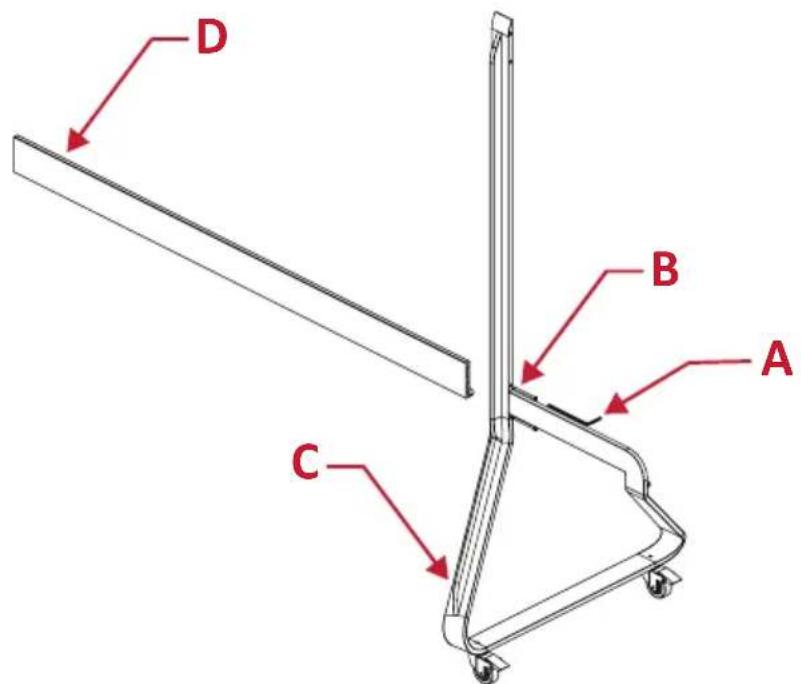
Component List
| Letter Item Quantity Description | |||
| A 1 Hex Tool (Aller-wrench) | |||
| B 8 M6 x 80mm Bolt | |||
| C 1 Left Support | |||
| D 1 Bottom Cross Beam | |||
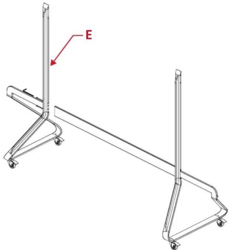
| E 1 Right Support | |||
| F 1 Top Cross Beam | |||
CAUTION
- This Stand is to be used with ViewSonic Direct View LD135-151 only. Using this stand with other models may cause instability and injury.
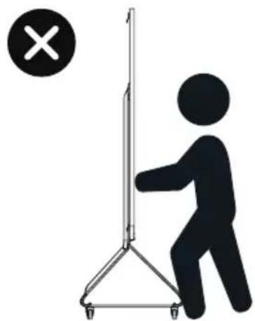
TIPPING HAZARD!
- DO NOT roll the stand over cable, uneven, dirty, soft, or high incline surfaces.
- DO NOT push the front of the display. Always unlock the wheels before moving. Failure to comply with this caution may result in equipment damage and personal injury.

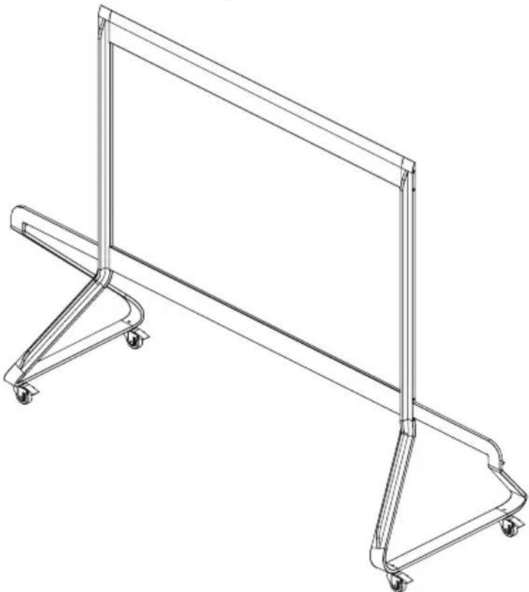
Assembling the Floor Stand
- Connect the Left Support "C" to the Bottom Cross Beam "D" with two (2) M6 x 80mm bolts "B" and using an Allen wrench "A".
- Connect the Right Support "E" with the Bottom Cross Beam with two (2) M6 x 80mm bolts.
- Connect the Top Cross Beam "F" to the Left and Right Supports with four (4) M6 x 80mm bolts.
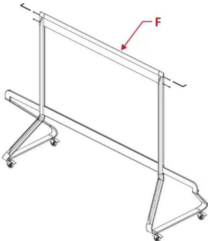
- Ensure all bolts are tightened properly with an Allen wrench.
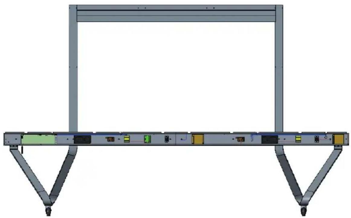
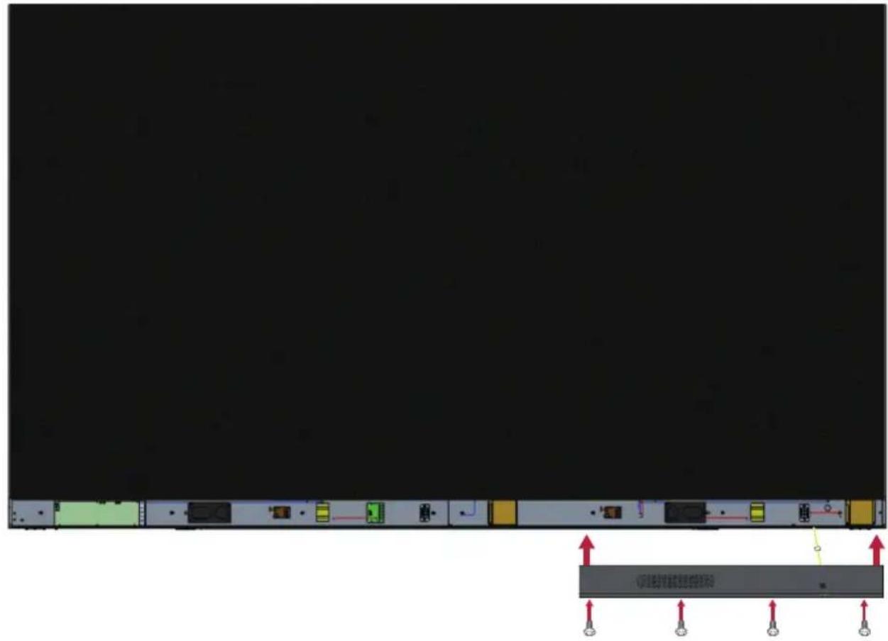
Connecting the System Control Box to the Floor Base
- Carefully unfold the System Control Box panel. Ensure the main system control board is on the left.
NOTE: Use caution as the System Control Box panel is separated into two pieces with wires attached.
- Align the System Control Box to the eight (8) holes on the Bottom Cross Beam and secure it with eight (8) M6 x 10mm screws.
- Install two (2) additional screws (M6x10mm) to connect the two halves of the System Control Box.
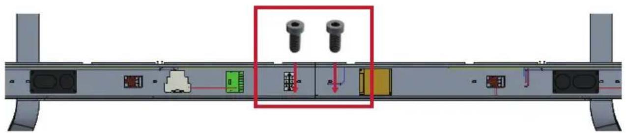
NOTE: Screws (M6x10mm) are placed in the accessory box of the LED Display.
Installing the Middle Cabinets
- Ensure the three (3) Mounting Brackets on the rear of the three (3) Middle Cabinets are positioned as shown below:
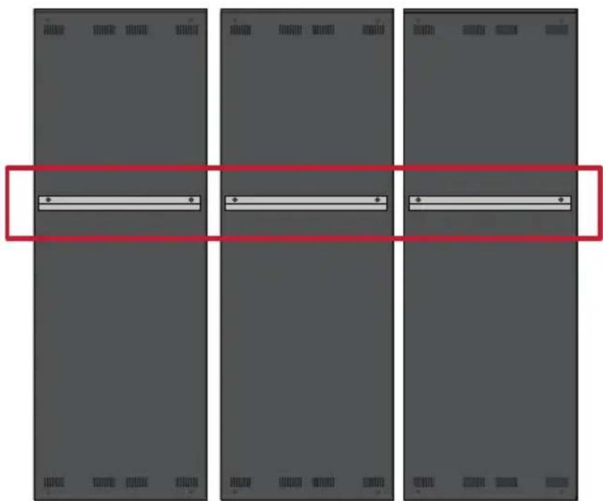
- Carefully lift a Cabinet up onto the Floor Stand, securing the Mounting Bracket into the support channel of the Top Cross Beam. The bottom of the Cabinet will rest on the Bottom Cross Beam.
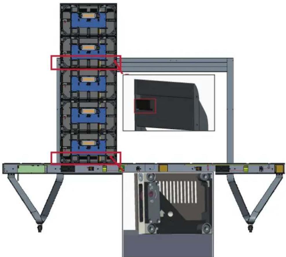
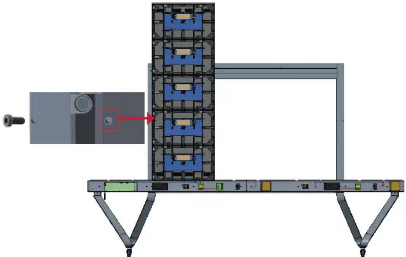
- Secure the Cabinet to the Support with the provided screws (M6x10mm).

- Push each Locking Bolt and lock each Hook with the hex tool to securely connect each cabinet together. It may be necessary to align the hole with an Allen wrench in order to engage the Locking Bolt.
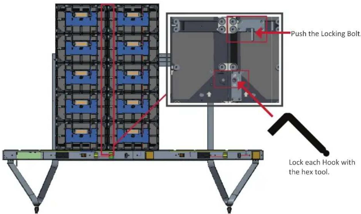
NOTE: There are five (5) Locking Bolts and 10 Hooks between each cabinet.
- Repeat Steps 2 4 for the remaining Middle Cabinets, Secure the Cabinet to the Right Support with the provided screws (M6x10mm).
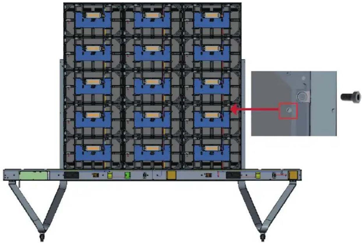
Installing the Left and Right Cabinet
- Carefully lift the Left and Right Cabinet up onto the Floor Stand, securing the Mounting Bracket into the support channel of the Top Cross Beam. The bottom of the Cabinet will rest on the Bottom Cross Beam.
NOTE: Ensure the holes of the Cabinet and the System Control Box are aligned.
- Push each Locking Bolt and lock each Hook with the hex tool to securely connect the Left and Right Cabinet to the Middle Cabinets.
- Secure the Left and Right Cabinet to the Support with the provided screws (M6x-10mm).
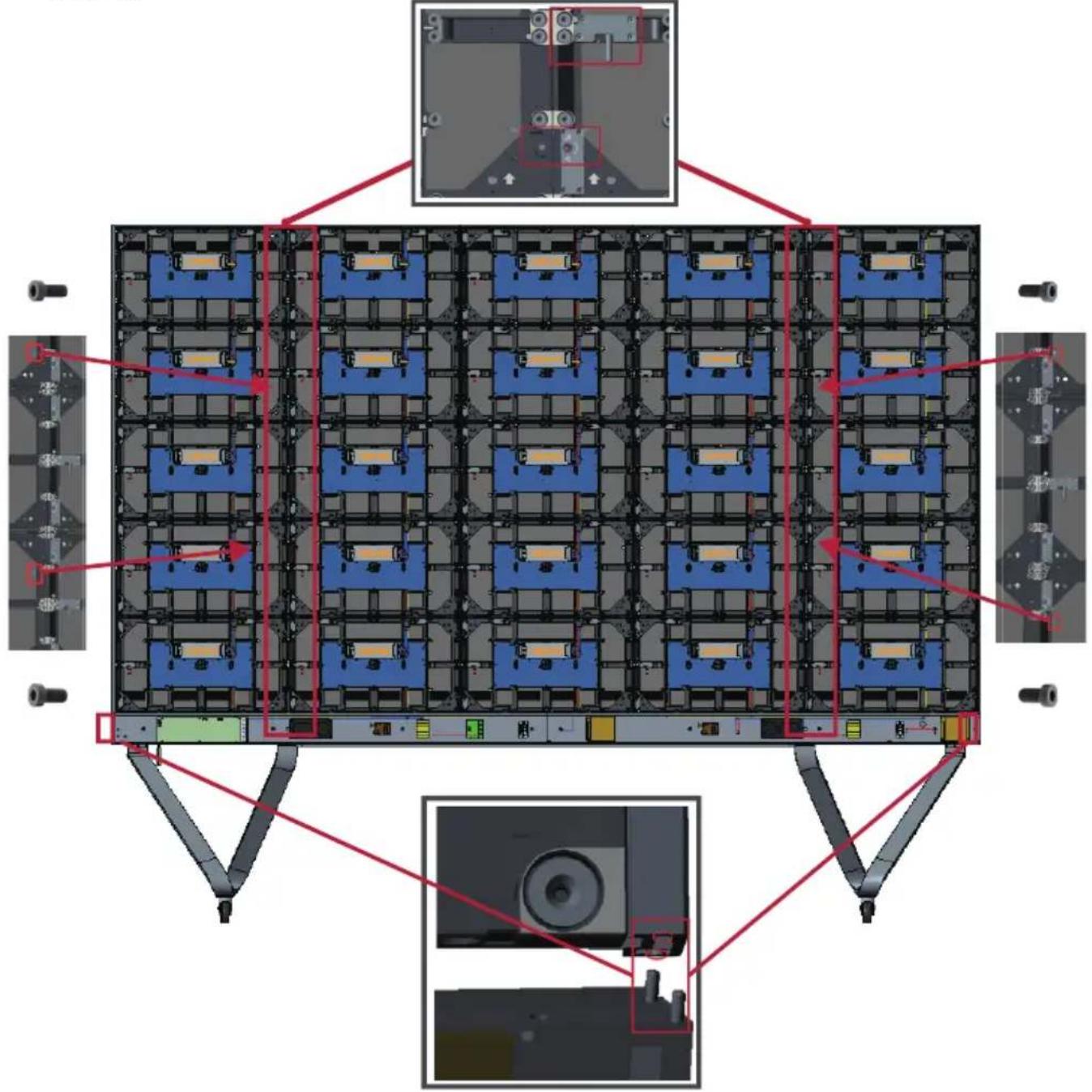
NOTE: There are five (5) Locking Bolts and 10 Hooks between each cabinet.
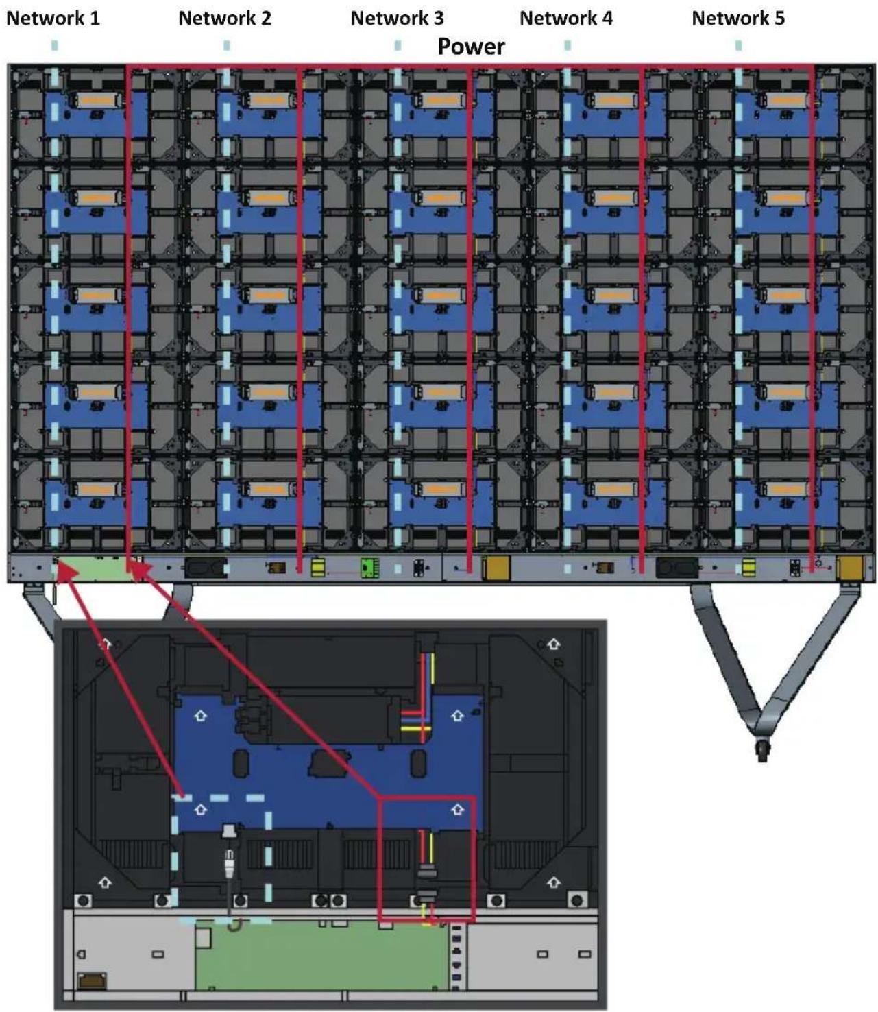
Connect the Network and Power Cables
Connect the Network and Power cables of each Cabinet to the System Control Box.
NOTE: There are five (5) Network and five (5) Power cables to connect.
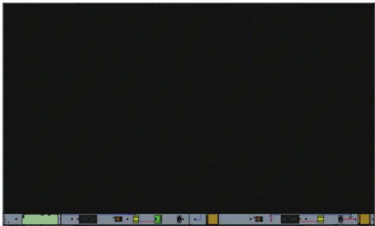
Installing the LED Modules
Install each LED Module onto the Cabinets, being sure to match the corresponding numbers on the Module to the Cabinet. Ensure each Module is flush and that there is little to no gap between each. It may be necessary to gently tap the module to make it flush.

CAUTION Please wear Anti-Static Gloves before handling the LED modules.
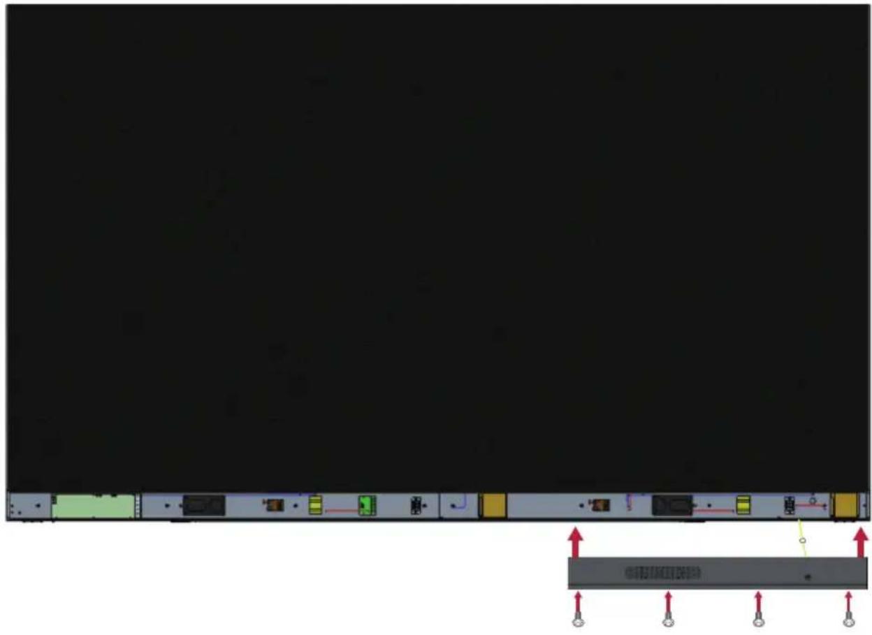
Installing System Control Box Covers
There are three (3) System Control Box Covers: Left, Middle, and Right.
- Begin by installing the Right Cover onto the System Control Box.
NOTE: Ensure the Power Button cable is connected to the System Control Box Power cable before securing the Cover.
- After connecting the Power Button cable, ensure the Right Cover is properly aligned with the System Control Box; then secure it with the 12 provided screws (KM3x6mm).
NOTE: Screws (KM3x6mm) are placed in the accessory box of the LED Display.

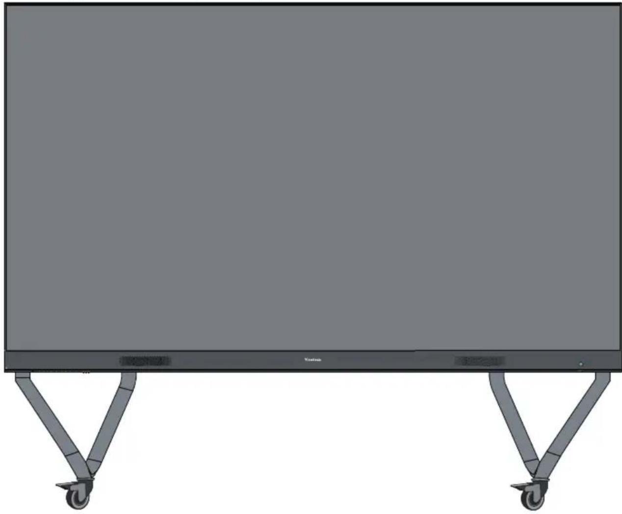
- Repeat the above steps for the Middle and Left Cover. Once all of the Covers are secured, your LED Display is ready to power on.
落地支架安装
YcTaHOBKa CBeToaNoJNbIX MoUJeN
YCTAHOBITE KaJdbi CBETOANDHbIM MOyIb B KOpNyc, y6eINBwncb, YTO COOTBeTCTByOUsne HOMepa, yka3aHHbIe Ha MOdyIe, coBnaJaOT co Homepom uKaΦa. Y6eINTecb, yTO KaJdbi MOyIb YCTAHOBJIeH BPOBeHc DpyrHMn I MeKdY HmMn Het 3a3opa. Bo3MOxHo, notpe6yeTcR OCTOpOxHO NOCTUaTb N O MOyIHO, YTO6bl BBipOBHraTb ero.

BHIMAHNE! NoxaIyIcTa, HadeHbTe aHTncTaTnueckne nepuATkn nepei pa60ToC o CBeToIDNoIDhBIMM MoDyIaMn.
YcTaHOBKa KpbIweK CnCTeMHoN KOpO6Kn YnpaBLeHna
Imeetc3 (tpn) KpbIshKncn CnCTeMHoN KOPO6Kn ynpabHeHna: JeBa, CpeHra n IpaBa.
- Hauhnte c yctaHOBKn npaBov KpbIshKn CnCTeMHoN KOPO6Kn ynpaBHeHna.
ПРИМЕЧАН. Перд зakpenlenem Крblшкуб endtecb,чTo Ka6eIb KhoNkn PtTahnnoPdKlnOueH K Ka6eHNo PtTahnna CnCTeMHoKopo6Kn ynpabLeHn.
aal 1 aal 1 aal 1 aal 1 aal 1 aal 1 aal 1 aal 1 aal 1 aal 1 aal 1 aal 1 aal 1 aal 1 aal 1 aal 1 aal 1 aal 1 aal 1 aal 1 aal 1 aal 1 aal 1 aal 1 aal 1 aal 1
LED
LED auiu uuaa auey 15 uuuu yu. uuyu uuyu uuyu uuyu uuyu uuyu uuyu uuyu uuyu uuyu uuyu uuyu uuyu uuyu uuyu uuyu uuyu uuyu uuyu uuyu uuyu uuyu uuyu uuyu uuyu uuyu uuyu uuyu uuyu uuyu uuyu uuyu uuyu uuyu
1 + u1 - 1 = ( 1 + u) u1 < 1 = u

ViewSonic
- Floor Stand (LD-STND-001)
- Floor Stand Installation
- Component List
- CAUTION
- TIPPING HAZARD!
- Assembling the Floor Stand
- Connecting the System Control Box to the Floor Base
- Installing the Middle Cabinets
- Installing the Left and Right Cabinet
- Connect the Network and Power Cables
- Installing the LED Modules
- Installing System Control Box Covers
- 落地支架安装
- YcTaHOBKa CBeToaNoJNbIX MoUJeN
- YcTaHOBKa KpbIweK CnCTeMHoN KOpO6Kn YnpaBLeHna
- ViewSonic
Brand : VIEWSONIC
Model : LDSTND001
Category : Monitor stand