ShowNET - Laser pointer Laserworld - Free user manual and instructions
Find the device manual for free ShowNET Laserworld in PDF.

| Product type | Network interface for laser projector |
| Brand | Laserworld |
| Model | ShowNET |
| Power supply | 5V DC power adapter (included) |
| Network connectivity | Ethernet 100 Mbit (RJ45) |
| Scanner output | 12-bit resolution (4096 positions per axis) |
| Color output | 8-bit resolution (256 values per channel: red, green, blue, intensity) |
| DMX input/output | DMX512 (non-isolated) |
| Storage | microSD card slot (ILDA 4/5 RGB formats) |
| Operating modes | Standalone, Demo, Master/Slave, DMX (DJ/Pro), ArtNet, ILDA Streaming |
| Compatible software | Showeditor (free), Showcontroller (professional) |
| Max scan speed | Approx. 100,000 points per second (pps) |
| Simultaneous management | Up to 16 ShowNET interfaces |
| ArtNet to DMX converter | Built-in |
| IP configuration | Static, DHCP or AutoIP |
| Maintenance and cleaning | Protect from moisture and dust. Clean with a dry cloth. Do not use solvents. |
| Safety | Professional use only. Observe local laser regulations. Do not use if visibly damaged. |
| Spare parts and repairability | Use only Laserworld spare parts. Contact the dealer or manufacturer for repairs. |
| General information | Manufacturer: Laserworld (Switzerland) AG, Kreuzlingerstrasse 5, CH-8574 Lengwil, Switzerland. Manual available in multiple languages. |
| Package contents | Network interface, power adapter, user manual, microSD card |
Frequently Asked Questions - ShowNET Laserworld
User questions about ShowNET Laserworld
0 question about this device. Answer the ones you know or ask your own.
Ask a new question about this device
Download the instructions for your Laser pointer in PDF format for free! Find your manual ShowNET - Laserworld and take your electronic device back in hand. On this page are published all the documents necessary for the use of your device. ShowNET by Laserworld.
USER MANUAL ShowNET Laserworld
ShowNET interface - the multi-feature DAC / ADC
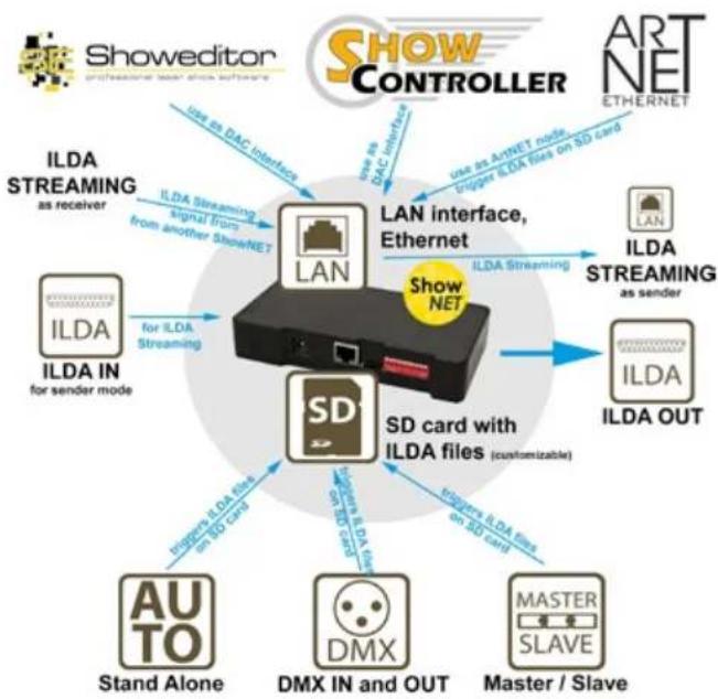
Network Control:
For network control (connecting the device to a Computer) please have a look at
chapter 5. Operation 4. Network operation
Netzwerkbetrieb:
Laserworld (Switzerland) AG reserves the right to make modifications to its products, attending to further technical developments. These modifications do not necessarily have to be recorded in each case.
This manual and its information have been made with due care. Laserworld AG cannot, however, take any responsibility for errata, bugs, or the resulting damages.
The brands and product names mentioned in this manual are trade marks or registered trade marks of their respective owners.
- Scope of delivery & details
- Preliminary warning notices
- Initial operations, safety instructions
- Device connections
- Operation
- Power Supply
Final statement
1. Scope of delivery & details
Please check if all listed parts are included and undamaged. Included in delivery:
1 x Network Interface 1 x Power Supply Unit
1x Manual 1x micro-SD Card
2. Preliminary warning notices
- Please use the network interface only according to these instructions.
- Do not use the network interface if there are any visible damages.
- Do not operate the network interface at high humidity, in rain or in dusty environments.
- Protect the network interface against dripping or splashing water.
3. Initial operations, safety instructions
- Make sure to use correct voltage; see information in this manual.
- Installation has to be done by technical experienced and qualified persons according to safety regulations of the respective country.
-
If the network interface has been exposed to great temperature changes, do not switch it on immediately. Condensation water may damage the network interface.
-
Never use dimmer, RC or other electronically switched sockets. Whenever possible, do not use the network interface together with large appliances (especially fog machines) on the same mains!
- Ensure sufficient ventilation and do not place the network interface on any warm or heat radiating surface.
Manual: Laserworld ShowNET - Network Interface Manual: Laserworld ShowNET - Network Interface
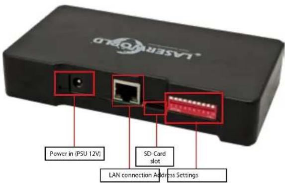
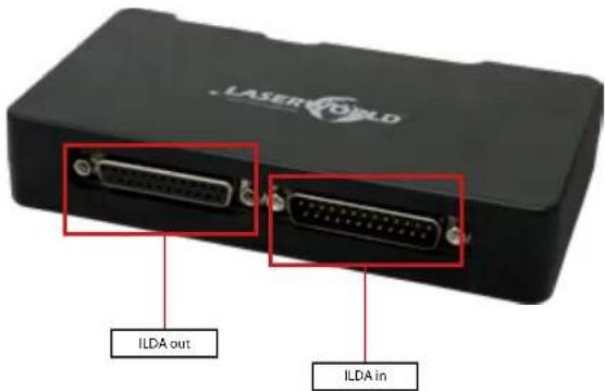
4. Device Connections

5. Operation
Technical overview:
X/Y scanner output with 12 bit resolution (4096 different positions on each axis)
- Up to 6 color output with 8 bit resolution (256 different values per
color channels): red, green, blue, intensity, user defined 1, user defined 2
- DMX512 input and output (non-isolated)
-10/100 Mbit Ethernet port
- Flexible IP address setting: fixed address, DHCP or AutoIP
- Micro-SD card slot for ILDA file playback (ILDA format code 5 RGB)
Built-in laser figures for stand alone operation
- Stand alone operation via DMX control or auto trigger
maximum scan speed of up to 150kpps
- Up to 16 devices can be used in parallel for multi-projector laser shows
The DIP switches can be used to select the desired operating mode. A change in the operation mode requires a restart of the device (unplug and replug the power supply). Do not change and DIP switch settings during operation, random and dangerous laser output can occur.
Operation Modes
(Firmware version: 20190520x - Admin tool: v1.33)
1. Download admin tool
For testing the show laser system and for other purposes, like uploading ILDA files to the SD card without the need for an external card reader, download the admin tool here: https://www.laserworld.com/shownet_mainboard
Open the „ShowNET-Admin_Tool.exe“ whenever this manual refers to the admin tool.
IMPORTANT: It's not possible to access the admin tool, when you are accessing the laser system via software (Showeditor, Showcontroller, etc.). When opening the admin tool while accessing the laser system in a non-direct-control operation mode, the admin tool asks to press on a button to switch to network mode for manual control.
2. Direct computer control
Connect the laser system to the ShowNET interface by using an ILDA cable. Do not connect the laser to the standard parallel port at the computer, but always use an appropriate ILDA interface. Connect the ShowNET Interface to your computer by using an ethernet cable (RJ45 standard). After that the laser can becontrolled by a show laser control software.
Standard network switches can be used to connect multiple laser systems at once.
Manual: Laserworld ShowNET - Network Interface Manual: Laserworld ShowNET - Network Interface

a) SHOWEDITOR - free laser show software
The Showeditor laser software is included with this ShowNET mainboard for free. It is a full feature laser control software with LIVE and Timeline control mode and many free laser shows included in delivery.
The software can be downloaded for free on:
https://wwwshoweditor.com
After downloading and installing the software, open the .exe file on the computer and use the software to operate the show laser system.
Details on installation and use of the software please find on the aforementioned website.
b) SHOWCONTROLLER - professional laser show and multimedia control software suite
The ShowNET mainboard fully supports the direct control of the laser via Showcontroller as well. Showcontroller is a mightly software tool with many professional features. It is very intuitive and thus easy to get started with, too.
The Software and a Demo Version can be downloaded on:
https://www.showcontroller.com
A license can be obtained from where this interface has been purchased.
3. Trigger own effects and ILDA files on the SD card
This network interface comes with a microSD card that can hold ILDA files with laser frames and animations that can be triggered in different ways. It is possible to just use the standard files that come with delivery or change the files to new, custom ones.
a) Upload own ILDA files to the SD card
Besides the possibility to just upload *.ild files to the microSD card with a standard card reader, it is also possible to remotely load ILDA files to the plugged in SD card via LAN without having to extract the SD card from the interface.
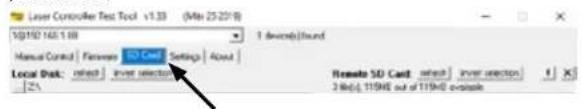
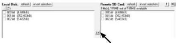
To change the ILDA files, open the admin tool and select the tab ,SD Card' as shown in the picture below:
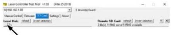
Select the folder with the ILDA files on the local hard drive by clicking on the button with the three points on it:
IMPORTANT: Custom laser files have to be stored in *.Ild format and must be named with a number from .000.1ld' to .255.1ld'. Each number represents a DMX value on the respective
page 8/54 page 9/54

fader.
To upload *.ld files greater than 6 MB, please use an external card reader. Otherwise the import may cause problems.
Select the *.ild files to be uploaded from the computer (left side) to the integrated SD card memory (right side).
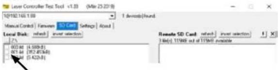
Click on the button with the two arrows to the right to upload the *.ild files to the integrated SD card. The files are copied and saved now.
Be aware that, due to the optimized data structure on the interface, the upload of ILDA files can take a while! (several minutes!)
IMPORTANT: It is not possible to upload any other data than *.ild files to the SD card!
Due to the huge number of available micro SD cards in the market, it cannot be guaranteed that all cards are compatible with the ShowNET Interface. The use of standard sized (max. 2GB) SD cards instead of high capacity SDHC or XDHC cards is recommended. It is also possible to copy the existing *.ild files on the SD card to the computer by selecting the files on the right side. Then click on the button with the two arrows to the left.
With the button, Invert selection' It is possible to select all files with just one click.
The button with the exclamation mark formats the SD card and thus deletes all existing files.
To delete single files, select the very *.ild file and then click on the button with the X^ on it (next to the one with the exclamation mark).
In case they got deleted by accident, the standard files card can be downloaded on
https://www.laser-interface.com
b) Stand-Alone Mode / Automatic Mode / Playback Mode
| Dip switch setting | ||||||||
| switch 1 2 3 4 5 6 7 8 9 10 | ||||||||
| On (1) / Off (0) | 0 0 0 0 0 1 0 1 0 0 | |||||||
In stand-alone mode the ILDA files on the plugged in SD card are triggered automatically.
Manual: Laserworld ShowNET - Network Interface Manual: Laserworld ShowNET - Network Interface

This setting is especially suitable for demo purposes or for fixed laser installations.
The stand-alone mode allows for additional advanced features: As standard, the standalone mode cycles through the ILDA files on the SD cards and plays them consecutively and in a general loop.
If DIP switch 4 is activated too, the stand alone mode only plays one specific ILDA file and just loops this file.
| switch 1 2 3 4 5 6 7 8 9 10 | |||||||
| On (1) / Off (0) | 0 0 1 0 1 0 1 0 0 |
Dip switch 1 can be used to step to the next file (just switch DIP switch 1 to on, then to off again)
Dip switch 2 can be used to step to the previous file (just switch DIP switch 2 to on, then to off again)
c) Demo Mode / Automatic Animation
| switch 12345678910 | |||||||
| On (1)/Off (0)000100010 |
In demo mode the ILDA files on the plugged in SD card are triggered automatically. The ILDA files are not only played back like in the stand alone mode, but they are also automatically animated by ShowNET's internal intelligence. This creates dynamic animations, even if only static frames are on the SD card.
This setting is especially suitable for demo purposes.
MASTERUnit:
d) Master-Slave-Mode: Demo Mode
| switch 12345678910 | |||||||
| On (1)/Off(0)000010010 |
SLAVE units:
| switch 1 2 3 4 5 6 7 8 9 10 | |||||||
| On (1)/Off (0) 0 0 0 0 1 1 0 0 |
To have the same effects show on all connected units, it is required to have the same pattern sets on all SD cards inside the units.
e) ArtNet Operation
IMPORTANT: ArtNet operation requires the ShowNET interface to be connected in a DHCP environment (router with Integrated switch is recommended). The address handling must be managed through DHCP. For questions on DHCP, please refer to 4.1. DHCP Mode.
Only ShowNET interfaces and the ArtNet controller must be used in the same network. Avoid using other network devices in the same network.

Use the dip switches to assign a certain address like in DMX mode:
| switch 1 2 3 4 5 | 6 7 8 | 9 10 | ||||||||
| Binary DMX channel offset | 1 | 2 | 4 | 8 | 16 | 32 | 64 | 128 | 256 | Switch 10 has to be ON (up) for ArtNet operation |
To activate ArtNet trigger, open the admin tool and navigate to the tab, Settings'. Then change the Data source for internal DMX effects' to ArtNet input' as seen in the picture below:
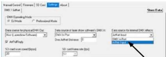
Click on,Store Data to save the changes. Click on,OK twice and wait until another window opens that asks to restart the ILDA interface. To do so, switch the laser system off and on again.
See the details on DMX Mode below for more information:
f)DMX Modes
| switch 1 2 3 4 5 | 6 7 8 | 9 10 | ||||||||
| Binary DMX channel offset | 1 | 2 | 4 | 8 | 16 | 32 | 64 | 128 | 256 | Switch 10 has to be ON (up) for DMX mode |
There are two DMX / ArtNet configuration modes:
(1) DJ Mode & (2) Professional Mode.
The DJ mode is more basic and comes with some pre-configured automations. It is suitable for most users.
The Professional mode comes with some advanced features and requires deeper knowledge of DMX / ArtNet to be handled properly.
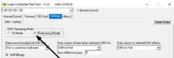
DJ mode is the standard option. To use the Professional mode, open the admin tool and navigate to the tab .Settings'
Manual: Laserworld ShowNET - Network Interface Manual: Laserworld ShowNET - Network Interface

Change the option.
Click on Store Data to save your changes. Click on OK twice and wait until another window opens that asks to restart the ILDA interface. To do so, switch the laser system off and on again.
(1) DJ Mode
To get laser output, DMX channel 1 needs to have a value greater than 0 (recommended 64 to 192)
| Channel Mode Value Function | |||
| 1 Intensity DJ 0 Laser off | |||
| 1 - 255 Increase intensity (full intensity = 255) | |||
| 2 Pattern selection DJ 0 B | blackout (000) | 1 - 255 Display patterns from SD card:1 = 001.ild2 = 002.ild... and so onIf no pattern is assigned to a number = blackout | |
| 3 Pattern speed(Framerate) | DJ 0 - 15 | Standard speed: 50 fps | |
| 16 - 255 | Increasing speed from 0 fps to 100 fps | ||
| 4 Size | DJ 0 - 127 | Decreasing size X + Y-axis | |
| 128 - 191 | Decreasing size X-axis | ||
| 192 - 255 | Decreasing size Y-axis | ||
| 5 Automatic size | DJ 0 - 63 | Full size | |
| 64 - 127 | Changing size automatically X + Y-axis(increasing speed) | ||
| 128 - 191 | Changing size automatically X-axis(increasing speed) | ||
| 192 - 255 | Changing size automatically Y-axis(increasing speed) | ||
| 6 Rotate | DJ 0 - 192 | Manual rotatio | |
| 193 - 224 | Automatic rotation anti-clockwise(increasing speed) | ||
| 225 - 255 | Automatic rotation clockwise(increasing speed) | ||
| 7 Position X-axis coarse | DJ 0 - 255 | = center | |
| 8 Position X-axis fine DJ 0 | - 255 | ||
| 9 Position Y-axis coarse | DJ 0 - 255 | = center | |
| 10 Position Y-axis fine | DJ 0 - 255 | ||

| Channel Mode Value Function | |||
| 11 Color effects | DJ 0 - 15 | Show pattern in original colors | |
| 16 - 79 Show pattern in different colors (monochrome) | |||
| 80 - 143 | Re-color effects:Original colors are replaced by new colors | ||
| 144 - 255 | Automatic change of re-color effects | ||
| 12 Color effects extended | DJ 0 - 127 | smooth color fade effect to the re-color effectValue of channel 11 must be >1S! | |
| 128 - 192 | Blocking color effect to the re-color effectValue of channel 11 must be >1S! | ||
| 193 - 255 | Automatic change of color fade effects | ||
| 13 Strobe | DJ 0 - 15 | None | |
| 16 - 255 | Increasing strobe effect | ||
| 14 Operation mode | DJ 0 - 19 | DMX | |
| 20 - 83 Automatic position X & Y-axis | |||
| 84 - 147 | Automatic position X-axis | ||
| 148 - 211 | Automatic position Y-axis | ||
| 212 - 233 | Demonstration mode | ||
| 234 - 255 | Sound-to-light | ||
| 15 Scan speed | DJ 0 - 31 | Default | |
| 32 - 255 | Increasing scan speed (from 5 kpps to 30 kpps)ATTENTION: If you're unsure about the maxi-mum scan speed, stay with the default setting! | ||
| 16 Safety zone size | DJ 0 - 63 | Size of horizontal safety zoneSafety zone is the bottom side | |
| 64 - 127 | Size of horizontal safety zoneSafety zone is the upper side | ||
| 128 - 191 | Size of vertical safety zoneSafety zone is the left side | ||
| 192 - 255 | Size of the vertical safety zoneSafety zone is the right side | ||
| 17 Safety zone intensity | DJ 0 No reduction | ||
| 1 - 128 Decrease brightness up to half brightness | |||
| 129 - 255 | Decrease brightness up to blackout | ||
| 18 Blanking | DJ 0 - 192 | Manual select how much of the laser pattern shall be blanked | |
| 193 - 255 | Automatic blanking (increasing speed) | ||
| 19 Blankshift | DJ 0 - 192 | Manual select the pattern part the blanking of channel 18 shall be applied to | |
| 193 - 255 | Automatic blank shift (increasing speed) | ||
Manual: Laserworld ShowNET - Network Interface Manual: Laserworld ShowNET - Network Interface

(2) Professional Mode
| Channel Mode Value Function | |||
| 1 Intensity Prof. 0 Laser of | |||
| 1 - 255 Increase | case intensity (full intensity = 255) | ||
| 2 Pattern selection Prof. 0 | Blackout (000 Ild must not exist) | ||
| 1 - 255 Disp | ay patterns from SD card:1 = 001.ILD2 = 002.ILD... and so onIf no pattern is assigned to a number = blackout | ||
| 3 Pattern speed(Framerate) | Prof. 128 Sta | ard speed | 50 fps |
| 0 - 127 Increasing speed from 0 fps tp 50 fps | |||
| 129 - 255 Increasing speed from 50 fps to 100 fps | |||
| 4 Position X-axis coarse P | of. 0 - 255 Fro | from left (0) to right (25S); center = 128 | |
| 5 Position X-axis fine | Prof. 0 - 255 | ||
| 6 Position Y-axis coarse | Prof. | 0 - 25S | From bottom (0) to top (25S); center = 128 |
| 7 Position Y-axis fine | Prof. 0 - 255 | ||
| 8 Rotation coarse | Prof. 0 - 255 | Rotate; 0° = 128 | |
| 9 Rotation fine Prof. 0 - 255 | |||
| 10 Size X-axis | Prof. 0 - 255 | From maximum (0) to minimum (25S) | |
| 11 Size Y-axis | Prof. | 0 - 25S | From maximum (0) to minimum (25S) |
| 12 Inversion | Prof. 0 - 63 | None | |
| 64 - 127 | Invert X-axis | ||
| 128 - 191 Invert Y-axis | |||
| 192 - 255 Invert X + Y-axis | |||
| 13 Color Selection | Prof. | 0 - 15 | Original pattern colors |
| 16 - 207 | Color selection from red (16) through yellow(48), green (80), cyan (112) and blue (144) up topurple (176) with color mixtures in between. | ||
| 208 - 223 White with half intensity for each color channel | |||
| 224 - 239 White with full intensity for each color channel | |||
| 240 - 255 Enables channels 14 - 16 to select a specific hue | |||
| 14 Red | Prof. 0 - 255 | Increase intensityredOnly active if the value of channel 13 is 240 - 255 | |
| 15 Green | Prof. 0 - 255 | Increase intensitygreenOnly active if the value of channel 13 is 240 - 255 | |
| 16 Blue | Prof. 0 - 255 | Increase Intensity blueOnly active if the value of channel 13 is 240 - 255 | |

| Channel Mode Value Function | |||
| 17 Strobe | Prof. 0 - 15 | None | |
| 16 - 255 | Increasing strobe effect | ||
| 18 Scan speed | Prof. 0 - 15 | Default | |
| 16 - 255 | Increasing scan speed (from 5 kpps to 40 kpps) | ||
| 19 Safety zone size | Prof. | 0 - 63 | Size of horizontal safety zoneSafety zone is the bottom side |
| 64 - 127 | Size of horizontal safety zoneSafety zone is the upper side | ||
| 128 - 191 Size of vertical safety zoneSafety zone is the left side | |||
| 192 - 255 Size of vertical safety zoneSafety zone is the right side | |||
| 20 Safety zone intensity | Prof. | 0 - 255 | From max intensity (0) to no intensity (255) |
| 21 Color balancing red(for white balance) | Prof. 0 - 255 | From max intensity (0) to no intensity (255)Master to channel 14! | |
| 22 Color balancing green (for white balance) | Prof. 0 - 255 | From max intensity (0) to no intensity (255)Master to channel 15! | |
| 23 Color balancing blue(for white balance) | Prof. 0 - 255 | From max intensity (0) to no intensity (255)Master to channel 16! | |
| IMPORTANT: Channels 24 - 34 are reserved for future features and must not be assigned | |||
Important Note: Operate scanners/galvos only at appropriate speed according to the respective scan angle. Too high scan speed will damage the scanning system.
Manual: Laserworld ShowNET - Network Interface Manual: Laserworld ShowNET - Network Interface

4. Network Operation
Important:
Only ShowNET interfaces and potentially an ArtNet controller must be used in the same network. Avoid using other network devices in the same network.
Avoiding connectivity issues, Troubleshooting:
- Make sure that no firewall is blocking the network traffic between the computer and the show laser device. The firewall has to be configured to grant network access to the laser show software.
- if the network connection does not work, try to temporarily disable the firewall. If this helps, create a matching rule and re-activate the firewall.
- Whenever the DIP switch settings for the network mode are changed (for example, change static IP address or switch from DHCP to AutolIP mode), the ShowNET device has to be restarted (disconnect it from the mains and plug it in again).
- The interface has to be connected to a 100Mbit or Gigabit Ethernet LAN. 10Mbit Ethernet is not suitable.
The use of WIFI (WLAN) is not recommended. This will result in decreased output performance and unsafe operation.
Attention - maximum cable length:
When using ethernet cables with RJ45 connection, always pay attention to the maximum length of the very cable. E.g.:
Cat 5e = max. 100 m
Cat 6=max.50m
Cat 7 = max. 50 m
Cat 8 = max. 30 m
You can use normal network switches to amplify the signal and extend the range!
Without amplification of the signal (e.g., via a switch) it is recommended to use fiber transmission as soon as longer distances are required.
a) DHCP Mode
| Dip switch setting | ||||||||
| switch 1 2 3 4 5 6 7 8 9 10 | ||||||||
| On (1) / Off (0) | 0 0 0 0 0 0 0 0 0 | 0 0 0 0 | 0 0 0 0 | 0 0 0 0 | 0 0 0 0 | 0 0 0 0 | 0 0 0 0 | |
In this mode, the IP address is provided by a DHCP server. Therefore, a DHCP server has to be available in the network. For example, this could be a cheap 100MBit network router with integrated DHCP server. This option does not work if there is no device in the same network that can distribute and manage network addresses as DHCP! In this case, try AutoIP as connection method (e.g. If the interface is directly connected to the computer)!

b) AutoIP
| switch 1 2 3 4 5 6 7 8 9 10 | |||||||
| On (1) / Off (0) 0 0 0 0 1 0 0 0 0 |
In this mode, the IP address is negotiated automatically without the need for a DHCP server. A Windows computer with enabled AutolIP is necessary to use this feature. In Windows 7, 8 and 10, AutolIP is enabled by default. In Windows XP it has to be enabled manually. Before trying to connect a ShowNET to the computer, make sure that the AutolIP feature is enabled. If AutolIP is selected, but there is a DHCP server in the network (e.g. in a router), the IP assignment cannot work sometimes. Use DHCP mode in this case.
c) Static IP address
Using a static IP address is the most stable option for network control. The IP address consists of 4 numbers, seperated by a point. The first two number are always 192.168 and cannot be changed. The last two numbers (adr1 and adr2) can be configured with DIP switches. The resulting IP address will be something like
192.168.adr1.adr2
| switch 1 2 3 4 5 6 7 8 9 10 | |||||||||
| On (1) / Off (0) | 000 - adr2 = 501000 - adr2 = 5101000 - adr2 = 521100 - adr2 = 530010 - adr2 = 541010 - adr2 = 550110 - adr2 = 561110 - adr2 = 570001 - adr2 = 581001 - adr2 = 590101 - adr2 = 601101 - adr2 = 610011 - adr2 = 621011 - adr2 = 630111 - adr2 = 641111 - adr2 = 65 | 00 - adr1 = 010 - adr1 = 101 - adr1 = 211 - adr1 = 254 | 1000 | ||||||
The Windows computer needs to have an IP address within the same network subnet.
Example:
| switch 1 2345678910 | ||||||||
| On(1)/Off(0)101001000 |
This will assign IP address 192.168.0.61 to the ShowNET interface.
Assign a different IP address inside the same subnet to the Windows computer, for example
The Laserworld ShowNET interface is capable to act as range extender for ILDA signals by transforming an incoming ILDA signal on the ILDA IN interface to a standard UDP network signal and transferring this signal back to standard ILDA in a receiver unit (obviously an external ShowNET interface is required as sender for this kind of application). Do NOT send the signal over WiFi, this transmission method is not suitable in a professional environment.
Sender-Receiver configuration for ILDA over LAN, range extender use
The sender uses an IP address range between 192.168.2.70 and 192.168.2.85 and transmits the signal to a receiver that has addresses in the range between 192.168.2.50 and 192.168.2.65. The specific IP addresses need to be set with DIP switches. Make sure there are no other devices in the same network that use the same IP addresses.
| Dip switch setting | ||||||||||
| switch 1 | 23456789 | 10 | ||||||||
| On (1) / Off (0) | 0000 -> IP sender: 192.168.2.70 sends to 192.168.2.50001 -> IP sender: 192.168.2.71 sends to 192.168.2.5100 -> IP sender: 192.168.2.72 sends to 192.168.2.520011 -> IP sender: 192.168.2.73 sends to 192.168.2.530100 -> IP sender: 192.168.2.74 sends to 192.168.2.540101 -> IP sender: 192.168.2.75 sends to 192.168.2.550110 -> IP sender: 192.168.2.76 sends to 192.168.2.560111 -> IP sender: 192.168.2.77 sends to 192.168.2.571000 -> IP sender: 192.168.2.78 sends to 192.168.2.581001 -> IP sender: 192.168.2.79 sends to 192.168.2.591010 -> IP sender: 192.168.2.80 sends to 192.168.2.601011 -> IP sender: 192.168.2.81 sends to 192.168.2.61110 -> IP sender: 192.168.2.82 sends to 192.168.2.621101 -> IP sender: 192.168.2.83 sends to 192.168.2.631110 -> IP sender: 192.168.2.84 sends to 192.168.2.641111 -> IP sender: 192.168.2.85 sends to 192.168.2.65 | |||||||||
Example:
Sender IP address setting:
| switch | 1 | 2 | 3 | 4 | 5 | 6 | 7 | 8 | 9 | 10 |
| On (1) / Off (0) | 0 | 0 | 0 | 1 | 0 | 0 | 1 | 1 | 0 | 0 |
This assigns IP address 192.168.2.71 to the Sender.
The corresponding receiver needs this IP address setting:
| switch | 1 | 2 | 3 | 4 | 5 | 6 | 7 | 8 | 9 | 10 |
| On (1) / Off (0) | 0 | 0 | 0 | 1 | 1 | 0 | 1 | 1 | 0 | 0 |
This assigns IP address 192.168.2.51 to the receiver.
The only difference between sender and receiver configuration is dip switch 5, which is 0 for the sender and 1 for the receiver.
6. Power Supply
Use the power supply (included in delivery) to connect the ShowNET Interface to mains.
page 18/54 page 19/54

Final statement
Product and package leaving warehouse without faults. Users have to follow the local safety regulations and warnings of this manual. Damages through inappropriate use do not underlie the sphere of influence of manufacturer or dealer. Therefore no liability or warranty will be taken over. We cannot inform you in case of changes of this manual. If you have any questions, please contact your dealer.
For service please contact your dealer or Laserworld. Please use only spare parts of Laserworld. Subject to change without notice. Because of the vast amount of data we cannot guarantee any correctness of given information.
Laserworld (Switzerland) AG
Kreuzlingerstrasse 5
8574 Lengwil
Switzerland
Registered office:
8574 Lengwil/Switzerland
Company number: CH-440.3.020.548-6
Commercial Registry Kanton Thurgau
CEO: Martin Werner
VAT no. (Switzerland): 683 180
UID (Switzerland):CHE-113.954.889
VAT no. (Germany): DE 258030001
WEEE-Reg.-No. (Germany): DE 90759352
www.laserworld.com
info@laserworld.com
representative according to EMVG:
Managing Director: Martin Werner
Muhlbachweg 2
83626 Valley / Germany

Manual: Laserworld ShowNET - Network Interface Manual: Laserworld ShowNET - Network Interface

Inhaltverzeichnis:
(Firmware:20190520x-Admin tool:v1.33)
https://wwwshoweditor.com
https://www.showcontroller.com
page 26/54 page 27/54

representative according to EMVG:
Managing Director: Martin Werner
Muhlbachweg 2
83626 Valley / Germany


Table des matieres:
(Lo version firmware: 20190520x - Admin tool: v1.33)
https://wwwshoweditor.com
https://www.showcontroller.com
| switch 1 2 3 4 5 | 6 7 8 | 9 10 | ||||||||
| Binary DMX channel offset | 1 2 | 8 16 | 32 64 | 128 | 2 | 56 Switch 1 | 0 has | a be CN (up) | for ArtNet operation |
| switch 1 2 3 4 5 | 6 7 8 | 9 10 | ||||||||
| Binary DMX channel offset | 1 2 4 | 8 16 | 32 64 | 128 | 256 | Switch 1 | 0 has to be ON (up) | for DMX mode | ||
Changez la selection.
Managing Director: Martin Werner
Muhlbachweg 2
83626 Valley/Allemagne