USER MANUAL BDL500S BLACK & DECKER
BEFORE RETURNING THIS PRODUCT
FOR ANY REASON PLEASE CALL
1-800-544-6986
IF YOU SHOULD HAVE A QUESTION OR EXPERIENCE A PROBLEM WITH YOUR BLACK & DECKER PRODUCT,
CALL 1-800-544-6986
BEFORE YOU CALL, HAVE THE FOLLOWING INFORMATION AVAILABLE, CATALOG No., TYPE No., AND
DATE CODE (e.g. 20000130M). IN MOST CASES, A BLACK & DECKER REPRESENTATIVE CAN RESOLVE
YOUR PROBLEM OVER THE PHONE. IF YOU HAVE A SUGGESTION OR COMMENT, GIVE US A CALL.
YOUR FEEDBACK IS VITAL TO BLACK & DECKER.
SAVE THIS MANUAL FOR FUTURE REFERENCE.
VEA EL ESPAÑOL EN LA CONTRAPORTADA.
⚠ WARNING: Read and understand all instructions. Failure to follow all instructions listed below may result in electric shock, fire and/or serious personal injury.
SAVE THESE INSTRUCTIONS
Safety Instructions
⚠️ DANGER: Laser Radiation, avoid direct eye exposure, serious eye injury can result.
- Do not use optical tools such as a telescope or transit to view the laser beam.
- Position the laser so unintentional eye contact will be avoided.
- Do not operate the laser around children or allow children to operate the laser.
- Do not disassemble. Modifying the product in any way can increase the risk of laser radiation.
⚠ WARNING: Use of controls or adjustments or performance of procedures other than those specified in this manual may result in hazardous laser radiation exposure.
- Do not operate in explosive atmospheres, such as in the presence of flammable liquids, gases, or dust.
- Use only with the specifically designated batteries. Use of any other batteries may create a risk of fire.
- Store idle product out of reach of children and other untrained persons. Lasers are dangerous in the hands of untrained users.
- Use only accessories that are recommended by the manufacturer for your model. Accessories that may be suitable for one laser, may create a risk of injury when used on another laser.
• Repairs and servicing MUST be performed by a qualified repair facility. Repairs performed by unqualified personnel could result in serious injury.
- Do not remove or deface warning labels. Removing labels increases the risk of exposure to radiation.
- For indoor use only.
- This product is intended for use in a temperature range of 41^(5^) - 104^(40^) .
⚠ WARNING: SHOCK HAZARD. Use caution when drilling, nailing or cutting into walls, floors and ceilings which may contain electrical wiring or pipes. Always turn off the power when working near electrical wires.
Liquid Crystal Display (First Aid Measures)
- If liquid crystal comes in contact with your skin:
Wash area off completely with plenty of water. Remove contaminated clothing.
- If liquid crystal gets into your eye: Flush the affected eye with clean water and then seek medical attention.
- If liquid crystal is swallowed: Flush your mouth thoroughly with water. Drink large quantities of water and induce vomiting. Then seek medical attention.
The label on your tool may include the following symbols.
V volts
mW milliwatts
nm....wavelength in
.....nanometers
IIIa....Class IIIa Laser
For your convenience and safety, the following labels are on your laser.
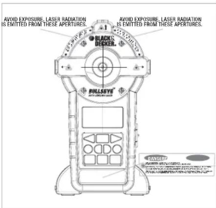
FCC WARNING:
This device complies with part 15 of the FCC Rules. Operation is subject to the following two conditions:
(1) This device may not cause harmful interference, and
(2) This device must accept any interference received, including interference that may cause undesirable operation.
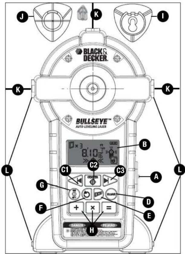
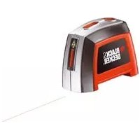
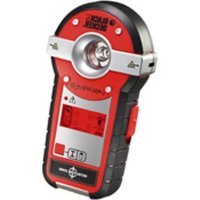
FEATURES
A.) Laser On/Off Button
B.) LCD Screen
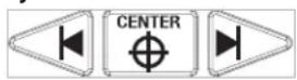
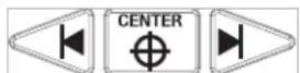
C1, C2, C3) Left, Center, Right Measurement Buttons
D.) Clear Button
E.) Accu-Spacing Button
F.) Repeat Distance Button
G.) On / Off Button
H.) Plus, Times, Equals Button
I.) Wall Attachment - Hanging Cone (keyhole)
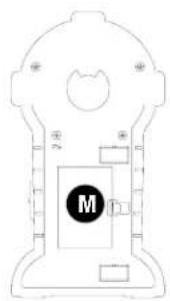
M.) Battery Compartment Cover (back side of unit)
natural_image
Pure technical diagram of a mechanical or electrical component with no visible text, numbers, or symbols.
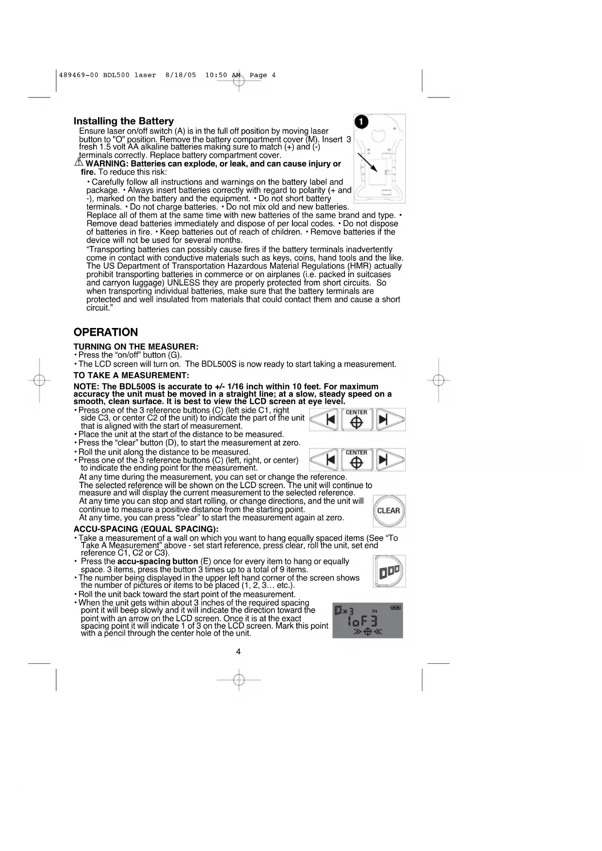
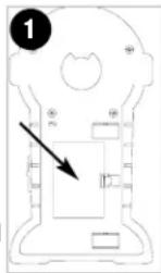
Installing the Battery
Ensure laser on/off switch (A) is in the full off position by moving laser button to "O" position. Remove the battery compartment cover (M). Insert 3 fresh 1.5 volt AA alkaline batteries making sure to match (+) and (-) terminals correctly. Replace battery compartment cover.
⚠ WARNING: Batteries can explode, or leak, and can cause injury or fire. To reduce this risk:
- Carefully follow all instructions and warnings on the battery label and package. • Always insert batteries correctly with regard to polarity (+ and -), marked on the battery and the equipment. • Do not short battery terminals. • Do not charge batteries. • Do not mix old and new batteries.
Replace all of them at the same time with new batteries of the same brand and type. Remove dead batteries immediately and dispose of per local codes. Do not dispose of batteries in fire. Keep batteries out of reach of children. Remove batteries if the device will not be used for several months.
"Transporting batteries can possibly cause fires if the battery terminals inadvertently come in contact with conductive materials such as keys, coins, hand tools and the like. The US Department of Transportation Hazardous Material Regulations (HMR) actually prohibit transporting batteries in commerce or on airplanes (i.e. packed in suitcases and carryon luggage) UNLESS they are properly protected from short circuits. So when transporting individual batteries, make sure that the battery terminals are protected and well insulated from materials that could contact them and cause a short circuit."
OPERATION
TURNING ON THE MEASURER:
- Press the "on/off" button (G).
- The LCD screen will turn on. The BDL500S is now ready to start taking a measurement.
TO TAKE A MEASUREMENT:
NOTE: The BDL500S is accurate to +/- 1/16 inch within 10 feet. For maximum accuracy the unit must be moved in a straight line; at a slow, steady speed on a smooth, clean surface. It is best to view the LCD screen at eye level.
- Press one of the 3 reference buttons (C) (left side C1, right side C3, or center C2 of the unit) to indicate the part of the unit that is aligned with the start of measurement.
- Place the unit at the start of the distance to be measured.
- Press the "clear" button (D), to start the measurement at zero.
- Roll the unit along the distance to be measured.
- Press one of the 3 reference buttons (C) (left, right, or center) to indicate the ending point for the measurement.
At any time during the measurement, you can set or change the reference.
The selected reference will be shown on the LCD screen. The unit will continue to measure and will display the current measurement to the selected reference.
At any time you can stop and start rolling, or change directions, and the unit will continue to measure a positive distance from the starting point.
At any time, you can press "clear" to start the measurement again at zero.

ACCU-SPACING (EQUAL SPACING):
- Take a measurement of a wall on which you want to hang equally spaced items (See “To Take A Measurement” above - set start reference, press clear, roll the unit, set end reference C1, C2 or C3).
- Press the accu-spacing button (E) once for every item to hang or equally space. 3 items, press the button 3 times up to a total of 9 items.
- The number being displayed in the upper left hand corner of the screen shows the number of pictures or items to be placed (1, 2, 3... etc.).
- Roll the unit back toward the start point of the measurement.
- When the unit gets within about 3 inches of the required spacing point it will beep slowly and it will indicate the direction toward the point with an arrow on the LCD screen. Once it is at the exact spacing point it will indicate 1 of 3 on the LCD screen. Mark this point with a pencil through the center hole of the unit.


For example:
• Measure wall, from right to left. (ex. 8 ft.)
- Press accu-space button 3 times for 3 pictures or 9 times for 9 items.
- Roll unit back toward start point (in this case left to right). It will indicate targets at 2, 4, and 6 ft.
- When the unit is within about 1 inch of each point it will beep faster and display 2 arrows on the LCD screen.
- When the unit is within about 1/16 inch of each point it will sound a constant tone and display 4 arrows on the LCD screen.
- When the accu-spacing button is pressed, the unit will automatically measure to the center of the unit. The reference point can be changed by pressing left (C1), center (C2) or right (C3).
REPEAT DISTANCE:
• Take a measurement (set start reference, press clear, roll the unit, set end reference)
- Press the repeat measurement button (F).
- Roll the unit.
Similar to the accu - spacing function, the LCD screen will display an on-going measurement, starting from 0, and it will beep and display arrows every time it reaches a multiple of the initial measurement.
For example:
• Take a measurement (e.g. 16")
- Press the repeat measurement button.
- Roll the unit. It will beep and display arrows every time it reaches a multiple of 16".
TO ADD MEASUREMENTS:
- Take a measurement (set start reference, press clear, roll the unit, set end reference)
- Press the plus button.
- Take another measurement (set start reference, press clear, roll the unit, set end reference)
- Press the equals button to get addition result.
When the plus button is pressed, the “+” symbol is displayed on the LCD screen. The first measurement will continue to be displayed until the unit starts rolling. When the unit starts rolling the reading is automatically reset to start at zero.
- After the equal button is pressed, the result will continue to be displayed until the clear button is depressed.

TO MULTIPLY:
• Take a measurement (set start reference, press clear, roll the unit, set end reference)
- Press the times button.
• Take another measurement (set start reference, press clear, roll the unit, set end reference)
- Press the equals button to get area result.
- Or, press the times button again
• Take another measurement (set start reference, press clear, roll the unit, set end reference)
- Press the equals button to get volume result.
When the times button is pressed, the "x" symbol is displayed on the LCD screen. The number on the screen will continue to be displayed until the unit starts rolling. When the unit starts rolling the reading is automatically reset to start at zero.
After the equals button is pressed, the result will continue to be displayed until clear button is pressed.
A maximum of 3 numbers can be multiplied (to get volume).


EXIT FUNCTION
- Press the clear button and hold it for 3 seconds to exit from the accu - spacing function, repeat distance function, addition, or multiplication.
This will clear the measurement display and return the unit to regular measurement function.
MEASUREMENT UNITS:
There are 3 measurement unit modes:
feet and inches: 999' 11 15/16"
inches: 999 15/16"
or metric: 299.99 m
To change the measurement units, press the on/off button and hold it for 3 seconds.
You can change the measurement units at any time during measurement or after a calculation.
Measurements are displayed to the nearest 1/16" up to 20 ft; to the nearest 1/4" between 20 ft and 40 ft; and to the nearest 1" above 40 ft.
In metric, measurements are displayed to the nearest 1mm up to 3m; to the nearest 1cm between 3m and 30m; and to the nearest 0.1m above 30m.
The maximum measurement is 999 ft (or 300m). The maximum area is 5000 ft ^2 (or 450 m ^2 ). The maximum volume is 50000 ft ^3 (or 1200 m ^3 ).
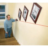
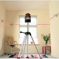
AUTO LEVELING LASER LINES
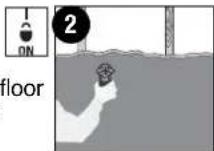
Operation of Laser: Place unit flat against wall as shown in Figure 2. Move laser on/off button (A) to unlock symbol (see inset) position to actuate the auto leveling laser lines.
LOCKED LASER LINES
Operation of Laser: Place unit flat against wall as shown in Figure
- Move laser on/off button (A) to lock symbol (see inset) position to activate the lasers while they are locked aligned with the reference surfaces of the unit. Locked laser lines can be used on a wall or on a floor surface. Unit has square reference edges for perpendicular laser line reference.
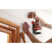
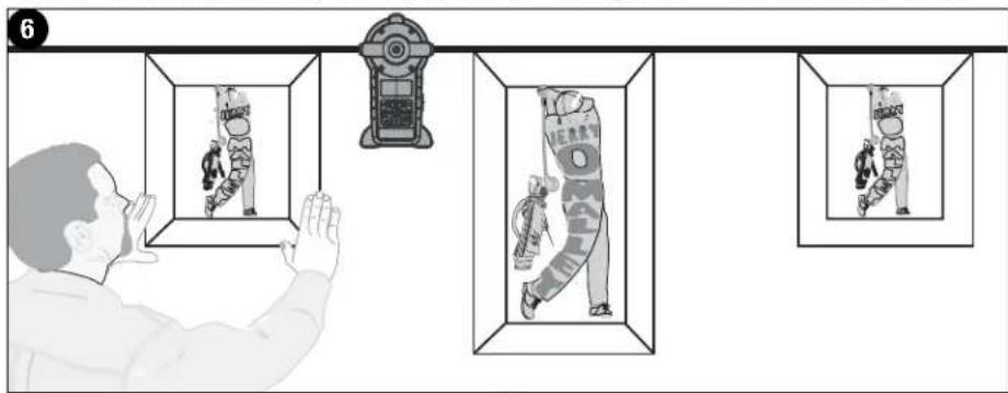
HANGING ON DRYWALL SURFACES ONLY
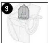
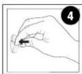
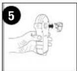
Hands Free Operation of Laser: To hang the unit on a wall, remove the orange protective cap from the drywall pin (J) and store it on the cone as shown in Figure 3. Push pin into drywall (Figure 4). When pressing pin into drywall, make sure it is straight and seated firmly. Hang the laser on the cone as shown in Figure 5 and check to make sure that the unit is secure on the wall. Figure 6 illustrates a typical application for the laser when it is wall mounted.
⚠️CAUTION: Pin is sharp and should be handled with care. The drywall pin should always be pushed in by hand and never driven by a hammer. Replace protective cap after each use.
NOTE: The pin is only for use on drywall NOT other surfaces including plaster.
HANGING ON OTHER SURFACES
Hands Free Operation of Laser: For surfaces other than drywall, the (key hole) hanging cone (I) can be used with a standard nail or screw in a predrilled hole. To use the keyhole hanging cone, place it over a nail or screw on a vertical surface with the narrow portion of the opening pointing upward. Push the laser onto the hanging cone until it snaps into place. To remove the laser, lift it slightly and pull it straight off. The unit can also be used
6
with the hanging cone attached to the back and then hanging the unit on the nail or screw. Make sure it is straight and seated firmly on the cone and that the unit is secure on the wall.
⚠️ DANGER: Laser Radiation, avoid direct eye exposure.
HELPFUL HINTS
- If the laser light becomes dim or is no longer visible when the switch is in the on position check or change the batteries.
- The laser lines are only level on the wall against which the unit is held or hung. The short line visible on any adjacent wall is not level.
- The unit can be used on a floor during locked laser mode.
- The laser unit is equipped with a pendulum lock that stops pendulum motion when the laser on/off switch is moved to the off position.
- If the laser on/off switch is pushed part way to the on position, the laser lines may be on while the pendulum lock is still engaged.
- When using unit over a stucco wall, place a piece of cardboard over the surface to help provide a smooth motion across the wall.
STORAGE
Always store the laser indoors in its protective case.
MAINTENANCE
Use only mild soap and damp cloth to clean the tool. Never let any liquid get inside the tool; never immerse any part of the tool into a liquid.
IMPORTANT: To assure product SAFETY and RELIABILITY, repairs, maintenance and adjustment (other than those listed in this manual) should be performed by authorized service centers or other qualified service personnel, always using identical replacement parts.
TROUBLESGOUNG
| Problem | Possible Cause | Solution |
| • Laser does not project on wall. | • Weak battery.• The self leveling range of the unit is ± 5 degrees, if the unit is not held within 5 degrees of vertical, the laser lines will not project on wall. | • Replace with fresh battery.• Be sure that the unit is as straight up and down as possible. |
| • Laser projects on wall but lines are not level. | • Wall on which the unit is mounted or held must be within ± 5 degrees of vertical for the self leveling mechanism to function correctly. If this is exceeded, the lines will still project but may not be level.• The laser on/off switch must be pushed to the full on position. | • Use the unit against vertical walls only, lines will not be level on sloped walls or other non-vertical surfaces.• Be sure laser on/off switch is in the full on position. |
ACCESSORIES
Recommended accessories for use with your tool are available from your local dealer or authorized service center. If you need assistance regarding accessories, please call:
1-800-54-HOW-TO (544-6986).
WARNING: The use of any accessory not recommended for use with this tool could be hazardous.
All Black & Decker Service Centers are staffed with trained personnel to provide customers with efficient and reliable power tool service. Whether you need technical advice, repair, or genuine factory replacement parts, contact the Black & Decker location nearest you. To find your local service location, refer to the yellow page directory under "Tools—Electric" or call: 1-800-544-6986 or visit www.blackanddecker.com
FULL TWO-YEAR HOME USE WARRANTY
Black & Decker (U.S.) Inc. warrants this product for two years against any defects in material or workmanship. The defective product will be replaced or repaired at no charge in either of two ways.
The first, which will result in exchanges only, is to return the product to the retailer from whom it was purchased (provided that the store is a participating retailer). Returns should be made within the time period of the retailer's policy for exchanges (usually 30 to 90 days after the sale). Proof of purchase may be required. Please check with the retailer for their specific return policy regarding returns that are beyond the time set for exchanges.
The second option is to take or send the product (prepaid) to a Black & Decker owned or authorized Service Center for repair or replacement at our option. Proof of purchase may be required. Black & Decker owned and authorized Service Centers are listed under "Tools-Electric" in the yellow pages of the phone directory and on our website www.blackanddecker.com.
This warranty does not apply to accessories. This warranty gives you specific legal rights and you may have other rights which vary from state to state. Should you have any questions, contact the manager of your nearest Black & Decker Service Center. This product is not intended for commercial use.
FREE WARNING LABEL REPLACEMENT: If your warning labels become illegible or are missing, call 1-800-544-6986 for a free replacement.
Imported by
Black & Decker (U.S.) Inc.,
701 E. Joppa Rd.
Towson, MD 21286 U.S.A.

See 'Tools-Electric'
- Yellow Pages –
for Service & Sales

TECHNICAL SPECIFICATIONS OF LASER LEVEL:
Laser Diode Wavelength: 635 ± 5 nm (red color)
Laser Class: Class IIIa
Working Range: Up to 20 feet (609 cm) (depends on light conditions)
Leveling Accuracy: ±1/8 inch (3 mm) @ 10 feet (3 m)
Auto Leveling Range: ±5°
Measurement Accuracy: +/- 1/16" (1.59 mm) within 10 feet (3 m)
Auto Leveling Lines Settling Time: <5 sec
Batteries: 3 AAAlkaline (included)
Voltage: 4.5 Volt
Operating Temperature: 41°F (5°C) - 104°F (40°C)

BLACK & DECKER®
BDL500S LASERR
MODE D'EMPLOI
AVANT DE RETOURNER CE PRODUIT POUR QUELQUE
RAISON QUI SOIT, VEUILLEZ APPELER AU
1-800-54-HOW-TO (544-6986)
CARACTÉRISTIQUES
natural_image
Pure technical diagram of a mechanical or electrical component without any text, numbers, or symbols
Pose de la pile
ACCROCHAGE DE L'OUTIL SUR D'AUTRES SURFACES
Black & Decker Canada Inc.
100 Central Ave.
ANTES DE DEVOLVER ESTE PRODUCTO POR CUALQUIER RAZON, POR FAVOR LLAME AL (55)5326-7100
CARACTERÍSTICAS
natural_image
Pure technical diagram of a mechanical or electrical component with no text, numbers, or symbols
Col. Industrial Bravo
GUADALAJARA, JAL
Av. La Paz #1779
(33) 3825 6978
Col. Americana Sector Juarez
MEXICO, D.F.
Local D, Col. Obrera
MERIDA, YUC
Calle 63 #459-A
(999) 928 5038
Col. Centro
MONTERREY, N.L.
Cat No. BDL500S Form #489469-00 JULY-05 Copyright © 2005 Black & Decker Printed in China