DW866 - Saw DEWALT - Free user manual and instructions
Find the device manual for free DW866 DEWALT in PDF.

User questions about DW866 DEWALT
0 question about this device. Answer the ones you know or ask your own.
Ask a new question about this device
Download the instructions for your Saw in PDF format for free! Find your manual DW866 - DEWALT and take your electronic device back in hand. On this page are published all the documents necessary for the use of your device. DW866 by DEWALT.
USER MANUAL DW866 DEWALT
384621-01/DW866 1/8/02 2:27 PM Page 2
DeWALT Industrial Tool Co., 701 East Joppa Road, Baltimore, MD 21286
DW866 Copyright © 1998
Printed in U.S.A. (JUN98-CD-1) Form No. 384621-01
INSTRUCTION MANUAL GUIDE D'UTILISATIONMANUAL DE INSTRUCCIONES
DEWALT®
DW866
12" (105mm) Cut-off Machine
IF YOU HAVE ANY QUESTIONS OR COMMENTS ABOUT THIS OR ANY DEWALT TOOL, CALL US TOLL FREE AT:
1-800-4-Dewalt(1-800-433-9258)
General Safety Rules
WARNING! Read and understand all instructions. Failure to follow all instructions listed below may result in electric shock, fire and/or serious personal injury.
SAVE THESE INSTRUCTIONS
WARNING: Improper connection of the equipment grounding conductor can result in the risk of electric shock. Check with a qualified electrician or service person if you are in doubt as to whether the outlet is properly grounded. Do not modify the plug provided with the appliance. If it will not fit the outlet, a proper outlet must be installed by a qualified electrician.
We recommend that you never disassemble the tool or try to do any rewiring in the electrical system. Any repairs should be performed only by authorized service centers. Should you be determined to make a repair yourself, remember that the green colored wire is the grounding wire. Never connect this green wire to a live terminal. If you replace the plug on the power cord, be sure to connect the green wire only to the grounding (longest) prong on a three-prong plug. Never remove the grounding prong.
WORK AREA
- Keep your work area clean and well lit. Cluttered benches and dark areas invite accidents.
- Do not operate power tools in explosive atmospheres, such as in the presence of flammable liquids, gases, or dust. Power tools create sparks which may ignite the dust or fumes.
- Keep bystanders, children, and visitors away while operating a power tool. Distractions can cause you to lose control.
ELECTRICAL SAFETY
- Grounded tools must be plugged into an outlet properly installed and grounded in accordance with all codes and ordinances. Never remove the grounding prong or modify the plug in any way. Do not use any adapter plugs. Check with a qualified electrician if you are in doubt as to whether the outlet is properly grounded. If the tools should electrically malfunction or break down, grounding provides a low resistance path to carry electricity away from the user.
- Double insulated tools are equipped with a polarized plug (one blade is wider than the other.) This plug will fit in a polarized outlet only one way. If the plug does not fit fully in the outlet, reverse the plug. If it still does not fit, contact a qualified electrician to install a polarized outlet. Do not change the plug in any way. Double insulation eliminates the need for the three wire grounded power cord and grounded power supply system.
- Avoid body contact with grounded surfaces such as pipes, radiators, ranges and refrigerators. There is an increased risk of electric shock if your body is grounded.
- Don't expose power tools to rain or wet conditions. Water entering a power tool will increase the risk of electric shock.
- Do not abuse the cord. Never use the cord to carry the tools or pull the plug from an outlet. Keep cord away from heat, oil, sharp edges or moving parts. Replace damaged cords immediately. Damaged cords increase the risk of electric shock.
- When operating a power tool outside, use an outdoor extension cord marked "W-A" or "W." These cords are rated for outdoor use and reduce the risk of electric shock. When using an extension cord, be sure to use one heavy enough to carry the current your product will draw. An undersized cord will cause a drop in line voltage resulting in loss of power and overheating. The following table shows the correct size to use depending on cord length and nameplate ampere rating. If in doubt, use the next heavier gage. The smaller the gage number, the heavier the cord.
Minimum Gage for Cord Sets
Volts Total Length of Cord in Feet
120V 0-25 26-50 51-100 101-150
240V 0-50 51-100 101-200 201-300
| Ampere Rating | |||||||
| More | Not | more | AWG | ||||
| Than | Than | ||||||
| 0 | - | 6 | 1 | 8 | 1 | 6 | |
| 6 | - | 10 | 18 | 14 | 12 | ||
| 1 | 0 | - | 1 | 2 | 6 | 1 | 6 |
| 12 | - | 16 | 14 | 12 | Not Recommended | ||
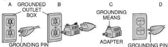
Grounding
This tool should be grounded while in use to protect the operator from electric shock. The tool is equipped with an approved three-conductor cord and three-prong grounding type plug to fit the proper grounding type receptacle. The green (or green and yellow) conductor in the cord is the grounding wire. Never connect the green (or green and yellow wire to a live terminal.
If your unit is intended for use on less than 150 volts, it has a plug similar to that shown in Figure A. An adapter, Figures B and C, is available for connecting Figure A plugs to two-prong receptacles. The green-colored rigid ear, lug, etc., must be connected to a permanent ground such as a properly grounded outlet box. Whenever the adapter is used, it must be held in place by a metal screw.
ADAPTER SHOWN IN FIGURES B and C IS NOT FOR USE IN CANADA.
PERSONAL SAFETY
- Stay alert, watch what you are doing and use common sense when operating a power tool. Do not use tool while tired or under the influence of drugs, alcohol, or medication. A moment of inattention while operating power tools may result in serious personal injury.
- Dress properly. Do not wear loose clothing or jewelry. Contain
long hair. Keep your hair, clothing, and gloves away from moving parts. Loose clothing, jewelry, or long hair can be caught in moving parts. - Avoid accidental starting. Be sure switch is off before plugging in. Carrying tools with your finger on the switch or plugging in tools that have the switch on invites accidents.
- Remove adjusting keys or wrenches before turning the tool on. A wrench or key that is left attached to a rotating part of the tool may result in personal injury.
- Do not overreach. Keep proper footing and balance at all times. Proper footing and balance enables better control of the tool in unexpected situations.
- Use safety equipment. Always wear eye protection. Dust mask, non-skid safety shoes, hard hat, or hearing protection must be used for appropriate conditions.
The label on your tool may include the following symbols.
V. volts
A. amperes
Hz hertz
W.....watts
min.. minutes
...alternating current
direct current
no.. no load speed
Class II Construction
384621-01/DW866 1/8/02 2:27 PM Page 2
English
...min . . . . . . . . . . . . . . . . . . . . . . . . . . . . . . . . . . . . . . . . . . . . . . . . revolutions or reciprocation per minute
...earthing terminals
..safety alert symbol
TOOL USE AND CARE
- Use clamps or other practical way to secure and support the workpiece to a stable platform. Holding the work by hand or against your body is unstable and may lead to loss of control.
- Do not force tool. Use the correct tool for your application. The correct tool will do the job better and safer at the rate for which it is designed.
- Do not use tool if switch does not turn it on or off. Any tool that cannot be controlled with the switch is dangerous and must be repaired.
- Disconnect the plug from the power source before making any adjustments, changing accessories, or storing the tool. Such preventative safety measures reduce the risk of starting the tool accidentally.
- Store idle tools out of reach of children and other untrained persons. Tools are dangerous in the hands of untrained users.
- Maintain tools with care. Keep cutting tools sharp and clean.
- Properly maintained tools, with sharp cutting edges are less likely to bind and are easier to control.
- Check for misalignment or binding of moving parts, breakage of parts, and any other condition that may affect the tools operation. If damaged, have the tool serviced before using. Many accidents are caused by poorly maintained tools.
- Use only accessories that are recommended by the manufacturer for your model. Accessories that may be suitable for one tool, may become hazardous when used on another tool.
SERVICE
- Tool service must be performed only by qualified repair personnel. Service or maintenance performed by unqualified personnel could result in a risk of injury.
- When servicing a tool, use only identical replacement parts. Follow instructions in the Maintenance section of this manual. Use of unauthorized parts or failure to follow Maintenance Instructions may create a risk of electric shock or injury.
Additional Safety Instructions for Cut-Off Machine
CAUTION: When cutting into walls, floors or wherever live electrical wires may be encountered, DO NOT TOUCH ANY METAL PARTS OF THE TOOL! Hold the tool only by insulated grasping surfaces to prevent electric shock if you cut into a live wire.
- ALWAYS WEAR EYE PROTECTION WHEN USING THIS TOOL.
- Use of accessories not specified in this manual is not
recommended and may be hazardous. Use of power boosters that would cause the tool to be driven at speeds greater than its rated speed constitutes misuse.
- Before attaching any wheel, check its manufacturer's specifications and be sure that its safe operating speed is higher than the no-load speed of the tool as shown on the nameplate.
- Before using, inspect each grinding wheel for cracks or flaws. If such a crack or flaw is evident, discard the wheel. The wheel should also be inspected whenever you think the tool may have been dropped. Do not set unit down on wheel.
- When starting the tool (with a new or replacement wheel installed) hold the tool in a well protected area. Never start the tool with a person in line with the wheel. This includes the operator.
- In operation, avoid bouncing the wheel or giving it rough treatment. If this occurs, stop the tool and inspect the wheel.
Clean your tool out periodically.
- Protect personnel and combustible material in work area from sparks generated by this tool.
SAVE THESE INSTRUCTIONS
Motor
Be sure your power supply agrees with the nameplate marking. Voltage decrease of more than 10% will cause loss of power and overheating. All D=Walt tools are factory tested; if this tool does not operate, check the power supply.
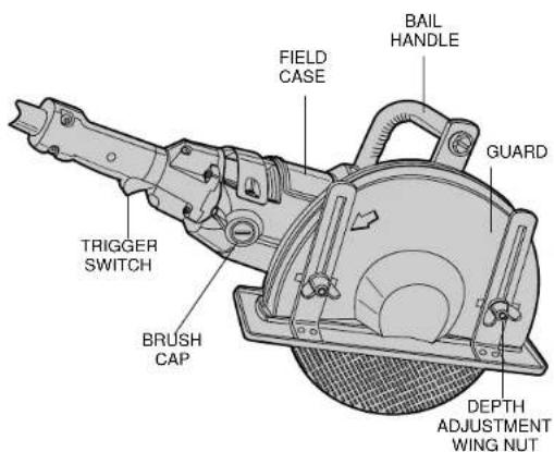
Controls (Figures 1 and 2)
CAUTION: Grasp tool firmly with both hands before attempting to start. To start, grasp switch handle firmly and squeeze to depress trigger. To stop tool, release trigger.
GUARD ADJUSTMENT: Disconnect tool from power supply and be sure switch is in off position before adjusting guard. Guard may be adjusted approximately 80^ by loosening the guard adjustment knob.
Grasp the guard firmly and rotate to desired angle. Lock in position by tightening the guard adjustment knob.
NOTE: The two guard mounting screws on each end of the clamp should not be over-tightened, in order to allow the guard to rotate.
SPINDLE LOCK PIN is used to lock the spindle when changing accessories. To engage the lock pin, disconnect the tool from the power supply and be sure switch is in off position. Depress the lock pin and turn the wheel and spindle until the lock pin engages the spindle. Use wrench, supplied with the unit, to unscrew the spindle nut and remove or mount accessories. Spindle and nut have right hand threads.
NOTE: Slot in wrench handle may be used for additional leverage when tightening or loosening wing nuts. Wrench is a standard part furnished with the unit. Shoe can be adjusted to give a 4^ maximum depth of cut.
Operation
- The tool is supplied with a cord and a 3-prong plug. Compare voltage marked on nameplate of tool with that of your power supply before plugging in tool. The voltages must be the same.
- Before turning on tool, grasp both handles firmly and pick up tool. Make sure nothing is near or in line with the wheel. Line up wheel with material to be cut.
- Turn on unit and feed wheel into work slowly, but with firm pressure, while keeping the shoe firmly and squarely against the work. Don not force the tool. For maximum efficiency and wheel life, keep the wheel speed high.
Depth of Cut
The depth of cut can be adjusted by loosening the two wing nuts on the outside of the guard. NOTE: The slot in handle of included wrench may be used for additional leverage when loosening or tightening the wing nuts.

TO CUT METALS AND THIN MATERIALS
For minimum operator effort and greatest efficiency when cutting metals and other thin materials, adjust shoe for maximum depth of cut (Figure 3).
TO CUT STONE OR MASONRY MATERIALS
For maximum effectiveness, set the wheel exposure to about 1 / 2^n (13mm) beyond the shoe. For many applications, the material will readily break along the 1 / 2^n (13mm) deep scored line. If a deeper cut is needed, increase the depth of cut in approximately 1 / 2^n (13mm) increments. See Figure 4.
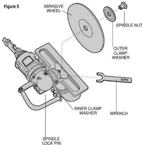
Installing Abrasive Wheels (Figure 5)
1. TURN OFF TOOL AND DISCONNECT FROM POWER SUPPLY.
- Lay unit on a firm surface with bottom of shoe facing up.
- Loosen shoe adjustment wing nuts, bring shoe up to minimum cutting depth and tighten wing nuts. This step allows more freedom in removing spindle nut and washers.
- Using 11 / 8^ (28mm) open end wrench (supplied with unit) remove spindle nut, outer clamp washer and used wheel if one is installed. Hold spindle from turning with spindle lock pin. Spindle threads are right hand.
- Select proper wheel, use only those approved accessories specified in this manual. Never use wheels rated lower than nameplate speed of unit.
- Make sure inner clamp washer is in place and ears are engaged with spindle flats. Slip wheel through bottom of shoe and slip wheel over spindle. Be sure wheel goes over pilot diameter, of inner clamp washer. Slip on outer clamp washer. Start threading on spindle nut which will self align outer clamp washer. Engage spindle lock pin and tighten nut with wrench. Do not over tighten spindle nut.
- Turn wheel by hand to make sure the wheel is properly centered, that the wheel does not hit the shoe or guard and nut and that nut and flanges are tight.
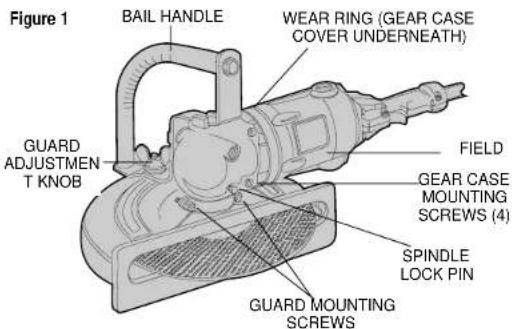
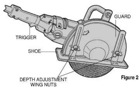
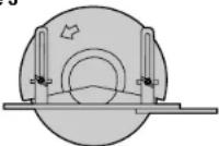
Figure 3
YES
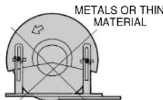
NO
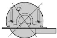
Figure 4
NO
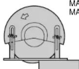
YES
Applications
1/8" (3mm) max. gauge sheet metal
concrete, cinder blocks and bricks
reinforcing rod- generally under 3 / 4'' (19mm) diameter
1/8"(3mm) diameter concrete wire mesh
corrugated floor and ceiling form (concrete forms)
electrical conduit 1 / 8" (3mm) wall thickness
1/8" (3mm) max. thick structural forms such as channel, angles, plate, etc.
NOTE: The cutting of materials heavier than those listed above are not recommended due to the possibility of electrical overloading.
Conversion From Right Handed to Left Handed
Operation
NOTE: This machine is assembled at the factory with the spindle on right side of the unit for right handed operation.
1. TURN OFF TOOL AND DISCONNECT FROM POWER SUPPLY.
2. Place unit on a firm, flat work surface.
3. Remove brush caps and brushes
4. Remove bail handle by removing guard adjusting knob and hex bolt.
5. Remove the 4 gear case mounting screws.
6. Remove gear case.
7. Remove wear ring.
8. Pry the gear case cover, with armature attached, from field case. The armature and gear case cover are one subassembly.
9. IMPORTANT: Notice a flat tab projecting from the gear case cover and a corresponding recess in the gear case opposite the spindle. Line up these two features and reassemble the gear case and cover.
10. Replace the wear ring on the field case.
11. Rotate the field case and switch handle assembly 180^ . Then, when viewing from the cord end, with the trigger switch down, the spindle should be on the left side of the unit.
12. Replace the 4 gear case mounting screws.
13. Rotate the guard until the shoe faces in the same direction as the switch guard. Be sure the guard is on the spindle bearing hub as far as it will go and tighten guard mounting screws.
14. Replace the bail handle with the bolt and the guard adjusting knob.
15. Replace brushes and brush caps.
Accessories
Recommended accessories for use with your tool are available at extra cost from your distributor or authorized service center.
English
CAUTION: The use of any non-recommended accessory may be hazardous.
Accessory Maximum Safe Speed
Masonry Wheel* 6300 RPM
(Silicon Carbide) 12" Dia. x 1/8" Thick x 1" Hole
Metal Cutting Wheel* 6300 RPM
(Aluminum Oxide) 12" Dia. x 1/8" Thick x 1" Hole
*Internally Reinforced
Cleaning
Blowing dust and grit out of the main housing by means of an air hose is recommended and may be done as often as dirt is seen collecting in and around the air vents. The motor should be running while air is being blown into the vents.
Lubrication
Except for the needle roller bearings used at the upper end of the spindle, closed-type, grease-sealed ball bearings are used throughout. These bearings have sufficient lubrication packed in them at the factory to last the life of the bearing. The needle bearings mentioned above receive their lubrication from the grease in the gear case.
Gears should be relubricated every 60 to 90 days, depending upon use. This lubrication should only be attempted by experienced power tool repair technicians like the mechanics at B&D service centers.
Brushes
Inspect carbon brushes often. Replace when brushes are worn down to the identifying groove or when spring exerts insufficient pressure to hold brush against commutator. Keep brushes clean and sliding free in brass inserts.
TO REMOVE BRUSHES:
-
TURN OFF TOOL AND DISCONNECT FROM POWER SUPPLY.
-
Remove brush cap.
- Pull brush assembly out of brass insert.
Motor Brushes
DeWALT uses an advanced brush system which automatically stops the drill when the brushes wear out. This prevents serious damage to the motor.
Maintenance
Use only mild soap and damp cloth to clean the tool. Never let any liquid get inside the tool; never immerse any part of the tool into a liquid.
Self-lubricating bearings are used in the tool and periodic relubrication is not required. In the unlikely event that service is ever needed, take your tool to an authorized service location.
Accessories
Recommended accessories for use with your tool are available at extra cost from your distributor or local service center.
ACCESSORY MUST BE RATED FOR USE AT SPEED EQUAL TO OR HIGHER THAN NAMEPLATE R.P.M. OF TOOL WITH WHICH IT IS BEING USED.
If you need assistance in locating any accessory, please contact DeWALT Industrial Tool Company, 626 Hanover Pike, P.O. Box 158, Hampstead, MD 21074 or call 1-800-4-DeWALT (1-800-732-4441).
CAUTION: The use of any non-recommended accessory may be hazardous.
Important
To assure product SAFETY and RELIABILITY, repairs, maintenance and adjustment (including brush inspection and replacement) should be performed by authorized service centers or other qualified service organizations, always using identical replacement parts.
Full Warranty
DeWALT heavy duty industrial tools are warranted for one year from date of purchase. We will repair, without charge, any defects due to faulty materials or workmanship. For warranty repair information, call 1-800-4-DeWALT. This warranty does not apply to accessories or damage caused where repairs have been made or attempted by others. This warranty gives you specific legal rights and you may have other rights which vary in certain states or provinces.
In addition to the warranty, DeWALT tools are covered by our:
30 DAY NO RISK SATISFACTION GUARANTEE
If you are not completely satisfied with the performance of your DeWALT heavy duty industrial tool, simply return it to the participating seller within 30 days for a full refund. Please return the complete unit, transportation prepaid. Proof of purchase may be required.
BOSQUES DE CIDROS ACCESO RADIATAS NO.42
COL.BOSQUES DE LAS LOMAS 02000V98.75
T20 MEXICO, LTELLO 700-7160
Para增值服务ventas consulte
TRAMIENTAS ELECTRIC