
TP 12000 SI - Pump METABO - Free user manual and instructions
Find the device manual for free TP 12000 SI METABO in PDF.
| Product type | Submersible pump |
| Brand | Metabo |
| Model | TP 12000 SI |
| Mains voltage | 230 V ~ 1 |
| Frequency | 50 Hz |
| Rated power | 600 W |
| Rated current | 2.5 A |
| Max. flow rate | 11,700 l/h |
| Max. delivery head | 9 m |
| Max. discharge pressure | 0.9 bar |
| Max. immersion depth | 7 m |
| Max. residual water level | 3 mm |
| Max. feed temperature | 35 °C |
| Protection rating | IP 68 |
| Protection class | I |
| Insulation class | B |
| Housing material | Polypropylene |
| Pump shaft material | Stainless steel |
| Impeller material | Noryl |
| Power cable | 10 m, type H05 RN-F |
| Pressure connection | 1 1/4" male |
| Dimensions (housing) - Height | 320 mm |
| Dimensions (housing) - Width | 190 mm |
| Dimensions (housing) - Diameter | 230 mm |
| Weight | 5.1 kg |
| Max. extension cable length (cross-section 3x1.0 mm²) | 60 m |
| Max. extension cable length (cross-section 3x1.5 mm²) | 100 m |
| Operating modes | Automatic (float switch) and manual |
| Application | Draining tanks, wells, flooded rooms; water circulation; water supply for streams |
| Pumped liquids | Clear water, rainwater, chlorinated pool water (max. 35°C) |
| Maintenance | Rinse with clean water after use; clean float and base |
| Safety | 30 mA residual current device; dry-run protection; do not use for drinking water |
| Repairs | Entrust to a Metabo professional; identical spare parts |
Frequently Asked Questions - TP 12000 SI METABO
User questions about TP 12000 SI METABO
0 question about this device. Answer the ones you know or ask your own.
Ask a new question about this device
Download the instructions for your Pump in PDF format for free! Find your manual TP 12000 SI - METABO and take your electronic device back in hand. On this page are published all the documents necessary for the use of your device. TP 12000 SI by METABO.
USER MANUAL TP 12000 SI METABO
natural_image
Technical line drawing of a mechanical component with threaded ports and internal structure (no text or symbols)
(D) Originalbetriebsanleitung 3
ENG Original operating instructions 9
(F) Instructions d'utilisation originales ..... 14
NL Origineel gebruik aanwijzing 20
① Original brugsvejledning 26
① Πρωτότυπο οδηγιών λειτουργίας 32
SLO Izvirna navodila za uporabo 38
FIN Alkuperäiskäyttöohje 44
RUS Оригинальное руководство по эксплуатации 49
| de Deutsch KONFORMITÄTSERKLÄRUNGWir erklären in alleiniger Verantwortlichkeit: Diese Klarwasser-Tauchpumpe,identifiziert durch Type und Seriennummer *1), entspricht allen einschlägigen Bestimmungen der Richtlinien *2)und Normen *3). Technische Unterlagen bei *4) - siehe unten. |
| en English DECLARATION OF CONFORMITYWe declare under our sole responsibility: This clear water immersion pump,identified by type and serial number *1), complies with all relevant requirements of the directives *2)and standards *3). Technical file at *4) - see below. |
| fr Français DÉCLARATION DE CONFORMITÉNous déclarons sous notre seule responsabilité : Cette pompe immergées pour eaux claires, identifiée par le typeet le numéro de série *1), est conforme à toutes les prescriptions applicables des directives *2) et normes *3).Documents techniques pour *4) - voir ci-dessous. |
| nl Nederlands CONFORMITEITSVERKLARINGWij verklaren op eigen en uitsluitende verantwoording: Deze schoonwaterdompomp, geïdentificeerd door typeen serienummer *1), voldoet aan alle relevante bepalingen van de richtlijnen *2) en normen *3).Technische documentatie bij *4) - zie onder. |
| da Dansk OVERENSSTEMMELSESERKLÆRINGVi erklærer under almindeligt ansvar: Denne rentvands-dykpumpe, identificeret ved angivelse af typeog serienummer *1), opfylder alle relevante bestemmelser i direktiverne *2) og standarderne *3).Teknisk dossier ved *4) - se nedenfor. |
| es Español DECLARACIÓN DE CONFORMIDADDeclaramos con responsabilidad propia: Esta bomba sumergible para agua limpia, identificada por tipo ynúmero de serie *1), corresponde a las disposiciones correspondientes de las directivas *2) y de las normas *3).Documentación técnica con *4) - ver abajo. |
| el Ελληνικά ΔΗΛΩΣΗ ΠΙΣΤΟΤΗΤΑΣΔηλώνουμε με ιδία ευθύνη: Αυτή η Βυθιζόμενη αντλία καθαρού νερού, που αναγνωρίζεται μέσω τύπου και αριθμούσειράς *1), ανταποκρίνεται σε όλες τις σχετικές διατάξεις των οδηγιών *2) και των προτύπων *3).Τεχνικά έγγραφα στο *4) - βλέπε κατωτέρω. |
| fi Suomi VAATIMUSTENMUKAISUUSVAKUUTUSVakuutamme yksinomaisella vastuullamme: Tämä puhtaan veden uppopumppu, merkitty tyyppitunnuksella jasarjanumerolla *1), vastaa direktiivien *2) ja normien *3)kaikkia asiaankuuluvia määräyksiä. Teknisten asiakirjojen säilytyspaikka *4) - katso alhaalla. |
*1) TP 7500 SI - 02507500... ; TP 12000 SI - 02512000...
*2) 2011/65/EU 2006/95/EC 2004/108/EC
*3) EN 50581 EN 60335-1 EN 60335-2-41 EN 62233
EN 55014-1: EN 55014-2 EN 61000-3-2 EN 61000-3-3

2015-02-06, Volker Siegle
(Director Innovation, Research and Development)
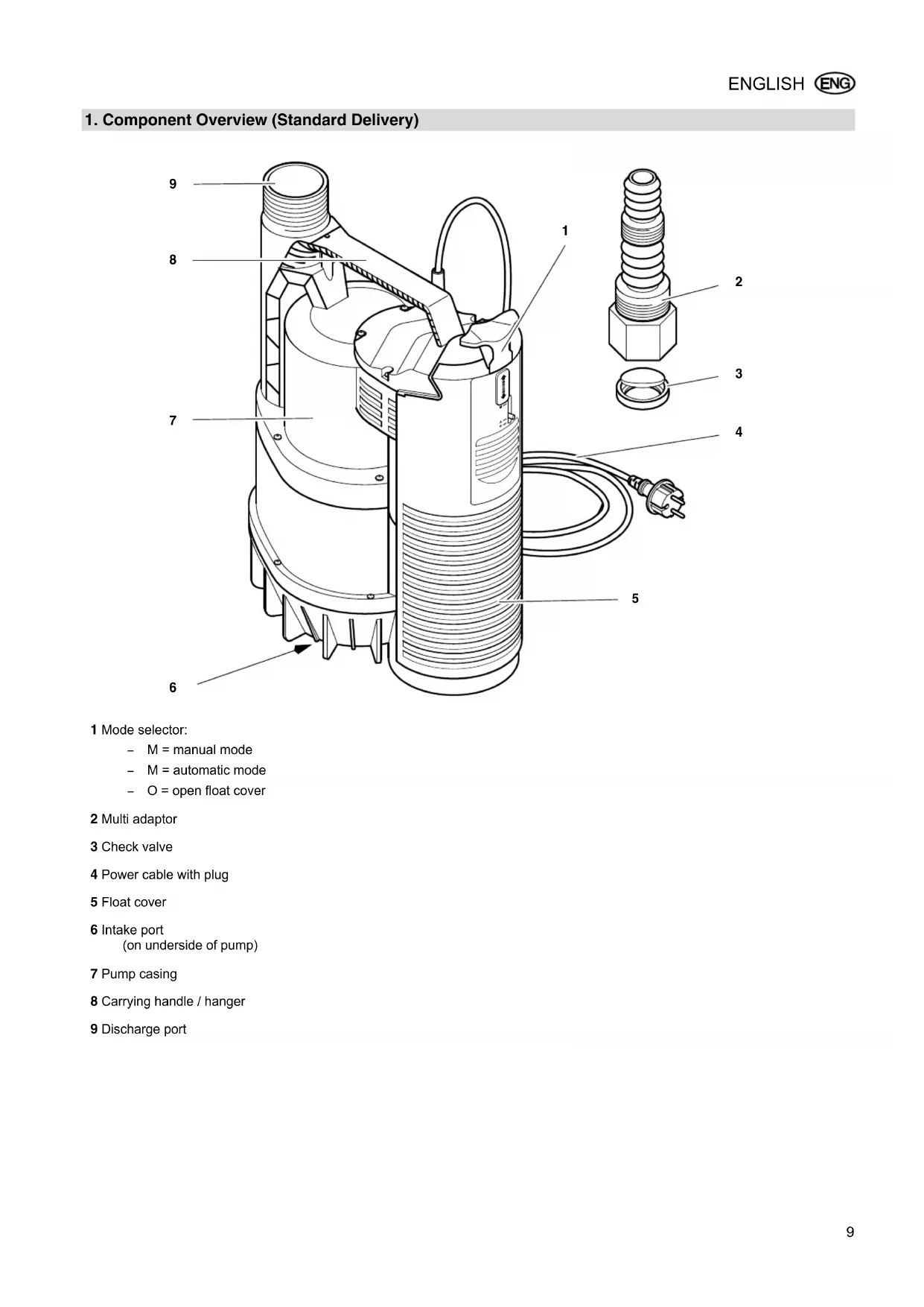
1 Bedienschieber:
natural_image
Technical diagram of a mechanical component with threaded fasteners and a circular base, labeled '20' (no text or symbols beyond label)1 Mode selector:
- M = manual mode
- M = automatic mode
- O = open float cover
2 Multi adaptor
3 Check valve
4 Power cable with plug
5 Float cover
6 Intake port
(on underside of pump)
7 Pump casing
8 Carrying handle / hanger
9 Discharge port
Table of Contents
-
Component Overview (Standard Delivery) .....9
-
Please Read First!......10
-
Range of Application and Pumping Media ....10
-
Safety ......10
4.1 Specified conditions of use .....10
4.2 General safety information .....10
- Prior to Operation ......11
5.1 Discharge hose connection.....11
5.2 Installation....11
- Operation ......12
6.1 Automatic mode ..... 12
6.2 Manual mode ......12
- Care and Maintenance......12
7.1 Periodic maintenance.....12
7.2 Pump storage....12
- Trouble Shooting .....12
8.1 Fault finding....13
-
Repairs......13
-
Environmental Protection .....13
-
Technical Specifications .....13
2. Please Read First!
These instructions are written in a way that will enable you to safely use the machine in a minimum of time. Here is how to read the instructions:
- Read these instructions completely before use. Pay special attention to the safety information.
- These instructions are intended for persons having a basic technical knowledge in the handling of machines such as the one described here. If you have no experience with this type of machine you are advised to seek the advise of an experienced individual before operating this machine.
- Keep all documents supplied with the machine for future reference. Retain proof of purchase for possible warranty claims.
- If you hire out or sell this machine be sure to hand over the machine documents supplied.
- The equipment manufacturer is not liable for any damage arising from disregard of these instructions.
The information in these instructions is denoted as under:

Danger! Warning of personal injury or environmental damage.
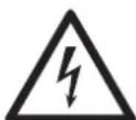
Risk of electric shock! Risk of personal injury by electric shock.

Caution!
Risk of material damage

Note:
Supplementary information.
- Numbers in illustrations (1, 2, 3, ...)
– indicate component parts;
– are consecutively numbered;
– refer to the corresponding numbers in brackets (1), (2), (3) ... in the neighbouring text.
– Instructions to be carried out in sequence are numbered.
- Instructions which can be carried out in any sequence are preceded by a bullet (•).
– Listing are preceded by a M-dash (−).
3. Range of Application and Pumping Media
This pump is intended for pumping water in domestic applications, such as
- pumping containers, sumps and flooded basements;
- fountain pumps;
– circulation to avoid putrefaction;
– feeding false rivulets and brooks.

Caution!
The max. permissible fluid temperature is 35 °C.
Pumping liquids containing abrasives (such as sand) reduces the service life of the pump.
4. Safety
4.1 Specified conditions of use
This pump must not be used to supply drinking water or for pumping foodstuff.
Explosive, flammable, aggressive fluids or substances detrimental to health, sewage must not be pumped.
This pump is not suitable for commercial or industrial use.
Any other use is not as specified. Use not as specified, alteration of the machine or use of parts that are not approved by the equipment manufacturer, can cause unforeseeable damage!
4.2 General safety information
This device is not designed for use by persons (including children) with physical, sensory or mental disabilities, or with insufficient experience and/or knowledge, unless they are supervised by a person responsible for their safety, or have received instructions on how to use the device by this person.
Never allow children to use the machine.
Children should be supervised to ensure that they do not play with the tool.
When used in swimming pools and garden ponds and their range of protection, the regulations according to DIN VDE 0100 -702, -738 are to be observed.
Also all local regulations pertaining to the safe operation of submersible pumps must be followed.
The following residual risks do principally exist when operating submersible pumps and can not be fully eliminated – even by employing safety devices.

Hazard by ambient con- ns!
Do not use the pump in hazardous locations or near inflammable liquids and gases!

Danger: Hot water!
If the shut-off pressure of the pressure switch cannot be reached due to poor pressure conditions or a defective pressure switch the water can heat up within the pump as a result of internal circulation.
Through this the pump and the connection lines can become damaged or leaky, allowing hot water to escape. Danger of scalding!
- Do not operate the pump against a closed pressure line for longer than 5 minutes.
- Unplug the pump and allow to cool. A specialist must check the system to make sure it is in perfect working order before it can be used again.
Danger! Risk of electric shock!
- Do not touch the plug with wet hands! To unplug always pull at the plug, not the power cable.
- Connect only to an earthed outlet that is properly installed, earthed and tested. Mains voltage and fuse protection must correspond to those stated in the "Technical Specifications".
- Protection must be provided by a residual current device (RCD) of max. 30 mA capacity.
- The earthed outlet or the plug connection to an extension cable must be located in an area safe against flooding.
- Use only extension cables of sufficient lead cross section (see "Technical Specifications"). Unroll cable reels fully.
- Do not buckle, squeeze, drag or drive over power cable and extension cables; protect from sharp edges.
- Place extension cable so that it can not get into the fluid to be pumped.
- Unplug: - prior to all servicing; - when persons are in the swimming pool or garden pond.
⚠️ Danger by pump failures!
- If you notice shipping damage while unpacking, notify your supplier immediately. Do not operate the machine!
- Before each use check the pump, especially the power cable and plug for possible
damage. Risk of fatal elec- tric shock!
- A damaged pump must be workmanlike repaired before it can be used again.
- Do not attempt to repair the pump yourself! When repaired inexpertly there is a hazard of fluid entering the electrical parts of the pump.

Caution!
To avoid water damage, e.g. flooded rooms, caused by pump malfunctions or defects:
• provide for suitable safety measures such as the following:
- alarm or
– collection tank with monitoring.
The manufacturer is not liable for any damage caused by:
– improper use of the pump;
– overloading of the pump through continuous operation;
– failure to operate and store the pump in a frost-free environment;
- unauthorised modification of the pump (repairs to electrical equipment may only be carried out by qualified electricians!);
- use of spare parts which have not been tested and approved by the manufacturer; or
- use of unsuitable installation materials (fittings, connection lines etc.).
Suitable installation materials:
- pressure-resistant (min. 10 bar)
- heat-resistant (min. 100°C).
5. Prior to Operation
5.1 Discharge hose connection
The discharge hose is connected either directly to the discharge port (10), or by means of the multi-adapter (11) (secure
discharge hose with hose clamps, if necessary).
The check valve's flap (12) must open in the direction indicated by the arrow. (The marking "UP" must face the multi adaptor).
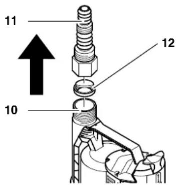

Note:
When using the multi adaptor cut off any parts nor required, as they reduce the flow unnecessarily.
5.2 Installation
• Space required approx. 20 cm x 20 cm.
- The pump must not be submerged deeper into water then stated in the "Technical Specifications".
- Place pump so that the suction inlet can not be blocked by foreign objects (stand on a base, if necessary).
- Ensure sufficient upright stability.

Caution!
Do not lift pump at cable or discharge hose; both are not designed for the tensile load by the weight of the pump.
- Lower pump to the bottom of the fluid container. Use a strong rope, fastened to the handle/hanger to lower the pump.
The pump can also be operated when suspended by a rope.
Any possibly present air cushion in the pump can escape through vent holes when the pump is lowered into the fluid. Venting generates air bubbles. This is no fault of the pump but the effect of automatic venting.
When using the pump for the first time it may take several seconds before the air is vented.
- To start the submersible pump plug power cable in.
- Unplug to stop the pump.
6. Operation
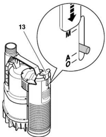
Before plugging in set the operating mode with the Mode selector (13):
Position A = Automatic mode
Position M = Manual mode
6.1 Automatic mode
In Automatic mode the submersible pump is automatically started and stopped by the integrated float switch:
- The pump starts pumping when the float switch is raised by the fluid above the starting level (14).
- The pump stops when float switch falls to below the cut-out level (15).
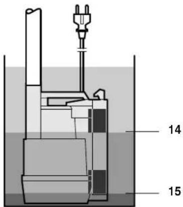

Caution!
The float switch must be able
to move in such way that the pump can not run dry.
6.2 Manual mode
Starting
- Push Mode selector (13) up to position M. The pump starts pumping.

Caution!
Do not let run pump unat-
tended in Manual mode. Risk of damage by pump running dry at low fluid levels.
Stopping
Contrary to Automatic operation the pump does not stop running when a certain water level is reached.
- Push Mode selector (13) down into position A. The pump stops when the float switch lowers to below the cut-out level.
7. Care and Maintenance

Danger!
Prior to all servicing:
- Switch Off.
- Unplug.
Service and repair work other than described here must be left to qualified specialists.
7.1 Periodic maintenance
For the pump to function perfectly at any time periodic maintenance is required. This also applies if the pump is used under heavy conditions, but does not run for extended periods of time (e.g. when used in well drains).
Yearly service
- Check pump casing, cables and float switch for damage.
- Rinse pump with clear water. Remove persistent soiling, e.g. algae desposits, with brush and dishwashing liquid.
- To flush the inside of the pump, place it into a container filled with clear water and switch ON briefly.
Rinsing the pump.
• Always rinse the pump with clear water when liquids were pumped that leave residues, such as chlorous water from a swimming pool.
Cleaning the float switch
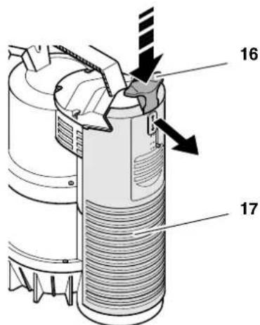
- Set Mode selector (16) to position "O", then press and hold the selector to unlock the float cover (17). Remove float cover.
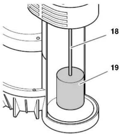
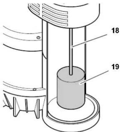
- Unhook float (18) complete with shaft (19) and clean.
- Clean walls and floor of float compartment.
- Reassemble pump.
Cleaning the intake port's cover

natural_image
Technical diagram of a mechanical assembly with numbered component (20), no readable text or symbols present- Loosen screws (20) and remove the cover.
- Clean impeller and all accessible inside surfaces of the casing. Remove any fibres which may have wound around the impeller shaft. Remove persistent soiling with brush and dishwashing liquid.
- Reassemble pump.
7.2 Pump storage

Caution!
Frost damages the pump and accessories, as both always contain water!
- When there is danger of freezing remove pump and accessories and store in frost-free location.
8. Trouble Shooting

Danger!
Prior to all servicing:
- Switch OFF.
- Unplug.
8.1 Fault finding
Pump does not run:
- No mains voltage.
- Check cables, plug, outlet and mains fuse.
- Mains voltage too low.
- Use only extension cables with sufficient lead cross section (see "Technical Specifications").
- Motor overheated, motor protection relay tripped.
- Remove cause for overheating (fluid pumped too hot? Pump blocked by foreign objects?)
- After cooling off the pump will switch ON again.
- Float switch does not switch the pump ON.
- Ensure a sufficient supply of water.
- Make sure the float switch can move unrestricted.
Motor hums but does not start:
- Pump blocked by foreign object.
- Clean pump.
Pump does not pump properly:
• Delivery head too high.
- Observe max. delivery head (see "Technical Specifications").
• Discharge hose kinked.
- Straighten discharge hose.
• Discharge hose leaky.
- Seal discharge hose, tighten screw fittings.
Pump runs very noisily:
- Pump primes air.
- Ensure a sufficient supply of water.
- Adjust float switch correctly.
- Hold pump at an angle when submerging.
Pump runs continuously:
- Float switch does not reach cut-out position.
- Make sure the float switch can move unrestricted.
- Set to Manual mode, unplug.
9. Repairs

Have your power tool serviced by a qualified repair person using only identical replacement parts. This will ensure that the safety of the power tool is maintained.
Contact your local Metabo representative if you have Metabo power tools requiring repairs. See www.metabo.com for addresses.
You can download a list of spare parts from www.metabo.com.
10. Environmental Protection
The packaging of the pump can be 100 % recycled.
Worn out power tools and accessories contain considerable amounts of valuable raw and plastic materials, which can be recycled.
These instructions are printed on paper produced with elemental chlorine free bleaching process.
11. Technical Specifications
| TP 7500Si TP 12000Si | |||
| Mains voltage | V | 230 ~ 1 | |
| Frequency Hz 50 | |||
| Rated output W 300 600 | |||
| Rated current | A | 1.4 | 2.5 |
| Fuse protection min. (time-lag or L-type circuit breaker) | A | 10 | 10 |
| Running capacitor | μF | 8 | 10 |
| Rated speed | min^-1 | 2800 | 2800 |
| Pump capacity max. | l/h | 7500 | 11700 |
| Delivery head max. | m | 6.5 | 9 |
| Delivery pressure max. | bar | 0.65 | 0.9 |
| Immersion depth max. | m | 7 | 7 |
| Standing water max. | mm | 3 | 3 |
| Max. temperature of primed medium | °C | 35 | 35 |
| Protection class | IP 68 | IP 68 | |
| Degree of protection | I | I | |
| Insulation class | B | B | |
| Materials | |||
| Pump casing | Polypropylene | Polypropylene | |
| Pump shaft | Stainless steel | Stainless steel | |
| Impeller | Noryl | Noryl | |
| Power cable (HO 5 RN-F) | m | 10 | 10 |
| Discharge port thread (AG = male) | 1 1/4" AG | 1 1/4" AG | |
| Dimensions (pump casing) | |||
| Height | mm | 285 | 320 |
| Width | mm | 185 | 190 |
| Diameter | mm | 227 | 230 |
| Weight | kg | 4.2 | 5.1 |
| Max. length of extension cable | |||
| at 3 x 1.0 mm^2 lead cross-section | m | 60 | 60 |
| at 3 x 1.5 mm^2 lead cross-section | m | 100 | 100 |
Position M = mode manuel
natural_image
Technical diagram of a mechanical assembly with screw fasteners and a circular component (no text or symbols)1 Bedienschuiver:
natural_image
Technical diagram of a mechanical assembly with screw fasteners and a circular component (no text or symbols)1 Betjeningselement:
Position M = manuel drift
6.1 Automatisk drift
natural_image
Technical diagram of a mechanical component with screw fasteners and a numbered label (20), no readable text or symbols beyond the number.natural_image
Technical illustration of a mechanical component with threaded parts and a circular base, labeled with number 20 (no text or symbols beyond label)- Upravljalni drsnik (16) potisnite v položaj "O" in ga držite pritisnje-nega, da sprostite zapah pokrova plavača (17). Snemite pokrov pla-vača.
natural_image
Technical diagram of a mechanical assembly with screw fasteners and a numbered component (no text or symbols)1 Käyttökytkin:
natural_image
Technical diagram of a mechanical assembly with screw fasteners and a circular component (no text or symbols)natural_image
Technical diagram of a mechanical component with screw fasteners and a numbered label (20), no readable text or symbols present.

- Table of Contents
- Please Read First!
- Range of Application and Pumping Media
- Safety
- Specified conditions of use
- General safety information
- Hazard by ambient con- ns!
- Danger: Hot water!
- Danger! Risk of electric shock!
- ⚠️ Danger by pump failures!
- Caution!
- Prior to Operation
- Discharge hose connection
- Note:
- Installation
- Operation
- Automatic mode
- Manual mode
- Starting
- Stopping
- Care and Maintenance
- Periodic maintenance
- Yearly service
- Rinsing the pump.
- Cleaning the float switch
- Cleaning the intake port's cover
- Pump storage
- Trouble Shooting
- Fault finding
- Pump does not run:
- Motor hums but does not start:
- Pump does not pump properly:
- Pump runs very noisily:
- Pump runs continuously:
- Repairs
- Environmental Protection
- Technical Specifications
- Automatisk drift
Brand : METABO
Model : TP 12000 SI
Category : Pump