BZ 3740 - Kitchen appliance CLATRONIC - Free user manual and instructions
Find the device manual for free BZ 3740 CLATRONIC in PDF.

| Product type | Beer dispenser |
| Brand | Clatronic |
| Model | BZ 3740 |
| Power supply | 220-240 V~, 50 Hz |
| Power consumption | 65 W |
| Protection class | II |
| Net weight | Approx. 6 kg |
| Refrigeration temperature range | 2 to 12 °C |
| Capacity | 5 L party kegs (standard and Heineken) |
| Propellant | CO₂ (16 g cartridges) |
| Refrigerant | C₅H₁₀ (cyclopentane) |
| Temperature adjustment | Yes, via ⊕/⊖ buttons |
| CO₂ pressure regulator | Yes, adjustable (+/→/-) |
| Compatible keg types | Rubber stopper, combination, vacuum, and Heineken kegs |
| Package contents | Dispenser, CO₂ cartridge, universal adapter, Heineken adapter, cleaning ball and hose |
| Maintenance and cleaning | Clean the dispensing unit, tap, and hose after each use; change water weekly |
| Safety | Ventilation required (15 cm around), overheating protection, pressurized CO₂ cartridge |
| Spare parts and repairability | Spare CO₂ cartridges, adapters, seals; repair by authorized technician |
Frequently Asked Questions - BZ 3740 CLATRONIC
User questions about BZ 3740 CLATRONIC
0 question about this device. Answer the ones you know or ask your own.
Ask a new question about this device
Download the instructions for your Kitchen appliance in PDF format for free! Find your manual BZ 3740 - CLATRONIC and take your electronic device back in hand. On this page are published all the documents necessary for the use of your device. BZ 3740 by CLATRONIC.
USER MANUAL BZ 3740 CLATRONIC
natural_image
Modern beer stand mixer with a glass of beer and black handle, no visible text or symbolsBedienungsanleitung
natural_image
Close-up of a metallic circular mechanical component with concentric rings and central hole (no text or symbols)Der Kombistopfen
natural_image
Close-up of a circular mechanical component with three circular holes, no visible text or symbolsnatural_image
Close-up of a circular, dark, metallic object with no visible text or symbolsnatural_image
Close-up of a hand pressing down on a metallic cylindrical container (no text or symbols visible)
ACHTUNG:
natural_image
Simple line drawing of a mechanical setup with a vertical rod and base, no text or symbols present.natural_image
Technical line drawing of a mechanical assembly showing internal components and cross-sectional view (no text or labels)natural_image
Technical line drawing of a mechanical assembly inside a circular frame (no text or symbols)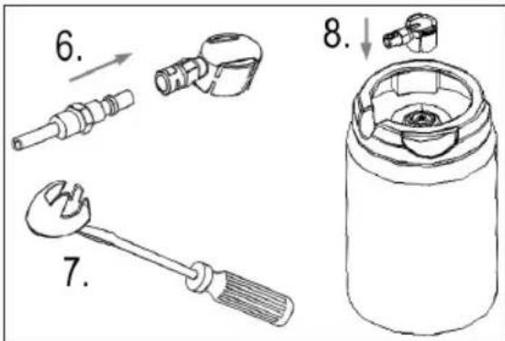
natural_image
Mechanical component diagram showing a cylindrical housing with internal components and directional arrows (no text or symbols)Bedienung

ACHTUNG:
natural_image
Technical line drawing of a mechanical assembly with no visible text or symbolsnatural_image
Technical line drawing of a mechanical device with lever and shaft (no text or symbols)natural_image
Technical line drawing of a mechanical assembly with no visible text or symbolsnatural_image
Close-up of a metallic circular mechanical component with concentric rings and central hole (no text or symbols visible)natural_image
Abstract circular pattern with three white circles at center, no text or symbols presentnatural_image
Close-up of a circular mechanical component with concentric rings and a central mark (no visible text or symbols)natural_image
Close-up of a hand pressing down on a metallic cylindrical object (no text or symbols visible)ATTENTION :
natural_image
Simple line drawing of a mechanical setup with a lever and base, no text or symbols presenti NOTE :
natural_image
Technical line drawing of a mechanical assembly showing internal components and a side view (no text or symbols)natural_image
Technical line drawing of a mechanical assembly inside a circular frame (no text or symbols)natural_image
Technical line drawing of a mechanical component with directional arrows indicating movement (no text or symbols)Utilisation

ATTENTION :
natural_image
Technical line drawing of a mechanical assembly with no visible text or symbolsnatural_image
Technical line drawing of a mechanical device with no visible text or symbolsnatural_image
Technical line drawing of a mechanical assembly with no visible text or symbolsClasse de climat:....SN, N
natural_image
Close-up of a circular mechanical component with concentric rings and central hole (no text or symbols visible)Tope de combinación
natural_image
Abstract circular design with three white circles inside a dark border (no text or symbols)natural_image
Close-up of a circular mechanical component with a central engraved symbol (no readable text or numbers)natural_image
Close-up of a hand pressing down on a metallic cylindrical object (no text or symbols visible)
ATENCIÓN:
natural_image
Simple line drawing of a mechanical setup with a lever and base, no text or symbols present
NOTA:
natural_image
Mechanical assembly diagram showing a rotating component with internal components and a directional arrow (no text or labels)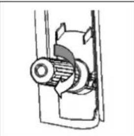
natural_image
Mechanical assembly diagram showing a gear and shaft assembly (no text or labels)natural_image
Technical line drawing of a mechanical assembly inside a circular frame (no text or symbols)natural_image
Technical line drawing of a mechanical component with directional arrows indicating movement (no text or symbols)Utilización

ATENCIÓN:
natural_image
Technical line drawing of a mechanical assembly with no visible text or symbolsnatural_image
Technical line drawing of a mechanical device with no visible text or symbolsnatural_image
Technical line drawing of a mechanical assembly with no visible text or symbolsThank you for choosing our product. We hope you will enjoy using the appliance.
Symbols in these Instruction Manual
Important information for your safety is specially marked. It is essential to comply with these instructions in order to avoid accidents and prevent damage to the appliance:

WARNING:
This warns you of dangers to your health and indicates possible injury risks.

CAUTION:
This refers to possible hazards to the appliance or other objects.

NOTE:
This highlights tips and information.
Contents
Overview of the Components....3
General Notes......41
Special Safety Instructions for this Appliance....42
Intended Use 43
Safety Information for CO₂ Cartridges .....43
Unpacking the Appliance....44
Overview of the Components/Scope of Delivery......44
Notes for Use....44
Installation 44
Preparation 45
Preparing the Beer Keg 45
Piercing the Beer Keg 45
Connecting the Beer Keg to the Appliance....46
Inserting the Carbon Dioxide (CO _2 ) Cartridge .....46
Heineken Kegs....46
Operation 47
Electric Connection 47
Turning the Appliance On/Off....47
Temperature Adjustment....47
Pressure Regulator for Carbon Dioxide....47
Drawing Beer 47
Replacing the Carbon Dioxide (CO _2 ) Cartridge.....47
Dismantling Beer Dispenser....48
Water Change....48
Cleaning 48
Housing 49
Drip Tray and Collecting Tray....49
Dispensing Unit, Beer Tap and Beer Hose....49
Storage....49
Troubleshooting....49
Technical Data....51
Disposal 51
Meaning of the "Dustbin" Symbol 51
General Notes
Read the operating instructions carefully before putting the appliance into operation and keep the instructions including the warranty, the receipt and, if possible, the box with the internal packing. If you give this appliance to other people, please also pass on the operating instructions.
- The appliance is designed exclusively for private use and for the envisaged purpose. This appliance is not fit for commercial use.
- Do not use it outdoors. Keep it away from sources of heat, direct sunlight, humidity (never dip it into any liquid) and sharp edges. Do not use the appliance with wet hands. If the appliance is humid or wet, unplug it immediately.
- When cleaning or putting it away, switch off the appliance and always pull out the plug from the socket (pull the plug itself, not the lead) if the appliance is not being used and remove the attached accessories.
- Do not operate the appliance without supervision. If you leave the room you should always turn the appliance off. Remove the plug from the socket.
- The appliance and the mains lead have to be checked regularly for signs of damage. If damage is found the appliance must not be used.
- Use only original spare parts.
- In order to ensure your children's safety, please keep all packaging (plastic bags, boxes, polystyrene etc.) out of their reach.

WARNING
Do not allow small children to play with the foil. There is a danger of suffocation!
Special Safety Instructions for this Appliance

WARNING:
Do not store any explosive substances such as aerosol containers containing flammable propellant inside the appliance.

CAUTION: Risk of overheating!
- Keep the ventilation slots free!
If the heat generated by the operation is not properly dissipated, it can result in overheating and fire. -
Position the appliance in such a way that a minimum space of 15 cm to other objects or walls around said appliance is provided.
-
Do not place the appliance on or directly next to heat sources such as ovens, radiators, etc.
- Do not expose the appliance to direct sunlight.
- Do not repair the appliance by yourself. Always contact an authorized technician. If the supply cord is damaged, it must be replaced by the manufacturer, its service agent or similarly qualified persons in order to avoid a hazard.
- This appliance can be used by children aged from 8 years and above and persons with reduced physical, sensory or mental capabilities or lack of experience and knowledge if they have been given supervision or instruction concerning use of the appliance in a safe way and understand the hazards involved.
• Children shall not play with the appliance. - Cleaning and user maintenance shall not be made by children without supervision.
- Observe the instructions in the chapter "Disposal".

CAUTION:
This appliance is not designed to be immersed in water during cleaning. Please follow the instructions that we have included for you in the chapter on “Cleaning”.
Intended Use
This dispenser serves for chilling dispensing beer from standard 5 litre party kegs.
It is intended for use in the household and in similar applications, such as:
- In personal kitchen areas in shops, offices and other work areas;
- By guests in hotels, motels and other accommodation;
• In bed and breakfast accommodation.
It is not intended for the following use:
- In agriculture;
- To use for camping;
• In catering and similar wholesale use.
This appliance may not be exposed to the rain.
Safety Information for CO _2 Cartridges
- The CO_2 cartridges are pressurised. Store the cartridges in a dry, cool place.
- The cartridges must not be subjected to temperatures above 50 °C. Protect from heat sources and direct sunlight.
- The CO_2 cartridges should have room temperature when used.
- Keep CO_2 cartridges out of the reach of children.
- Do not tamper with the cartridge.
-
Avoid contact with the cartridge at freezing temperatures (risk of frostbite) and do not use.
-
Only use the 16 g CO _2 cartridges intended for the dispenser. The use of other cartridges will invalidate the warranty.
- Do not remove the CO_2 cartridge before it is completely emptied.
- Only dispense of the CO_2 cartridge when empty.
Unpacking the Appliance
- Remove the appliance from its packaging.
- Remove all packaging material such as plastic films, filler material, cable ties and cardboard packaging.
- Sensitive surfaces are possibly protected with foil. Remove these foils.
- Check the content for any missing parts.
- In the event that the packaging content should be incomplete or if damages are noticeable, do not operate the appliance. Return it to the dealer immediately.
i NOTE:
There may be dust and production residue on the appliance. We recommend cleaning the appliance as described under “Cleaning”.
Overview of the Components / Scope of Delivery
1 Buttons ⊕ / (temperature adjustment)
2 LED temperature indicator
3 Pressure regulator for carbon dioxide
4 Beer hose cover
5 Fitting for the connections
6 CO, cartridge holder
7 Lid
8 CO, feed valve
9 Keg holder
10 Beer connection valve
11 Ventilation slots
12 Power cord
13 Main switch
14 Collecting tray
15 Drip tray
16 Drain lever
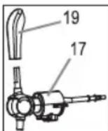
17 Beer tap
18 Lid opener
19 Tap handle
20 Cleaning balloon
21 Cleaning hose
22 Universal adapter
23 CO_2 cartridge
24 Adapter for Heineken kegs
No Illustration
Keg tap
Spare silicone ring for the keg tap thread
Spare CO _2 cartridge
44
Spare universal adapter
Spare adapter for Heineken kegs
Notes for Use
- When transporting the beer dispenser, always carry it holding the bottom edge and not by the beer tap, lid or power cord.
- Only use the dispenser with the correct beer keg.
- Do not place any objects on the dispenser.
- Follow the instructions on the kegs.
- Check that the kegs are tight and undamaged! Ensure that the keg lid is not dented so that the clamps of the dispensing unit can grip under the edge of the lid.
- Do not use beer that has already reached the best before date.
- Before placing the keg into the appliance, store it in a cool environment (but not in the freezer compartment) for 12 hours.
- Never shake the keg before using it.
- Do not expose the kegs to direct sunlight.
Installation
WARNING:
Before fitting or removing any parts, always disconnect the plug from the mains socket!
- Place the beer dispenser on a stable, horizontal, level and non-slip surface. Ensure that there is at least 15 cm of space around the dispenser for optimal operation.
- Place the drip tray on the collecting tray. Now, slide the collecting tray to the front of the appliance until it clicks into place. Make sure the collecting tray does not protrude beyond the base.
- Attach the tap handle. The flattened side of the handle points forward. Ensure that the silicone ring is in the right place. Make sure the handle is fully seated on the tap.
- Dispensing unit: Make sure the silicone ring has been inserted into the threaded part of the keg tap. Then put the fitting through the barrel holder. Make sure the lug on the fitting is seated in the recess of the keg holder. Screw the keg tap onto the fitting. Now the keg holder is sitting between the fitting and the keg tap.
Preparation
Preparing the Beer Keg
- Buy a standard 5 litre party keg of your choice.

CAUTION:
If the keg has been shaken (transport, etc.), the beer must be allowed to stand for a sufficient time prior to use.
- Cool the 5 litre party keg prior to use. The optimal drinking temperature is about 6 - 8 °C. The beer from a warmer keg is less refreshing. Heavy foaming can also result. To cool the keg in the beer dispenser, it is recommended to place it in the connected dispenser the day before. At a keg temperature of about 23 °C, it is recommended to wait 16 hours before pulling the first glasses of beer.

NOTE:
Use your domestic refrigerator to pre-cool the keg. This allows the cooling to process to be accelerated. Storing the 5 litre party keg in a refrigerator offers the advantage of always having a second keg ready to use.

CAUTION:
Never cool the party keg in a freezer as it can burst. Shock cooling can impair the quality of beer.
- The commercially available 5-liter party kegs are equipped with different stoppers. Depending on the stopper the party keg is provided with, it may be necessary to remove the keg stopper and insert one of the universal adapters. The various stoppers are described below.

CAUTION:
- Before removing the stopper, always first vent the keg as stated on the keg and allow to stand for a sufficient period so that the foam does not escape from the vent opening.
- Also observe the instructions on the respective keg regarding the handling of the different stoppers.
• Heineken kegs are described in a separate chapter.
You may use kegs with the following stoppers in this appliance:
The Rubber Stopper
Rubber stoppers do not require the use of any tools or adapters. Kegs with rubber stopper can simply be pierced with the keg tap as described in the chapter "Piercing the Beer Keg".
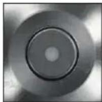
The Combination Stopper
The combination stopper is equipped with a red stopper lid. No tools or adapters are required. See the adjacent figure. When buying
natural_image
Close-up of a metallic circular disc with concentric rings and central hole (no text or symbols)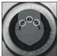
natural_image
Circular object with three white circles and a central dot, resembling a stylized face or emblem (no text or symbols)a keg with this cover, make sure it is provided with the sealing member that has been circled in the middle.
For the combination stopper, you first need to vent the keg and then remove the stopper lid with a powerful jerk. You may then pierce the keg as described in chapter "Piercing the Beer Keg".
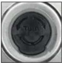
The Aerator Stopper
The aerator stopper is equipped with a black stopper lid. Kegs with this type of stopper must first be vented, as it is necessary with the combination stopper. After that, you may use a tool to remove this stopper, if necessary.
Once the stopper has been removed, the supplied universal adapter can be inserted into the bunghole in the keg and the following carried out.
natural_image
Close-up of a circular mechanical component with a central circular feature (no visible text or symbols)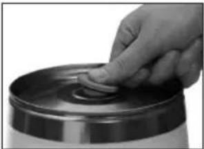
natural_image
Close-up of a hand inserting a coin into a metallic cylindrical container (no text or symbols visible)
CAUTION:
Do not dispose of the universal adapter after emptying the keg, but remove and clean with warm water and a small amount of mild washing up liquid and retain for reuse. Remove the adapter by gripping the edge of the rubber ring and pulling firmly towards you. Hold the keg firmly with the other hand to ensure that it does not tip over.
Piercing the Beer Keg
(Exception: Heineken kegs)
-
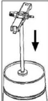
Take the dispensing unit and place it on the 5 litre beer keg, which should have been allowed to stand for minimum one hour so that no beer sprays out off the bunghole when the keg is tapped.
For this purpose, the tap located at the bottom of the dispensing unit must be moistened with water. -
Subsequently place it vertically on the tap opening of the stopper / universal adapter and push it downwards firmly and evenly into the keg. You may need to knock in the keg tap.
-
Attach the dispensing unit to the keg: First, hook one side of the keg holder at the edge of the keg. Then push the other side of the keg holder down until it clicks into place.
natural_image
Simple line drawing of a mechanical setup with a vertical rod and base, no text or symbols present.
NOTE:
After tapping the keg, the beer can be used for one week. A precondition is that the keg remains in the dispenser; the dispenser must remain on with a full CO_2 cartridge fitted.
Connecting the Beer Keg to the Appliance (Exception: Heineken kegs)
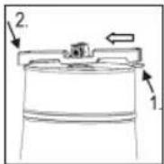
- Open the dispenser lid by pressing the lid open button.
- Use clean, cold water to fill the tank of the appliance up to the MAX mark.
- On the back of the beer tap you will see a button located below the beer hose. Press this button to release the cover (4). Lift the cover and bend the beer hose to the side.
- Place the keg with the mounted dispensing unit into the tank of the appliance.
- Put the beer hose back into the guide of the beer tap. Close the cover by first inserting the lug into the recess on the beer tap.
- Attach the beer hose to the beer connection valve of the dispensing unit (10). You may slightly turn the keg, if necessary. The click connection must audibly engage.

CAUTION:
- Check the beer connection valve and ensure it is properly attached to the dispensing unit before proceeding with the preparation.
- Turn the pressure regulator to the “—” position.
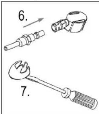
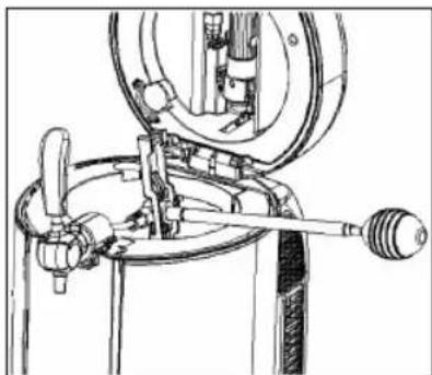
Inserting the Carbon Dioxide (CO _2 ) Cartridge (Exception: Heineken kegs)
- Remove the holder for the CO_2 cartridge (6) from the clamps of the lid. Turn and remove the holder.
- Insert an unopened 16 g CO _2 cartridge (with the round bottom first) into the holder.
3.

WARNING for frostbite:
When screwing it onto the thread, do not cover the ventilation opening of the holder with your bare hand. Use gloves to protect your hands. This will help to avoid cryogenic (cold) burns, if carbon dioxide accidentally escapes.

CAUTION: Pressure
- Check the position of the pressure regulator! It should be in the “—” position!
- Screw the holder with the CO _2 cartridge quickly and firmly onto the thread, so that no pressure escapes.
natural_image
Mechanical assembly diagram showing a clamping mechanism with no visible text or symbols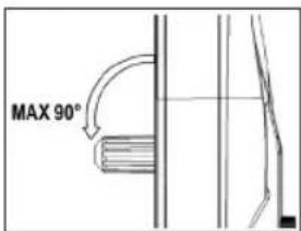
natural_image
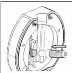
Mechanical assembly diagram showing a shaft and housing (no text or symbols)- Secure the holder with the CO_2 cartridge in the clamps of the lid.
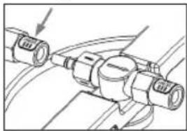
- Plug the CO_2 feed valve onto the connector on the fitting. The click connection must audibly engage.

CAUTION:
The carbon dioxide supply line is thus opened. The keg is pressurized.
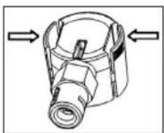
Heineken Kegs
The Heineken kegs already contain carbon dioxide (CO 2 ). You do not need the pressure regulator or the CO 2 cartridge. The pressure regulator on the lid remains without function.
- Use the button to open the lid of the appliance.
- Use cold water to fill the tank of the appliance up to the MAX mark.
- In the lid to the left of the holder for the CO2 cartridge you will see a clamp. Attach the hose of the CO2 feed valve to said clamp.
- Loosen the cover (4) as described above in order to bend the beer hose to the si
- Now, place the keg in the tank of the appliance.
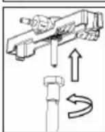
- Connect the beer hose to the included adapter for kegs of the Heineken brand. The click connection must audibly engage.
- Use a screwdriver to remove the green seal of the keg.
- Fit the adapter to the Heineken keg.
- Put the beer hose back into the guide of the tap. Close the cover by first inserting the lug into the recess on the beer tap.
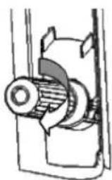
Disassembly:
If you want to remove the adapter from the Heineken keg, press the corrugated sides of the adapter while you remove it. Otherwise the adapter may be damaged.
natural_image
Mechanical component diagram showing a cylindrical housing with internal components and directional arrows (no text or symbols)Operation

CAUTION:
Before switching of the beer dispenser, always ensure that no 5 litre party keg is present in the dispenser as the beer in the keg becomes warm and is no longer fresh.
Close the lid of the appliance. It must audibly snap.
Electric Connection
- Ensure that your mains power corresponds with the specifications of the appliance. The specifications are printed on the type label.
- Connect the mains cable to a properly installed and earthed wall outlet.
Turning the Appliance On/Off
- Set the switch to the "I" position to turn the appliance on.
- The appliance is turned off when in the “O” position.
Temperature Adjustment

NOTE:
The appliance saves the most recently set cooling temperature while switching it off.
After switching the appliance on again, the display will show the current temperature of the inserted beer keg and the last set cooling temperature.
- You can choose a cooling temperature ranging from 2^ to 12^ .
- In order to display the set temperature, you may briefly press the ⏻ or ⏻ button.
- Press and hold the Ⓗ button to adjust the temperature setting.
Pressure Regulator for Carbon Dioxide (Exception: Heineken kegs)
Use the pressure regulator to select the appropriate pressure for your beer. As different beer varieties are carbonated to a differing extent, different pressures (saturation pressure) are required to ensure the quality of the respective beer. If a beer is dispensed with insufficient pressure, for example, it can make the beer taste flat, whilst too much pressure can make it too fizzy. If the beer should be too fizzy or flat, simply adjust the pressure accordingly. To be noted is that the CO_2 content in the beer initially changes over the course of time.

NOTE:
Make sure the pressure regulator is always in the “—” position when
• the beer drawing procedure is interrupted.
- you replace the CO_2 cartridge or the keg.
- In case you can no longer draw beer, even though there is still beer in the keg, or foaming requires too much time, slowly turn the pressure regulator towards “+” for
5 seconds. Then set the pressure regulator back to the “—” position.
Drawing Beer
1. Preparing glasses
Wash the glasses in hot water with a small amount of washing / up liquid. Rinse the glasses thoroughly each time before dispensing with cold, clear water. Ensure that all grease and residues are removed completely to avoid impairing foam formation.

NOTE:
The best results can be achieved by using glasses exclusively for beer to ensure that no residues from fat containing drinks (e. g. milk) are present.
2. Dispensing beer
Hold the glass under the beer tap at an angle. The tip of the outlet tube should not come into contact with the glass as this can impair the foam formation.

NOTE:
The foam produced when dispensing beer can be influenced by changing the angle of the glass.
Pull down the tap handle in one motion.

NOTE:
If the tap is only partly open, the beer may foam excessively as it is not able to flow out freely.
Allow the beer to run down the inside of the glass and slowly straighten the glass while dispensing until it is upright towards the end.
When the foam reaches the rim of the glass, close the beer tap by pushing back the beer tap handle.
Place the glass on the drip plate and wait until the foam has settled. Ensure that the glass is not located directly under the beer tap so that no drops fall into the bear foam.
Repeat the dispensing process until the beer and foam are in the correct proportion. This is the case when the head is about two finger's breadth high and slightly over the rim of the glass.
Replacing the Carbon Dioxide (CO₂) Cartridge (Exception: Heineken kegs)

WARNING for frostbite:
- Do not remove the CO_2 cartridge before it is completely emptied.
- A residual amount of CO_2 may still be present in the cartridge, which suddenly empties and results in the formation of ice.
Once no beer can be drawn, even though the pressure regulator is in the “+” position and there is still beer in the keg, replace the CO_2 cartridge.
- Switch off the appliance.
-
Disconnect the mains plug from the socket.
-
Turn the pressure regulator to the “—” position.
-
Use the button to open the lid of the appliance.
-
Remove the CO_2 feed valve from the connector on the fitting. To do this, press the white release button labeled "PRESS" that is located on the fitting.
natural_image
Pure mechanical diagram showing hoses and tubing without any text, numbers, or symbols- Insert a new 16 g CO 2 cartridge into the holder as described in the chapter "Inserting the Carbon Dioxide (CO 2 ) Cartridge".
Dismantling Beer Dispenser
To clean the beer dispenser and / or to replace the keg, it is necessary to remove the dispensing unit from the dispenser.

CAUTION:
Never remove the dispensing unit from the keg while it is still pressurized.
- Switch off the appliance.
- Disconnect the mains plug from the socket.
- Turn the pressure regulator to the “—” position.
- Use the button to open the lid of the appliance.
- Remove the CO _2 feed valve from the connector on the fitting. To do this, press the white release button labelled "PRESS" that is located on the fitting.
- Place a container underneath the beer tap.
- Keep the tap handle pressed until the appliance is no longer pressurized. There must be no more beer or foam escaping.
- Remove the beer hose from the beer connection valve of the dispensing unit. To do this, press the white release button labelled "PRESS" that is located on the fitting.
- Now you are able to remove the keg with the dispensing unit from the tank of the appliance.

NOTE:
This may require some effort due to the keg being secured by a suction cup located at the bottom of the appliance.
- Detach the dispensing unit from the keg:
See the adjacent figure. First, remove the right holder. Then push the left holder out of the keg's edge.
- Remove the dispensing unit from the keg by evenly pulling it out.

NOTE:
As the beer tap may not be moist during extraction, removal may take some effort.
- The dispensing unit can now be cleaned as described in the chapter "Cleaning" and subsequently installed on a new keg as described in the chapter "Piercing the Beer Keg".

NOTE:
If necessary, replace the CO_2 cartridge as described in the chapter “Replacing the Carbon Dioxide ( CO_2 ) Cartridge”.
Water Change
There is no need to change the water in the tank every time a beer keg has been emptied. Exchange the water weekly.
- Remove the collecting tray from the appliance.
- After disconnecting the appliance from the power supply, place it near a table edge and make sure the front feet are still on the table.
- Place an empty container than can hold about 1 litre of water under the edge of the table.
- To open the outlet, pull the drain lever down. The tank gets emptied.
- Use a clean cloth to wipe the tank.
- Release the drain lever.
- Use clean water to fill the tank up to the MAX mark.
- Repeat the procedure in order to rinse the tank.
Cleaning

WARNING:
- Before cleaning, always remove the mains plug and wait until the appliance has cooled down.
- Do not immerse the appliance in water. Otherwise this might result in an electric shock or fire.

CAUTION:
- Do not use a wire brush or any abrasive items.
- Do not use any acidic or abrasive detergents.
• The dispensing unit is not dishwasher-safe.
Clean the appliance prior to initial commissioning and after each use.
In order to keep the quality of the dispensed beer at a consistently high level, it is important to clean the dispenser thoroughly.
Housing
- Empty the tank completely. (Refer to chapter "Water Change").
- Use a clean cloth to wipe the tank.
- Clean the lid and the exterior of the housing with a damp cloth. You may add some manual washing-up liquid to the cloth.
- Use a cloth for final drying.
Drip Tray and Collecting Tray
- Remove both the drip tray and the collecting tray from the appliance.
- Pour the accumulated beer into a sink.
- Clean both components with hot water. If required, you can add some manual washing-up liquid to the rinsing bath.
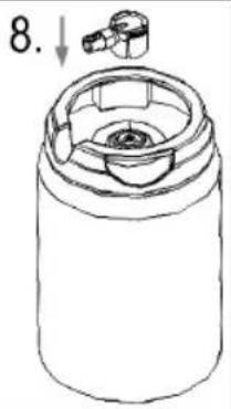
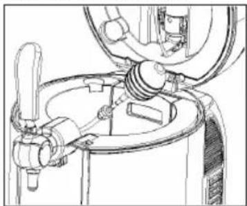
Dispensing Unit, Beer Tap and Beer Hose
For this procedure you will need the cleaning balloon, the cleaning hose, a container that holds about 2 litres of clean, warm water and an empty container the water will be drained into.
natural_image
Technical line drawing of a mechanical device with no visible text or symbols- Place the empty container underneath the beer tap.
- Fill the cleaning balloon with the warm water.
- Connect the dispensing unit to the beer hose. The click connection must audibly engage.
- Plug the cleaning balloon onto the end of the keg tap.
- Use one hand to open the tap. Use your other hand to hold and press the cleaning balloon. Pump all the water from the balloon through the dispensing unit and the beer tap.
- Repeat this procedure several times.
- Remove the dispensing unit from the beer hose.
- Disassemble the dispensing unit into its 3 components. To do this, turn the keg tap and remove it from the fitting.
- Clean these components under running warm water. Thoroughly rinse the keg tap.
In order to clean the beer tap with the beer hose but without the dispensing unit, proceed as follows:
natural_image
Technical line drawing of a mechanical assembly with no visible text or symbols- Connect the cleaning hose with the balloon.
- Attach the cleaning hose to the tip of the beer hose.
- Use one hand to open the beer tap. Use your other hand to hold and press the cleaning balloon. Pump all the water from the balloon through the beer hose.
- Repeat this procedure until the beer hose is clean.
Storage
- Clean the appliance as described and let it dry completely.
• We recommend that you store the appliance in its original packaging when it is not to be used for a longer period.
• Always store the appliance at a well ventilated and dry place outside the reach of children.
Troubleshooting
If a problem occurs, it is often just a small matter. Before contacting our customer service, please note the following:
| Problem Possible cause Solution | ||
| The appliance does not work. | The appliance is not connected to mains power. Check the wall outlet with a different appliance. | |
| The appliance is defective. Contact our service or a repair centre. | ||
| Problem Possible cause | Use Solution | |
| No beer is dispensed. | The 5 litre party keg is empty or there is not a 5 litre party keg in the beer dispenser. | Place a new 5 litre party keg in the dispenser. |
| The CO2 cartridge is empty. Change the CO | 2 cartridge. | |
| The keg tap is not fitted.The keg is not correctly tapped. | Attach the dispensing unit to the keg by using the keg tap. Tap the keg correctly. | |
| The tap handle is not correctly installed. Install the tap handle correctly. | ||
| Too much foam is produced when dispensing. | The 5 litre party keg is not cold enough. Cool the 5 litre party keg longer. | |
| The 5 litre party keg was shaken. Allow the 5 litre part keg to stand in the beer dispenser for a while. | ||
| The beer does not flow freely out of the tube. Open the beer tap fully. | ||
| The glass is held upright when dispensing. Tilt the glass when dispensing so that the beer is able to run down the side of the glass. | ||
| The CO2 pressure in the keg is too high. | Turn the pressure regulator to the “—” position. It takes some time until the pressure in the keg is relieved and the amount of foam is reduced. | |
| Not enough foam is produced while dispensing. | The CO2 pressure in the keg is too low. | Slowly turn the pressure regulator towards “+” for 5 seconds. |
| The beer is too cold. | Allow the keg to stand in the dispenser for while. The temperature is then corrected by the appliance. | |
| There are grease, washing-up liquid or residues in the glass. | Wash the glass thoroughly and subsequently rinse with cold water. | |
| The glass is too warm. | Rinse the glass with cold water. | |
| The glass is dry. Rinse the glass with cold water. | ||
| The beer turns cloudy. | The beer is too cold. | Allow the keg to stand in the dispenser for while. The temperature is then corrected by the appliance. |
| The beer hose is not clean. | Clean the beer hose. | |
| The beer was incorrectly shock- chilled prior to using the beer dispenser. | Use a correctly chilled keg. | |
| The beer is too warm. | The keg was not chilled long enough. | Chill the keg longer. |
| The vents are covered. Insufficient space next to and behind the dispenser. | Uncover the vents.Position the dispenser so that there is minimum 15 cm space on all sides. | |
| The beer tastes flat. | The CO2 pressure is too low. | Slowly turn the pressure regulator towards “+” for 5 seconds. |
| The best before date has expired. | Use a new keg. | |
| The keg has been tapped too long. | Use a new keg. | |
| The beer runs too slowly out of the beer tap. | The CO2 cartridge is empty. Change the CO | 2 cartridge. |
| The CO2 pressure in the keg is too low. | Slowly turn the pressure regulator towards “+” for 5 seconds. | |
| The beer does not flow freely out of the tube. Open the beer tap fully. | ||
| The dispenser does not close. | The dispensing unit is not correctly installed and protrudes from the dispenser. | Install the dispensing unit correctly. |
| It is difficult to install the dispensing unit on the keg. | The keg tap was not moistened prior to tapping. | Wet the keg tap with cold water. |
Technical Data
Model: BZ 3740
Power supply: 220-240 V\~, 50 Hz
Power consumption: 65 W
Protection class:....II
Net weight: .... approx. 6 kg
Cooling power: 2-12°C
Climate class: SN, N
Capacity: .... Commercially available 5-liter party keg .... Heineken kegs (with included CO _2 )
Propellant: C5H10
The right to make technical and design modifications in the course of continuous product development remains reserved.
This appliance has been tested according to all relevant current CE guidelines, such as electromagnetic compatibility and low voltage directives, and has been constructed in accordance with the latest safety regulations.
Disposal
Meaning of the "Dustbin" Symbol
Protect our environment: do not dispose of electrical equipment in the domestic waste.
Please return any electrical equipment that you will no longer use to the collection points provided for their disposal.
This helps avoid the potential effects of incorrect disposal on the environment and human health.
This will contribute to the recycling and other forms of re-utilisation of electrical and electronic equipment.
Information concerning where the equipment can be disposed of can be obtained from your local authority.
Instrukcja obsługi
natural_image
Close-up of a metallic circular disc with concentric rings and central hole (no text or symbols)natural_image
Close-up of a circular object with three white circles on its surface, resembling a stylized heart or abstract design (no text or symbols visible)natural_image
Close-up of a circular mechanical component with a curved, glossy surface (no visible text or symbols)natural_image
Close-up of a hand inserting a coin into a metallic cylindrical container (no text or symbols visible)
UWAGA:
natural_image
Simple line drawing of a mechanical setup with a lever and base, no text or symbols presentnatural_image
Mechanical assembly diagram showing a rotating component with internal components and a directional arrow (no text or labels)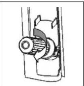
natural_image
Mechanical assembly diagram showing a gear and housing component (no text or labels)natural_image
Technical line drawing of a mechanical assembly inside a circular frame (no text or symbols)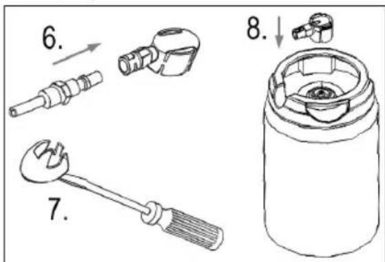
natural_image
Technical line drawing of a mechanical component with directional arrows indicating movement (no text or symbols)Obstuga

UWAGA:
natural_image
Pure mechanical diagram showing hoses and tubing without any text, numbers, or symbolsnatural_image
Technical line drawing of a mechanical device with lever and housing (no text or symbols)natural_image
Technical line drawing of a mechanical assembly with no visible text or symbolsCTC Clatronic Sp. z o.o
Ul. Brzeska 1
45-960 Opole
Usuwanie
natural_image
Close-up of a circular mechanical component with concentric rings and central hole (no text or symbols visible)Kombinációs dugasz
natural_image
Circular object with three white circles inside, resembling a stylized heart or lens (no text or symbols)natural_image
Close-up of a circular mechanical component with concentric rings and a central curved feature (no visible text or symbols)natural_image
Close-up of a hand inserting a coin into a metallic container (no text or symbols visible)
VIGYÁZAT:
natural_image
Simple line drawing of a mechanical setup with a vertical rod and base, no text or symbols present.i MEGJEGYZÉS:
natural_image
Technical line drawing of a mechanical assembly with two views: top shows internal components, bottom shows external gears (no text or labels)natural_image
Mechanical component diagram showing a cylindrical housing with internal components and directional arrows (no text or symbols)Kezelés