GF23mmF4 R LM WR - Camera FUJIFILM - Free user manual and instructions
Find the device manual for free GF23mmF4 R LM WR FUJIFILM in PDF.
User questions about GF23mmF4 R LM WR FUJIFILM
0 question about this device. Answer the ones you know or ask your own.
Ask a new question about this device
Download the instructions for your Camera in PDF format for free! Find your manual GF23mmF4 R LM WR - FUJIFILM and take your electronic device back in hand. On this page are published all the documents necessary for the use of your device. GF23mmF4 R LM WR by FUJIFILM.
USER MANUAL GF23mmF4 R LM WR FUJIFILM
text_image
Technical diagram of a camera lens with numbered parts for identification and assembly reference.text_image
Technical diagram showing mechanical assembly with numbered components and directional arrows indicating motion or movement.レンズフードの取り付け方
text_image
Diagram illustrating camera lens adjustment process with numbered steps and component viewsレンズフードの取り外し方
text_image
Diagram of a camera lens with labeled parts and directional arrow indicating rotation or movement日本語
絞りリング
Be sure to read these notes before use
Safety Notes
Thank you for your purchase of this product. For repair, inspection, and internal testing, contact your FUJIFILM dealer.
• Make sure that you use the lens correctly. Read these safety notes and the camera Owner's Manual carefully before use.
• After reading these safety notes, store them in a safe place.
About the Icons
The icons shown below are used in this document to indicate the severity of the injury or damage that can result if the formation indicated by the icon is ignored and the product is used incorrectly as a result.
| This icon indicates that death or serious injury can result if the information is ignored. | |
| This icon indicates that personal injury or material damage can result if the information is ignored. |
The icons shown below are used to indicate the nature of the instructions which are to be observed.
| Triangular icons tell you that this information requires attention ("Important"). | |
| Circular icons with a diagonal bar tell you that the action indicated is prohibited ("Prohibited"). | |
| Filled circles with an exclamation mark indicate an action t be performed ("Required"). |
| WARNING | |
| Do not use in the bathroom or shower | Do not immerse in or expose to water.Failure to observe this precaution can cause a fi re or electric shock. |
| Do not disassemble | Do not disassemble (do not open the case).Failure to observe this precaution can cause fi re, electric shock, or injury due to product malfunction. |
| Do not touch internal parts must | Should the case break open as the result of a fall or other accident, do not touch the exposed parts.Failure to observe this precaution could result in electric shock or in injury from touching the damaged parts. Remove the camera battery immediately, taking care to avoid injury or electric shock, and take the product to the point of purchase for consultation. |
| Do not place on unstable surfaces. The product may fall, causing injury. | |
| Do not view the sun through the lens or camera view fi ndFailure to observe this precaution can cause permanent visual impairment. | |
| CAUTION | |
| Do not use or store in locations that are exposed to steam, or smoke or are very humid or extremely dusty. Failure to observe this precaution can cause fi re or electric shock. | |
| Do not leave in direct sunlight or in locations subject to very high temperatures, such as in a closed vehicle on a sunny day.Failure to observe this precaution can cause fi re. | |
 | |
| Keep out of the reach of small children. This product could cause injury in the hands of a child. | |
| Do not handle with wet hands.Failure to observe this precaution can cause electric shock. | |
| Keep the sun out of the frame when shooting backlit subjects.Sunlight focused into the camera when the sun is in or close to the frame can cause fire or burns. | |
| When the product is not in use, replace the lens caps and store out of direct sunlight. Sunlight focused by the lens can cause fire or burns. | |
| Do not carry the camera or lens while they are attached to a tripod. The product can fall or strike other objects, causing injury. |
For Customers in the U.S.A.
Tested To Comply With FCC Standards FOR HOME OR OFFICE USE
FCC Statement: This device complies with Part 15 of the FCC Rules. Operation is subject to the following two conditions: (1) This device may not cause harmful interference, and (2) this device must accept any interference received, including interference that may cause undesired operation.
CAUTION: This equipment has been tested and found to comply with the limits for a Class B digital device, pursuant to Part 15 of the FCC Rules. These limits are designed to provide reasonable protection against harmful interference in a residential installation. This equipment generates, uses, and can radiate radio frequency energy and, if not installed and used in accordance with the instructions, may cause harmful interference to radio communications. However, there is no guarantee that interference will not occur in a particular installation. If this equipment does cause harmful interference to radio or television reception, which can be determined by turning the equipment off and on, the user is encouraged to try to correct the interference by one or more of the following measures:
- Reorient or relocate the receiving antenna.
- Increase the separation between the equipment and receiver.

EN-2
ENGLISH
- Connect the equipment into an outlet on a circuit different from that to which the receiver is connected.
- Consult the dealer or an experienced radio/TV technician for help.
- You are cautioned that any changes or modifications not expressly approved in this manual could void the user's authority to operate the equipment.
Notes on the Grant: To comply with Part 15 of the FCC Rules, this product must be used with a Fujifi Im-specific ed ferrite-core A/V cable, USB cable, and DC supply cord.
For Customers in Canada
CAN ICES-3 (B)/NMB-3(B)
CAUTION: This Class B digital apparatus complies with Canadian ICES-003.
IMPORTANT SAFETY INSTRUCTIONS
- Read these instructions.
- Keep these instructions.
- Heed all warnings.
- Follow all instructions.
- Do not use this apparatus near water (excluding waterproof products).
- Clean only with a dry cloth.
- Do not block any ventilation openings. Install in accordance with the manufacturer's instructions.
- Do not install near any heat sources such as ra-
diators, heat registers, stoves, or other apparatus (including amplifiers) that produce heat.
- Protect the power cord from being walked on or pinched particularly at plugs, convenience receptacles, and the point where they exit from the apparatus.
- Only use attachments/accessories specified by the manufacturer.
- Unplug this apparatus during lightning storms or when unused for long periods of time.
- Refer all servicing to qualified service personal. Servicing is required when the apparatus has been damaged in any way, such as power supply cord or plug is damaged, liquid has been spilled or objects have fallen into the apparatus, the apparatus has been exposed to rain or moisture, does not operate normally, or has been dropped.
Disposal of Electrical and Electronic Equipment in Private Households
In the European Union, Norway, Iceland and Liechtenstein: This symbol on the product, or in the manual and in the warranty, and/or on its packaging indicates that this product shall not be treated as household waste. Instead it should be taken to an applicable collection point for the recycling of electrical and electronic equipment.
By ensuring this product is disposed of correctly, you will help prevent potential negative consequences to the environment and human health, which could otherwise be caused by inappropriate waste handling of this product.
The recycling of materials will help to conserve natural resources. For more detailed information about recycling this product, please contact your local city office, your household waste disposal service or the shop where you purchased the product.
In Countries Outside the European Union, Norway, Iceland and Liechtenstein: If you wish to discard this product, including the batteries or accumulators, please contact your local authorities and ask for the correct way of disposal.
Australian RCM

EN-3
ENGLISH
Before Using This Product
Some lens features are not available with older versions of the camera fi rmware. Be sure to update the camera fi rmware to the latest version. Instructions on viewing the camera fi rmware version and updating camera fi rmware are available from the following website:
http://www.fujifilm.com/support/digital_cameras/software/#firmware
If you do not have access to a computer, support is available from the local distributor listed in the "FUJIFILM Worldwide Network" material provided with your camera.
Product Care
- When using a lens hood, do not pick up or hold the camera using only the hood.
-
Keep the lens signal contacts clean.
-
Use a blower to remove dust and lint from the glass surfaces of the lens or fi lter. To remove smudges and fi ingerprints, apply a small amount of lens cleaner to a soft, clean cotton cloth or lens-cleaning tissue and clean from the center outwards using a circular motion, taking care not to leave smears or touch the glass with your fi ngers.
- Never use organic solvents such as paint thinner or benzene to clean the lens.
- Attach the front and rear caps when the lens is not in use.
- Store the lens and filter in cool, dry locations to prevent mold and rust. Do not store in direct sunlight or with naphtha or camphol moth balls.
- Keep the lens dry. Rusting can cause irreparable damage. Wipe off rain and water droplets.
• Leaving the lens in extremely hot locations could cause damage or warping.
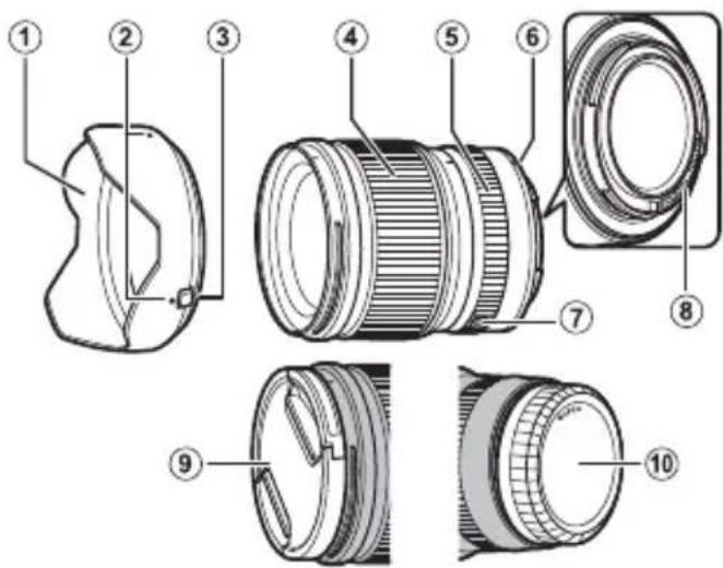
Parts of the Lens
GF23mmF4 R LM WR
text_image
Exploded view diagram of a camera lens with numbered parts for identification① Lens hood
② Mounting marks
③ Hood latch release
④ Focus ring
⑤ Aperture ring lock release
⑥ Mounting marks (focal length)
⑦ Aperture ring
⑧ Lens signal contacts
⑨ Front lens cap
⑩ Rear lens cap
① The lens mount includes a rubber ring to ensure that the lens remains dust- and splash-proof. The ring can be replaced for a fee at any FUJIFILM service center.
Supplied Accessories
- Front lens cap
-
Rear lens cap
-
Lens hood
- Lens pouch
EN-5
ENGLISH
Attaching the Lens
See the camera manual for information on attaching and removing lenses.
① This lens is for use exclusively with FUJIFILM G mounts and can not be used with X mounts.
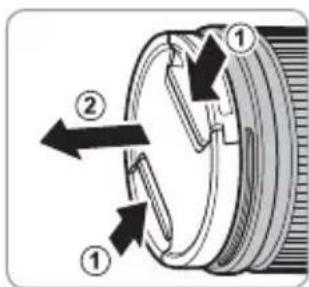
Removing the Caps
Remove the caps as shown.
text_image
Diagram of a mechanical device with numbered components and directional arrows indicating motion or flow.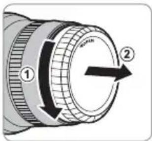
text_image
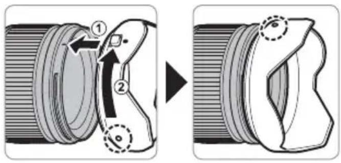
Diagram of a camera lens with labeled parts and directional arrows indicating rotation or movement.Attaching the Hood
When attached, lens hoods reduce glare and protect the front lens element.
text_image
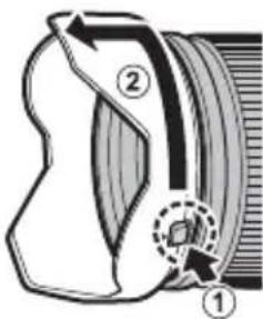
Diagram illustrating camera lens adjustment process with numbered steps and component viewsRemoving the Hood
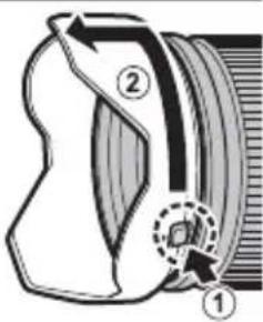
To remove the hood, press and hold the hood latch release while rotating the hood counterclockwise.
text_image
Diagram of a camera lens system with labeled parts and directional arrows indicating componentsEN-7 ENGLISH
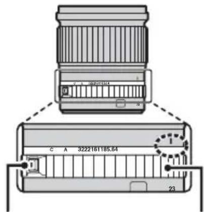
The Aperture Ring
Rotate the lens aperture ring to choose the aperture (f-number).
① C (c): Set aperture to the value chosen with the camera command dial.
② A (3): Set aperture to the value chosen automatically by the camera.
③ Other values (5.64): Set aperture to the selected value.
To select C or A, or to select another value after selecting C or A, press the aperture ring lock release while rotating the aperture ring.
text_image
C A 3222161185.64 23Aperture ring lock release
Aperture ring
Specifications
| Type GF23mmF4 R LM WR | |
| Lens construction | 15 elements in 12 groups (including 2 aspherical, 3 extra-low-dispersion, and 1 super extra-low-dispersion elements) |
| Focal length (35 mm format equivalent) | f=23 mm (18 mm) |
| Angle of view 99.9° | |
| Max. aperture f/4 | |
| Min. aperture f/32 | |
| Aperture controlNumber of bladesStop size | 9 (rounded diaphragm opening)IVI EV (19 stops) |
| Focus range (measured from focal plane) | 38 cm-infinity |
| Max. magnification 0.09 × | |
| External dimensions: Diameter × Length* (approx.)* distance from camera lens mount fl ange | ∅89.8 × 103.0 mm |
| Weight* (approx.)* excluding caps and hoods | 845 g |
| Filter size | ∅82 mm |
① Improvements may result in unannounced changes to specifications and appearance.
① Owing to how this lens is constructed, the “Distance indicator” displayed by the camera may in some cases differ from the a focus distance. Use the “Distance indicator” as a guide only.
This lens uses linear motors to ensure fast and accurate auto focus while maintaining the highest image quality. When the can is turned off, the lens is disconnected from the camera body, or the playback feature is turned on, there may be an audible so and slight physical vibration due to the linear motor's magnets being disengaged. This is perfectly normal and will not negate affect image quality or lens performance.
EN-9 ENGLISH
Pour votre sécurité
http://www.fujifilm.com/support/digital_cameras/software/#firmware
text_image
Exploded view diagram of a camera lens with numbered parts for identificationtext_image
Diagram of a mechanical device with numbered components and directional arrows indicating motion or force directions.
text_image
Diagram of a mechanical component with numbered parts and directional arrow indicating rotation or movementtext_image
Diagram illustrating camera lens adjustment process with numbered steps and rotation arrowstext_image
Diagram of a camera lens with labeled parts and an arrow indicating direction, likely illustrating optical or mechanical components.http://www.fujifilm.com/support/digital_cameras/software/#firmware
text_image
Exploded view diagram of a camera lens with numbered parts for identificationtext_image
Diagram of a mechanical component with numbered parts and directional arrows indicating motion or flow.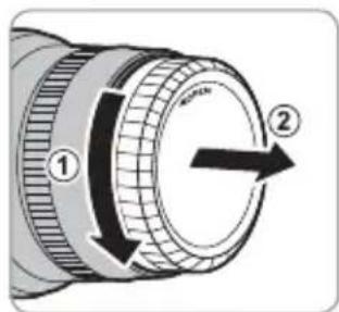
text_image
Diagram of a mechanical component with numbered parts and directional arrows indicating motion or flow.text_image
Diagram illustrating camera lens adjustment process with numbered steps and directional arrowsAbnehmen der Haube
text_image
Diagram of a mechanical device with labeled parts and directional arrows indicating motion or forceDE-7 DEUTSCH
Der Blendenring
http://www.fujifilm.com/support/digital_cameras/software/#firmware
text_image
Exploded view diagram of a camera lens with numbered parts for identificationtext_image
Diagram of a mechanical device with numbered components and directional arrows indicating motion or flow.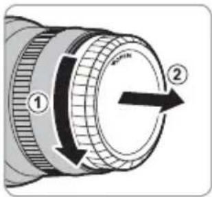
text_image
Diagram of a mechanical component with numbered parts and directional arrow indicating rotation or movementES-6 ESPAÑOL
text_image
Diagram illustrating camera lens adjustment process with numbered steps and component viewstext_image
erta pre- ① ②http://www.fujifilm.com/support/digital_cameras/software/#firmware
text_image
Exploded view diagram of a camera lens with numbered parts for identification① Zonnekap
② Bevestigingsmarkeringen
③ Kap-ontgrendelingsschuifj e
④ Scherpstelring
⑤ Ontgrendeling diafragmaring
⑥ Bevestigingsmarkeringen (brandpuntsafstand)
⑦ Diafragmaring
⑧ Lenssignaalcontacten
⑨ Voorste lensdop
⑩ Achterste lensdop
text_image
Diagram of a mechanical device with numbered components and directional arrows indicating motion or flow.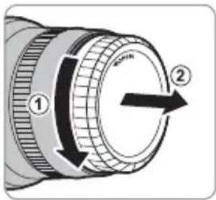
text_image
Diagram of a mechanical component with numbered parts and directional arrow indicating rotation or movementDe zonnekap bevestigen
text_image
Diagram illustrating camera lens adjustment process with numbered steps and rotation arrowstext_image
Diagram of a camera lens with labeled parts and directional arrows indicating motion or movementNL-7 NEDERLANDS
De diafragmaring
http://www.fujifilm.com/support/digital_cameras/software/#firmware
text_image
Technical diagram of a camera lens with numbered parts for identification and assembly reference.① Motljusskydd
②Monteringsmarkeringar
③Motljusskyddets frigöringsknapp
④ Fokusring
⑤ Frigöra bländarringen
⑥Monteringsmarkeringar (brännvidd)
⑦Bländarring
⑧ Objektivsignalkontakter
⑨ Främre objektivlock
⑩ Bakre objektivlock
text_image
Diagram of a mechanical device with numbered parts and directional arrows indicating motion or flow
text_image
Diagram of a mechanical component with numbered parts and directional arrow indicating rotation or movementSV-6 SVENSKA
text_image
Diagram illustrating camera lens adjustment process with numbered steps and component viewstext_image
Diagram of a camera lens system with labeled parts and directional arrows indicating light pathBländarringen
http://www.fujifilm.com/support/digital_cameras/software/#firmware
text_image
Technical diagram of a camera lens with numbered parts for identification and assembly reference.① Solblender
② Monteringsmerker
③ Solblenderutlöser
④ Fokusring
⑤ Utløs lås for blenderåpningsring
⑥ Monteringsmerker (brennvidde)
⑦ Blenderring
⑧ Objektivets signalkontakter
⑨ Fremre objektivdeksel
⑩ Bakre objektivdeksel
text_image
Diagram of a mechanical device with numbered components and directional arrows indicating motion or flow.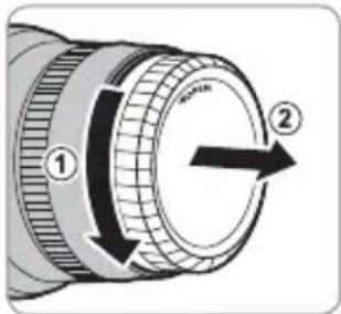
text_image
Diagram of a mechanical component with numbered parts and directional arrow indicating rotation or movementtext_image
Diagram illustrating camera lens adjustment process with numbered steps and magnified detail viewFjerne solblenderen
text_image
Diagram of a mechanical device with labeled parts and directional arrows indicating motion or forceBlenderringen
http://www.fujifilm.com/support/digital_cameras/software/#firmware
text_image
Technical diagram of a camera lens with numbered parts for identificationtext_image
Diagram of a mechanical device with numbered components and directional arrows indicating motion or flow.
text_image
Diagram of a mechanical component with numbered parts and directional arrow indicating rotation or movementtext_image
Diagram illustrating camera lens adjustment process with numbered steps and component viewstext_image
Diagram illustrating a mechanical or optical device with labeled parts ① and ②, showing directional arrows and a circular inset detail.Himmenninrengas
text_image
Technical diagram of a camera lens with numbered parts for identificationtext_image
Technical diagram showing mechanical assembly with numbered components and directional arrows indicating motion or flow.Установка бленды
text_image
Diagram illustrating camera lens adjustment process with numbered steps and directional arrowsСнятие бленды
text_image
Diagram illustrating a mechanical or optical device with labeled parts ① and ②, showing directional arrows and a highlighted section.Кольцо диафрагмы
http://www.fujifilm.com/support/digital_cameras/software/#firmware
text_image
Exploded view diagram of a camera lens with numbered parts for identificationtext_image
Diagram of a mechanical device with numbered components and directional arrows indicating motion or flow.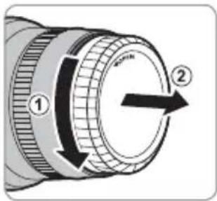
text_image
Diagram of a mechanical component with numbered parts and directional arrow indicating rotation or movementIT-6 ITALIANO
Montaggio paraluce
text_image
Diagram illustrating camera lens adjustment process with numbered steps and rotation arrowstext_image
Diagram of a mechanical device with labeled parts and directional arrows indicating motion or forceLa ghiera diaframma
http://www.fujifilm.com/support/digital_cameras/software/#firmware
text_image
Exploded view diagram of a camera lens with numbered parts for identificationtext_image
Technical diagram showing two mechanical components with numbered parts and directional arrows indicating motion or movement.text_image
Diagram illustrating camera lens adjustment process with numbered steps and component viewshttp://www.fujifilm.com/support/digital_cameras/software/#firmware
text_image
Exploded view diagram of a camera lens with numbered parts for identificationtext_image
Diagram of a mechanical device with numbered components and directional arrows indicating motion or flow.
text_image
Diagram of a mechanical component with numbered parts and directional arrow indicating rotation or movementtext_image
Diagram illustrating camera lens adjustment process with numbered steps and directional arrowsZdejmowanie osłony
text_image
Diagram of a camera lens with labeled parts and directional arrows indicating motion or movementPierścień przysłony
http://www.fujifilm.com/support/digital_cameras/software/#firmware
text_image
Exploded view diagram of a camera lens with numbered parts for identificationtext_image
Technical diagram showing mechanical assembly with numbered components and directional arrows indicating motion or movement.中文简
ZHS-6
安装遮光罩
text_image
Diagram illustrating camera lens adjustment process with numbered steps and angle annotations取下遮光罩
text_image
Diagram of a camera lens system with labeled parts and directional arrows indicating components光圈环
旋转镜头光圈环可选择光圈(f值)。
http://www.fujifilm.com/support/digital_cameras/software/#firmware
text_image
Exploded view diagram of a camera lens with numbered parts for identificationtext_image
Technical diagram showing two mechanical components with numbered parts and directional arrows indicating motion or assembly.安裝遮光罩
text_image
Diagram illustrating camera lens adjustment process with numbered steps and component views取下遮光罩
若要取下遮光罩,請按住遮光罩釋放栓扣並同時逆時針旋轉遮光罩。
text_image
Diagram of a camera lens system with labeled parts and directional arrows indicating components光圈環
旋轉鏡頭光圈環可選擇光圈(f值)。
http://www.fujifilm.com/support/digital_cameras/software/#firmware
text_image
Technical diagram of a camera lens with numbered parts for identification and assembly reference.text_image
Diagram of a mechanical device with numbered components and directional arrows indicating motion or flow.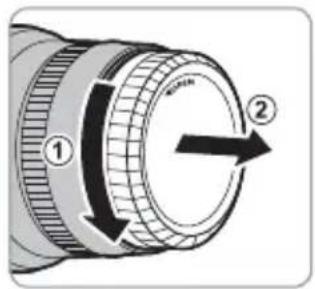
text_image
Diagram of a mechanical component with numbered parts and directional arrows indicating motion or rotation.후드부착
text_image
Diagram illustrating camera lens adjustment process with numbered steps and component views후드제거
text_image
Diagram of a camera lens system with labeled parts and directional arrows indicating components한글
KO-7
조리개 링
text_image
Diagram of a camera lens with labeled parts and directional arrows indicating motion or positioningtext_image
Diagram illustrating camera lens adjustment process with numbered parts and directional arrowsزالالة蓝图اء
تركيب الاددسة
text_image
Diagram of a mechanical device with numbered parts and directional arrows indicating motion or flow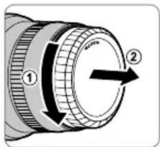
text_image
Diagram of a mechanical component with numbered parts and directional arrows indicating motion or flow.text_image
Diagram of a mechanical component with numbered parts labeled ①, ②, and ③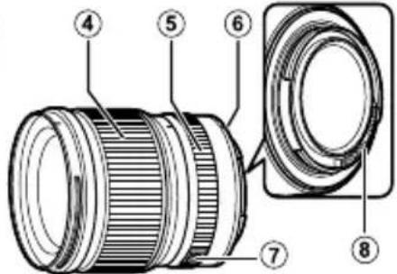
text_image
Technical diagram of a camera lens with numbered parts for identification
natural_image
Close-up of a mechanical component with threaded end and labeled part (9), no readable text or symbols beyond the number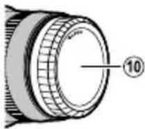
الإكسوارات المرفقة
• واقية العدسة
.الأمامي
• حقبة العدسة
• الخلفي
AR-5
عربي