IPE84571IB - Cooker AEG - Free user manual and instructions
Find the device manual for free IPE84571IB AEG in PDF.
User questions about IPE84571IB AEG
0 question about this device. Answer the ones you know or ask your own.
Ask a new question about this device
Download the instructions for your Cooker in PDF format for free! Find your manual IPE84571IB - AEG and take your electronic device back in hand. On this page are published all the documents necessary for the use of your device. IPE84571IB by AEG.
USER MANUAL IPE84571IB AEG
natural_image
Simple geometric diagram of four circles arranged in a 2x2 grid within a square frame (no text or symbols)IPE84571IB
text_image
QR code image with a document icon in the center, likely linking to a digital resource or webpage.PER UNS RESULTATS PERFECTES
How to install your AEG induction hob flush installation

4. DESCRIPCIÓ DEL PRODUCTE
chemical
Chemical structure diagram showing a vertical double-headed arrow and a branched alkene with double-headed bond5.12 Hob ^2 Hood
natural_image
Diagram showing a checklist with three circular items and a checkmark (no text or symbols)
100-160mm
natural_image
Simple diagram showing two circular objects with a checkmark and dashed lines, no text or symbols present.
160 mm
text_image
Diagram showing a grid with dashed boxes and a speech bubble containing rectangular blocks, likely representing a UI or interface layout.text_image
Diagram showing three groups of circular objects with checkmarks, likely illustrating a counting or classification exercise.text_image
Warning sign with crossed-out black 'X' and exclamation mark, indicating no clear safety or hazard6.3 FlexiBridge Mode Big Bridge
text_image
Diagram showing a grid layout with dashed boxes and a speech bubble containing rectangular blocks, including a star symbol.natural_image
Top-down diagram of a room layout with two furniture units and a checkmark (no text or symbols)text_image
Safety warning sign with crossed-out circle, triangle, and exclamation mark
text_image
Warning sign with cross symbol and warning triangle, indicating no clear safety or hazard6.4 FlexiBridge Mode Max Bridge
text_image
Diagram showing a grid with dashed boxes and a speech bubble containing rectangular blocks, alongside a star symbol.natural_image
Simple line drawing of a rectangular room with a central circular element and a checkmark on the wall (no text or symbols)text_image
Warning sign with crossed-out circle and exclamation mark, indicating no liability or failure6.5 PowerSlide
flowchart
graph TD
    A["Downward Arrow"] --> B["Arrow to Right"]
    B --> C["Circle Icon: Teacher with Sun, Chef, and Box"]
    C --> D["Arrow to Downward Arrow"]

natural_image
Simple diagram of a circular object with two side handles, enclosed in a dashed rectangular frame (no text or symbols)LJ
9
natural_image
Simple diagram with a central circular element and two small protrusions, enclosed in dashed rectangular boxes (no text or symbols)- 6
natural_image
Simple line drawing of a CD/DVD icon inside a rectangle with dashed border (no text or symbols)r
3
text_image
Diagram illustrating a smart home control system with a cooking pot, signal detection, and wireless signal output.
text_image
How to install your AEG induction hob flush installation4. PRODUKTBESKRIVELSE
text_image
Safety warning illustration showing a cooking pot with warning symbol and three safety symbols below.chemical
Chemical structure diagram showing a vertical double-headed arrow and two separate branched alkene-like structures with double-headed arrows indicating resonance or equilibrium.5.12 Hob²Hood
natural_image
Simple diagram of a checklist with a checkmark and a circular object, no text or symbols present.
100-160mm
natural_image
Simple line drawing of a room with two circular objects and a checkmark, no text or symbols present
160 mm
text_image
Diagram showing a grid with dashed boxes and a speech bubble containing rectangular blocks, likely representing a UI or interface layout.text_image
Three-panel diagram showing a grid of circular objects with checkmarks, likely illustrating a selection or counting exercise.text_image
Warning sign with crossed-out circle and exclamation mark, indicating no clear safety or hazard6.3 FlexiBridge Big Bridge-funktion
text_image
Diagram showing a grid layout with dashed boxes and a speech bubble containing rectangular blocks, likely representing a UI or system interface.natural_image
Top-down diagram of a room layout with an oval object and a circular component, no text or symbols present.text_image
Safety warning sign with crossed-out circle and warning triangle, indicating no intersection or absence of hazard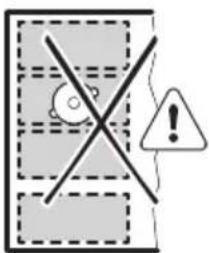
text_image
Warning sign with cross symbol and warning triangle, indicating no clear safety or hazardtext_image
Diagram showing a grid with dashed lines and a speech bubble containing rectangular blocks, alongside a star symbol.natural_image
Simple line drawing of a rectangular room with a central circular element and a checkmark on the wall (no text or symbols)text_image
Warning sign with cross symbol, warning triangle, and exclamation mark6.5 PowerSlide
flowchart
graph TD
    A["Vertical Arrow"] --> B["Horizontal Arrow"]
    C["Circle Icon"] --> D["Star Icon"]
    E["Arrow"] --> F["Arrow to Center"]
i
natural_image
Simple diagram with a circular object inside a square frame, no text or symbols presentLJ
9

natural_image
Simple diagram with a central circular element and two small protrusions, enclosed in dashed rectangular boxes (no text or symbols)- 6
natural_image
Simple line drawing of a circular object with two small protrusions, enclosed in a dashed rectangle (no text or symbols)r
3
7.2 Lyden under drift
Hvis du kan høre:
7.3 Öko Timer (Eco-timer)
text_image
Diagram illustrating a smart heating or monitoring system with a pot, antenna, and wireless signal detection.
| How to install your AEG induction hob flush installation |
4. BESCHRIJVING VAN HET PRODUCT
4.3 OptiHeat Control (3-staps restwarmte-indicator)

WAARSCHUWING!
5.11 Stroommanagement
chemical
Chemical structure diagram showing a vertical double-headed arrow and a branched alkene with double-headed arrows indicating resonance or bond formation.5.12 Hob²Hood
natural_image
Diagram showing a checklist with three circular items and a checkmark (no text or symbols)
100-160mm
natural_image
Simple diagram showing two circular objects with a checkmark and dashed lines, no text or symbols present.
160 mm
6.2 FlexiBridge Standaardmodus
text_image
Diagram showing a grid layout with dashed boxes and a speech bubble containing rectangular blocks, likely representing a digital interface or layout.text_image
Diagram showing three panels of a grid with circular objects and checkmarks, likely illustrating a selection or counting process.Onjuiste positie kookgerei:
text_image
Warning sign with crossed-out circle and exclamation mark, indicating no clear safety or hazard6.3 FlexiBridge Big Bridge-modus (grote overbrugging)
text_image
Diagram showing a grid with dashed lines and a speech bubble containing rectangular blocks, alongside a star symbol and a speech bubble with a star.natural_image
Top-down diagram of a room layout with two circular fixtures and a checkmark pointing to a central oval (no text or symbols)Onjuiste positie kookgerei:
text_image
Safety warning sign with crossed-out circle, triangle, and exclamation mark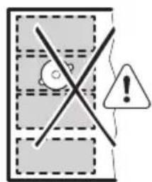
text_image
Warning sign with cross symbol and warning triangle, indicating no clear safety or hazard6.4 FlexiBridge Max Bridge mode (Maximale overbrugging)
text_image
Diagram showing a grid layout with dashed boxes and a speech bubble containing rectangular blocks, alongside a speech bubble icon.natural_image
Simple line drawing of a rectangular room with a central circular element and a checkmark on the wall (no text or symbols)Onjuiste positie kookgerei:

text_image
Warning sign with cross symbol, warning triangle, and exclamation mark6.5 PowerSlide
natural_image
Simple diagram with a central circular element and dashed rectangular outlines, no text or symbols present.LJ
9
natural_image
Simple diagram with a central circle and two small protrusions, enclosed in dashed rectangular boxes (no text or symbols)- 6
natural_image
Simple diagram with a circular object and three small protrusions, enclosed in a dashed rectangle (no text or symbols)r
3
7.3 Öko Timer (Eco-timer)
natural_image
Simple line drawing of a roof-mounted structure with a sloped roof and a pot, connected to a wall-mounted platform with wireless signal icon (no text or symbols)8. ONDERHOUD EN REINIGING

WAARSCHUWING!
9. PROBLEEMOPLOSSING

WAARSCHUWING!
Thank you for choosing this AEG product. We have created it to give you impeccable performance for many years, with innovative technologies that help make life simpler – features you might not find on ordinary appliances. Please spend a few minutes reading to get the very best from it.
Visit our website to:

Get usage advice, brochures, trouble shooter, service and repair information: www.aeg.com/support

Register your product for better service: www.registeraeg.com

Buy Accessories, Consumables and Original spare parts for your appliance: www.aeg.com/shop
CUSTOMER CARE AND SERVICE
Always use original spare parts.
When contacting our Authorised Service Centre, ensure that you have the following data available: Model, PNC, Serial Number.
The information can be found on the rating plate.

Warning / Caution-Safety information

General information and tips

Environmental information
Subject to change without notice.
CONTENTS
- SAFETY INFORMATION....70
- SAFETY INSTRUCTIONS.... 73
- INSTALLATION....75
- PRODUCT DESCRIPTION....76
- DAILY USE....77
- FLEXIBLE INDUCTION COOKING AREA....81
- HINTS AND TIPS......85
- CARE AND CLEANING.... 87
- TROUBLESHOOTING....87
- TECHNICAL DATA....89
- ENERGY EFFICIENCY....90
- ENVIRONMENTAL CONCERNS....90
1. ⚠ SAFETY INFORMATION
Before the installation and use of the appliance, carefully read the supplied instructions. The manufacturer is not responsible for any injuries or damage that are the result of incorrect
installation or usage. Always keep the instructions in a safe and accessible location for future reference.
1.1 Children and vulnerable people safety
- This appliance can be used by children aged from 8 years and above and persons with reduced physical, sensory or mental capabilities or lack of experience and knowledge if they have been given supervision or instruction concerning the use of the appliance in a safe way and understand the hazards involved. Children of less than 8 years of age and persons with very extensive and complex disabilities shall be kept away from the appliance unless continuously supervised.
- Children should be supervised to ensure that they do not play with the appliance.
- Keep all packaging away from children and dispose of it appropriately.
- WARNING: The appliance and its accessible parts become hot during use. Keep children and pets away from the appliance when in use and when cooling down.
- If the appliance has a child safety device, it should be activated.
- Children shall not carry out cleaning and user maintenance of the appliance without supervision.
1.2 General Safety
- This appliance is for cooking purposes only.
- This appliance is designed for single household domestic use in an indoor environment.
- This appliance may be used in, offices, hotel guest rooms, bed & breakfast guest rooms, farm guest houses and other similar accommodation where such use does not exceed (average) domestic usage levels.
-
WARNING: The appliance and its accessible parts become hot during use. Care should be taken to avoid touching heating elements.
-
WARNING: Unattended cooking on a hob with fat or oil can be dangerous and may result in fire.
- Smoke is an indication of overheating. Never use water to extinguish the cooking fire. Switch off the appliance and cover flames with e.g. a fire blanket or lid.
- WARNING: The appliance must not be supplied through an external switching device, such as a timer, or connected to a circuit that is regularly switched on and off by a utility.
- CAUTION: The cooking process has to be supervised. A short term cooking process has to be supervised continuously.
- WARNING: Danger of fire: Do not store items on the cooking surfaces.
- Metallic objects such as knives, forks, spoons and lids should not be placed on the hob surface since they can get hot.
- Do not use the appliance before installing it in the built-in structure.
- Do not use a steam cleaner to clean the appliance.
- After use, switch off the hob element by its control and do not rely on the pan detector.
- If the glass ceramic surface / glass surface is cracked, switch off the appliance and unplug it from the mains. In case the appliance is connected to the mains directly using junction box, remove the fuse to disconnect the appliance from power supply. In either case contact the Authorised Service Centre.
- If the supply cord is damaged, it must be replaced by the manufacturer, an authorized Service or similarly qualified persons in order to avoid a hazard.
- WARNING: Use only hob guards designed by the manufacturer of the cooking appliance or indicated by the manufacturer of the appliance in the instructions for use as suitable or hob guards incorporated in the appliance. The use of inappropriate guards can cause accidents.
2. SAFETY INSTRUCTIONS
2.1 Installation

WARNING!
Only a qualified person must install this appliance.

WARNING!
Risk of injury or damage to the appliance.
- Remove all the packaging.
- Do not install or use a damaged appliance.
- Follow the installation instructions supplied with the appliance.
- Keep the minimum distance from other appliances and units.
• Always take care when moving the appliance as it is heavy. Always use safety gloves and enclosed footwear. - Seal the cut surfaces of the cabinet with a sealant to prevent moisture from causing swelling.
- Protect the bottom of the appliance from steam and moisture.
- Do not install the appliance next to a door or under a window. This prevents hot cookware from falling from the appliance when the door or the window is opened.
• Each appliance has cooling fans on the bottom. - If the appliance is installed above a drawer:
- Do not store any small pieces or sheets of paper that could be pulled in, as they can damage the cooling fans or impair the cooling system.
- Keep a distance of minimum 2 cm between the bottom of the appliance and parts stored in the drawer.
- Remove any separator panels installed in the cabinet below the appliance.
2.2 Electrical Connection

WARNING!
Risk of fire and electric shock.
- All electrical connections should be made by a qualified electrician.
• The appliance must be earthed.
- Before carrying out any operation make sure that the appliance is disconnected from the power supply.
- Make sure that the parameters on the rating plate are compatible with the electrical ratings of the mains power supply.
- Make sure the appliance is installed correctly. Loose and incorrect electricity mains cable or plug (if applicable) can make the terminal become too hot.
- Use the correct electricity mains cable.
- Do not let the electricity mains cable tangle.
- Make sure that a shock protection is installed.
- Use the strain relief clamp on the cable.
- Make sure the mains cable or plug (if applicable) does not touch the hot appliance or hot cookware, when you connect the appliance to a socket.
- Do not use multi-plug adapters and extension cables.
- Make sure not to cause damage to the mains plug (if applicable) or to the mains cable. Contact our Authorised Service Centre or an electrician to change a damaged mains cable.
- The shock protection of live and insulated parts must be fastened in such a way that it cannot be removed without tools.
- Connect the mains plug to the mains socket only at the end of the installation. Make sure that there is access to the mains plug after the installation.
- If the mains socket is loose, do not connect the mains plug.
- Do not pull the mains cable to disconnect the appliance. Always pull the mains plug.
- Use only correct isolation devices: line protecting cut-outs, fuses (screw type fuses removed from the holder), earth leakage trips and contactors.
- The electrical installation must have an isolation device which lets you disconnect the appliance from the mains at all poles. The isolation device must have a contact opening width of minimum 3 mm.
2.3 Use

WARNING!
Risk of injury, burns and electric shock.
- Do not change the specification of this appliance.
- Remove all the packaging, labelling and protective film (if applicable) before first use.
- Make sure that the ventilation openings are not blocked.
- Do not let the appliance stay unattended during operation.
- Set the cooking zone to "off" after each use.
- Do not put cutlery or saucepan lids on the cooking zones. They can become hot.
- Do not operate the appliance with wet hands or when it has contact with water.
- Do not use the appliance as a work surface or as a storage surface.
- If the surface of the appliance is cracked, disconnect immediately the appliance from the power supply. This to prevent an electrical shock.
- Users with a pacemaker must keep a distance of minimum 30 cm from the induction cooking zones when the appliance is in operation.
- When you place food into hot oil, it may splash.
- Do not use aluminum foil or other materials between the cooking surface and the cookware, unless otherwise specified by the manufacturer of this appliance.
- Use only accessories recommended for this appliance by the manufacturer.

WARNING!
Risk of fire and explosion.
- Fats and oil when heated can release flammable vapours. Keep flames or heated objects away from fats and oils when you cook with them.
- The vapours that very hot oil releases can cause spontaneous combustion.
• Used oil, that can contain food remnants, can cause fire at a lower temperature than oil used for the first time.
- Do not put flammable products or items that are wet with flammable products in, near or on the appliance.

WARNING!
Risk of damage to the appliance.
- Do not keep hot cookware on the control panel.
- Do not put a hot pan cover on the glass surface of the hob.
- Do not let cookware boil dry.
- Be careful not to let objects or cookware fall on the appliance. The surface can be damaged.
- Do not activate the cooking zones with empty cookware or without cookware.
- Cookware made of cast iron or with a damaged bottom can cause scratches on the glass / glass ceramic. Always lift these objects up when you have to move them on the cooking surface.
2.4 Care and cleaning
- Clean the appliance regularly to prevent the deterioration of the surface material.
- Switch off the appliance and let it cool down before cleaning.
- Do not use water spray and steam to clean the appliance.
- Clean the appliance with a moist soft cloth. Use only neutral detergents. Do not use abrasive products, abrasive cleaning pads, solvents or metal objects, unless otherwise specified.
2.5 Service
• To repair the appliance contact the Authorised Service Centre. Use original spare parts only.
- Concerning the lamp(s) inside this product and spare part lamps sold separately: These lamps are intended to withstand extreme physical conditions in household appliances, such as temperature, vibration, humidity, or are intended to signal information about the operational status of the appliance. They are not intended to be used in other applications and are not suitable for household room illumination.
2.6 Disposal

WARNING!
Risk of injury or suffocation.
- Contact your local authority for information on how to dispose of the appliance.
- Disconnect the appliance from the mains supply.
- Cut off the mains electrical cable close to the appliance and dispose of it.
3. INSTALLATION

WARNING!
Refer to Safety chapters.
3.1 Before the installation
Before you install the hob, write down the information below from the rating plate. The rating plate is on the bottom of the hob.
Serial number ....
3.2 Built-in hobs
Only use the built-in hobs after you assemble the hob into correct built-in units and work surfaces that align to the standards.
3.3 Connection cable
- The hob is supplied with a connection cable.
• To replace the damaged mains cable, use the cable type: H05V2V2-F which withstands a temperature of 90 °C or higher. Contact an Authorised Service Centre. The connection cable may only be replaced by a qualified electrician.
3.4 Assembly
If you install the hob under a hood, please see the installation instructions of the hood for the minimum distance between the appliances.
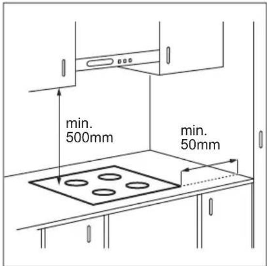
If the appliance is installed above a drawer, the hob ventilation can warm up the items stored in the drawer during the cooking process.
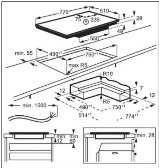
text_image
770 510 75 335 28 550 49 min. 55 490*1 750*1 max R5 R10 12 7 12 min. 1500 490*1 750*1 514*1 774*1 min. min. 12 60 min. 28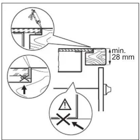
text_image
min. 28 mmFind the video tutorial "How to install your AEG induction hob flush installation" by typing out the full name indicated in the graphic below.

YouTube
www.youtube.com/electrolux www.youtube.com/aeg
How to install your AEG induction hob flush installation
4. PRODUCT DESCRIPTION
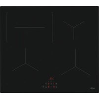
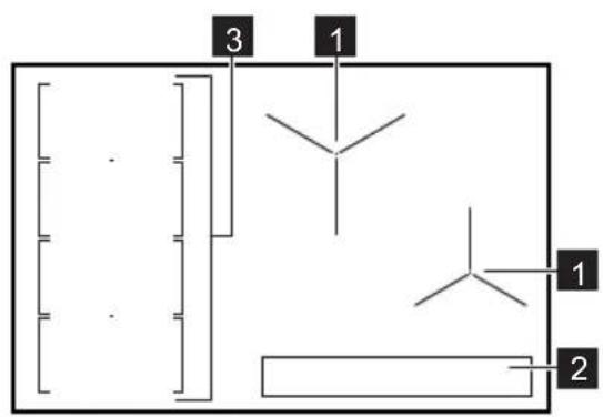
4.1 Cooking surface layout

text_image
3 1 1 21 Induction cooking zone
2 Control panel
3 Flexible induction cooking area consisting of four sections
4.2 Control panel layout
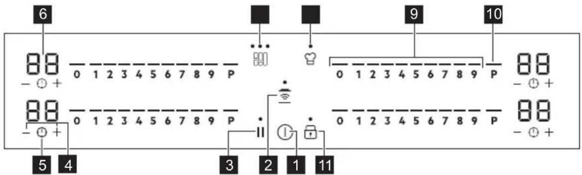
text_image
6 8 8 - + 0 1 2 3 4 5 6 7 8 9 P 8 8 - + 0 1 2 3 4 5 6 7 8 9 P 5 4 3 2 1 11 9 8 8 - + 0 1 2 3 4 5 6 7 8 9 P 8 8 - +To see the control panel and the zone positions activate the appliance with ①
Use the sensor fields to operate the appliance. The displays, indicators and sounds tell which functions operate.
| Sensor field | Function Comment | |
| 1 | ➊ | ON / OFF To activate and deactivate the hob. |
| 2 | nurses | Hob ^2 Hood To activate and deactivate the manual mode of the function. |
| 3 | || | Pause To activate and deactivate the function. |
| 4 | +/- | - To increase or decrease the time. |
| 5 | ➌ | - To set the timer function. |
| 6 | - Timer display To show the time in minutes. | |
| 7 | 880 | FlexiBridge (Flexible Bridge) To switch between three modes of the function. |
| 8 | nurses | PowerSlide To activate and deactivate the function. |
| 9 | - Control bar To set a heat setting. | |
| 10 | P | PowerBoost To activate the function. |
| 11 | Lock / Child Safety Device To lock / unlock the control panel. | |
4.3 OptiHeat Control (3 step Residual heat indicator)

WARNING!
/ F As long as the indicator is on, there is a risk of burns from residual heat.
The induction cooking zones produce the heat necessary for the cooking process directly in the bottom of the cookware. The glass ceramic is heated by the heat of the cookware.
The indicators / appear when a cooking zone is hot. They show the level of
the residual heat for the cooking zones you are currently using.
The indicator may also appear:
• for the neighbouring cooking zones even if you are not using them,
- when hot cookware is placed on cold cooking zone,
- when the hob is deactivated but the cooking zone is still hot.
The indicator disappears when the cooking zone has cooled down.
5. DAILY USE

WARNING!
Refer to Safety chapters.
5.1 Activating and deactivating
Touch ① for 1 second to activate or deactivate the hob.
The control panel comes on after you activate the hob and goes off after you deactivate the hob.
When the hob is deactivated you can only see ①
5.2 Automatic Switch Off
The function deactivates the hob automatically if:
- you do not place any cookware on the hob for 50 seconds,
- you do not set the heat setting for 50 seconds after you place the cookware,
- you spill something or put something on the control panel for more than 10 seconds (a pan, a cloth). When you hear the acoustic signal, the hob deactivates. Remove the object or clean the control panel.
• the hob gets too hot (e.g. when a saucepan boils dry). Let the cooking zone cool down before you use the hob again. - you do not deactivate a cooking zone or change the heat setting. After some time, the hob deactivates.
The relation between the heat setting and the time after which the hob deactivates:
Heat setting The hob deactivates after
1 - 2 6 hours
3 - 4 5 hours
5 4 hours
6 - 9 1.5 hours
5.3 Using the cooking zones

CAUTION!
Do not place hot cookware on the control panel. There is a risk of damage to the electronic parts.

text_image
Safety warning illustration showing a cooking pot with warning symbol and three safety symbols below.Place the cookware in the centre of the selected zone. Induction cooking zones adapt to the dimension of the bottom of the cookware automatically.
Once the pot is detected, the heat setting 0 comes on.
5.4 Heat setting
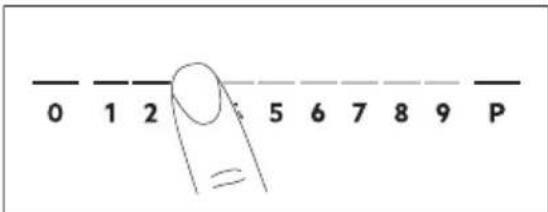
text_image
0 1 2 5 6 7 8 9 P- Press the desired heat setting on the control bar. You can also move your finger along the control bar to set or change the heat setting for a cooking zone.
- To deactivate a cooking zone, press 0. Once you place a pot on the cooking zone and set the heat setting, it remains the same for 50 seconds after you remove the pot. The control bar blinks for the second half of that time. If you place the pot on the cooking zone again within this time, the heat setting reactivates. Otherwise the cooking zone deactivates.
5.5 PowerBoost
This function activates more power for the appropriate induction cooking zone, depending on the cookware size. The function can be activated only for a limited period of time.
Touch P to activate the function for the cooking zone.
The function deactivates automatically.
i
For maximum duration values, refer to "Technical data".
5.6 Timer
Count Down Timer
Use this function to specify how long a cooking zone should operate during a single cooking session.
First set the heat setting, then set the function.
- Touch to activate the function or change the time.
The timer digits and the indicators and come on the display.
If the timer is not set, + and disappear after 3 seconds.
- Touch or to set the time (00 - 99 minutes).
After 3 seconds, the timer starts to count down automatically. The indicators + and — disappear.
When the time comes to an end, a signal sounds and flashes. To stop the signal, touch ⏻
To deactivate the function: touch ⚠The indicators + and → come on. Use or + to set □□ on the display. Alternatively, set the heat level to 0. As a result, a signal sounds and the timer is cancelled.
Minute Minder
You can use this function when the hob is activated but no cooking zone operates.
Place a pot on a cooking zone to see ⏻ symbol.
-
Touch to activate the function.
-
Touch or to set the time.
The function starts automatically after 4 seconds.
When you set the function, you can remove the pot.
When the time comes to an end, a signal sounds and flashes. Touch to stop the signal.
To deactivate the function: touch ⏻. The indicators and light up. Use or to set on the display.
i
The function has no effect on the operation of any cooking zone.
5.7 Pause
This function sets all cooking zones that operate to the lowest heat setting.
When the function is active, ⏻ or ⏱ symbols can be used.
Press || to activate the function.
The heat setting is lowered to 1.
To deactivate the function: press ||The previous heat setting comes on.
5.8 Lock
You can lock the control panel while the hob operates. It prevents an accidental change of the heat setting.
Set the heat setting first.
Touch to activate the function.
To deactivate the function, touch 🔒
i
When you deactivate the hob, you also deactivate this function.
5.9 Child Safety Device
This function prevents an accidental operation of the hob.
Activate the hob first and do not set the heat setting.
Touch 📁 until signal sounds and the indicator comes on to activate the function. The control bars disappear. Deactivate the hob.

When you deactivate the hob, the function is still active.
To deactivate the function for only one cooking time: Activate the hob with ⏻ ≡ comes on. Touch ≡ until signal sounds and the indicator comes off. The control bar appears. Set the heat setting within 50 seconds. You can operate the hob. When you deactivate the hob with Ⓤ the function is still active.
To deactivate the function permanently: Activate the hob and do not set the heat setting. Touch ⏻ until signal sounds and the indicator comes off. The control bars appear. Deactivate the hob.
5.10 OffSound Control (Deactivating and activating the sounds)
Deactivate the hob first.
- Touch for 3 seconds to activate the function.
The display comes on and goes out.
- Touch for 3 seconds.
b0 or bcomes on.
- Touch of the timer to choose one of the following:
- the sounds are off
- the sounds are on
- Wait until the hob deactivates automatically to confirm your selection.
When the function is set to by you can hear the sounds only when:
- you touch
- Minute Minder comes down
- Count Down Timer comes down
- you put something on the control panel.
5.11 Power management
If multiple zones are active and the consumed power exceeds the limitation of the power supply, this function divides the available power between all cooking zones. The hob controls heat settings to protect the fuses of the house installation.
- Cooking zones are grouped according to the location and number of the phases in the hob. Each phase has a maximum electricity loading of 3680 W. If the hob reaches the limit of maximum available power within one phase, the power of the cooking zones will be automatically reduced.
- For cooking zones that have a reduced power, the control panel shows the maximum possible heat settings.
- If a higher heat setting is not available reduce it for the other cooking zones first.
- The activation of the function depends on the number and size of pots.
Refer to the illustration for possible combinations in which power can be distributed among the cooking zones.
chemical
Chemical structure diagram showing a vertical double-headed arrow and two branched alkene-like structures with double-headed arrows indicating resonance or equilibrium.5.12 Hob²Hood
It is an advanced automatic function which connects the hob to a special hood. Both the hob and the hood have an infrared signal communicator. Speed of the fan is defined automatically on the basis of the mode setting and temperature of the hottest cookware on the hob. You can also operate the fan from the hob manually.

For most of the hoods, the remote system is originally deactivated. Activate it before you use the function. For more information refer to the hood user manual.
Operating the function automatically
To operate the function automatically set the automatic mode to H1 - H6. The hob is originally set to H5. The hood reacts whenever you operate the hob. The hob recognizes the temperature of the cookware automatically and adjusts the speed of the fan.
Activating the light
You can set the hob to activate the light automatically whenever you activate the hob. To do so set the automatic mode to H1 - H6.

The light on the hood deactivates 2 minutes after deactivating the hob.
Automatic modes
| Auto- | matic light | Boiling1) | Frying2) |
| Mode H0 Off Off Off | |||
| Mode H1 On Off Off | |||
| Mode H23) | On Fan speed 1 | Fan speed 1 | |
| Mode H3 On Off Fan speed | 1 | ||
| Mode H4 On Fan speed | 1 | Fan speed 1 | |
| Mode H5 On Fan speed | 1 | Fan speed 2 | |
| Mode H6 On Fan speed | 2 | Fan speed 3 | |
1) The hob detects the boiling process and activates the fan speed in accordance with the automatic mode.
2) The hob detects the frying process and activates the fan speed in accordance with the automatic mode.
3) This mode activates the fan and the light and does not rely on the temperature.
6. FLEXIBLE INDUCTION COOKING AREA

WARNING!
Refer to Safety chapters.
Changing the automatic mode
- Deactivate the appliance.
- Touch for 3 seconds.
The display comes on and goes off. - Touch for 3 seconds.
- Touch a few times until comes on.
- Touch of the Timer to select an automatic mode.
When you finish cooking and deactivate the hob, the hood fan may still operate for a certain period of time. After that time the system deactivates the fan automatically and prevents you from an accidental activation of the fan for the next 30 seconds.

To operate the hood directly on the hood panel deactivate the automatic mode of the function.
Operating the fan speed manually
You can also operate the fan from the hob manually.
Touch 📋 when the hob is active.
This deactivates automatic operation of the function and allows you to change the fan speed manually.
When you press 📋, you raise the fan speed by one. When you reach an intensive level and press 📋 again, you set the fan speed to 0 which deactivates the hood fan. To start the fan again with the fan speed 1 touch 📋.

To activate an automatic operation of the function, deactivate the hob and activate it again.
6.1 FlexiBridge function
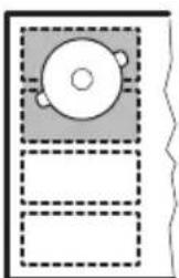
The flexible induction cooking area consists of four sections. The sections can be combined into two cooking zones with different size, or into one large cooking area.
The sides of the zones which operate together light up, and they are linked with shorter illuminated lines. You choose the combination of the sections by choosing the mode applicable to the size of the cookware you want to use. There are three modes: Standard (activated automatically when you activate the hob), Big Bridge and Max Bridge.

To set the heat setting use two left side control bars.
Switching between the modes
To switch between the modes use sensor field: 800
flowchart
graph TD
    A["Start"] --> B{Decision}
    B --> C["Process Step"]
    C --> D["Output Box 1"]
    C --> E["Output Box 2"]

When you switch between the modes the heat setting is set back to 0.
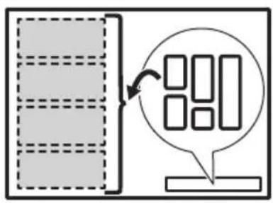
Diameter and position of the cookware
Choose the mode applicable to the size and the shape of the cookware. The cookware should cover the selected area as much as possible. Place the cookware centrally on the selected area!
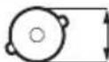
Place the cookware with the bottom diameter smaller than 160 mm centrally on a single section.
text_image
Diagram showing a checklist with three circular items and a checkmark, likely for checklist or selection.

100-160mm
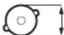
Place the cookware with the bottom diameter larger then 160 mm centrally between two sections.
natural_image
Simple line drawing of a room with two circular fixtures and a checkmark (no text or symbols)

160 mm
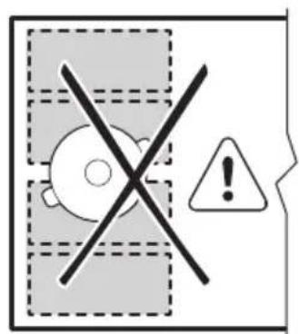
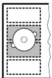
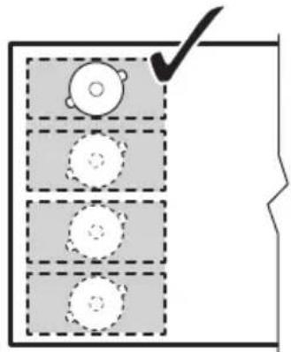
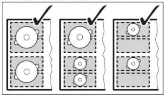
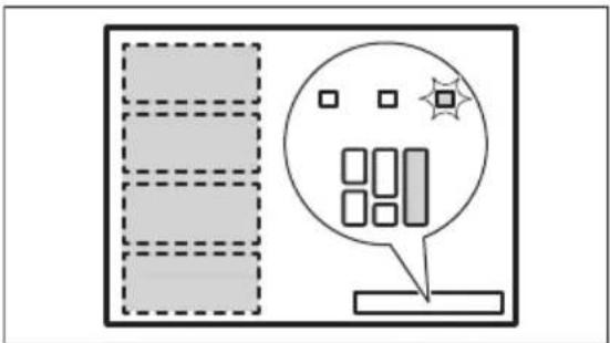
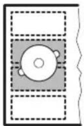
6.2 FlexiBridge Standard mode
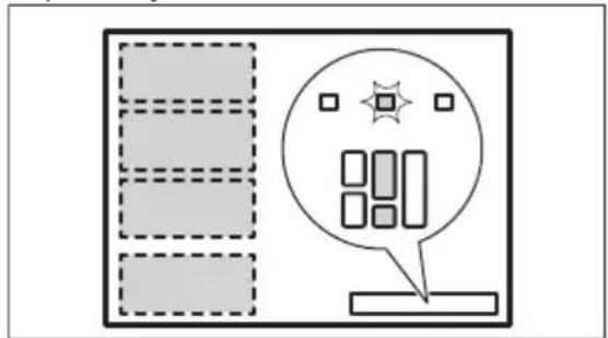
This mode is active when you activate the hob. It connects the sections into two separate cooking zones. The sides of the zones which operate together in this mode light up, and they are linked with shorter illuminated lines. You can set the heat setting for each zone separately. Use two left side control bars.
text_image
Diagram showing a grid layout with dashed boxes and a speech bubble containing icons, likely representing a UI or system interface.Correct cookware position:
text_image
Diagram showing three panels of a document with circular objects, each marked with a checkmark and dashed lines indicating selection or confirmation.Incorrect cookware position:
text_image
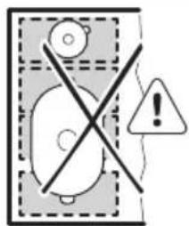
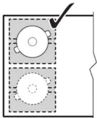
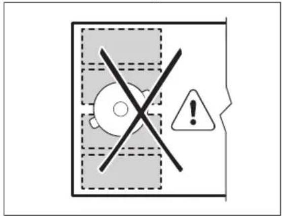
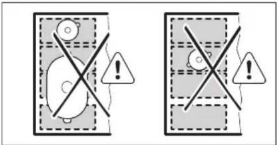
Warning sign with cross symbol and warning triangle, indicating no clear safety or hazard6.3 FlexiBridge Big Bridge mode
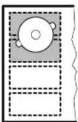
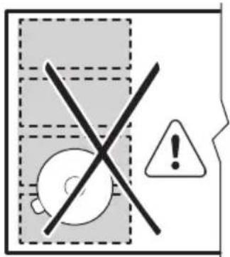
To activate the mode touch until you see the correct mode indicator This mode connects three rear sections into one cooking zone. The front section is not connected and operates as a separate cooking zone. You can set the heat setting for each zone separately. Use two left side control bars.
text_image
Diagram showing a window with dashed borders and a speech bubble containing rectangular blocks, likely representing a digital interface or layout.Correct cookware position:
To use this mode you have to place the cookware on the three connected sections. If you use cookware smaller than two sections the control bar blinks and after 2 minutes the zone switches off.
natural_image
Top-down diagram of a bathroom sink with a checkmark and mirror, no text or symbols presentIncorrect cookware position:
text_image
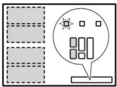
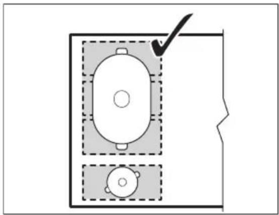
Safety warning sign showing crossed safety symbols and warning labels in two scenarios6.4 FlexiBridge Max Bridge mode
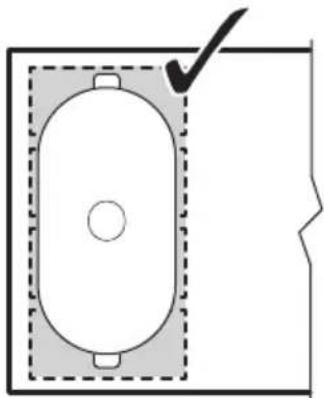
To activate the mode touch until you see the correct mode indicator This mode connects all sections into one cooking zone. To set the heat setting use any of the two control bars on the left side.
text_image
Diagram showing a grid with dashed boxes and a speech bubble containing rectangular blocks, alongside a star symbol.Correct cookware position:
To use this mode you have to place the cookware on the four connected sections. If you use cookware smaller than three sections the control bar blinks and after 2 minutes the zone switches off.
natural_image
Simple line drawing of a rectangular room with a central oval and two square corners, no text or symbols present.Incorrect cookware position:
text_image
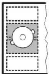
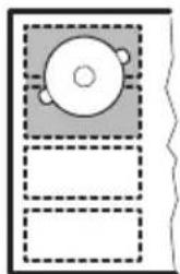
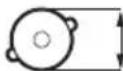
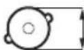
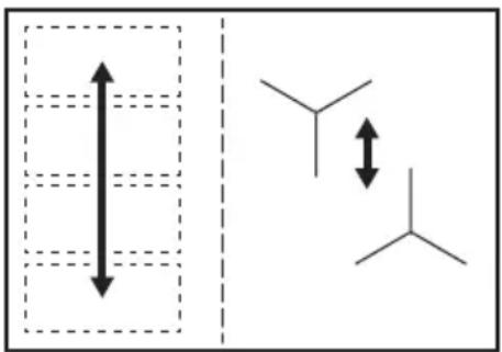
Warning sign with crossed-out circle and exclamation mark, indicating no intersection or explosion6.5 PowerSlide
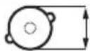
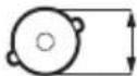
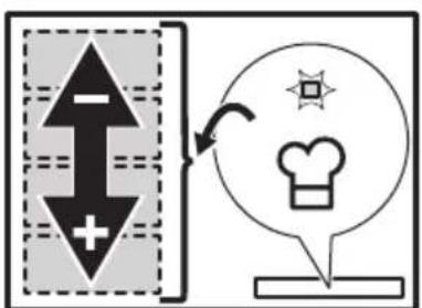
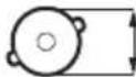
This function allows you to adjust the temperature by moving the cookware to a different position on the induction cooking area.
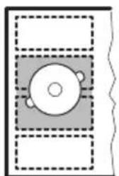
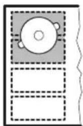
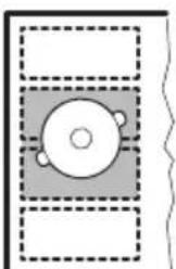
The function divides the induction cooking area into three areas with different heat settings. The hob detects the position of the cookware and adjust the heat setting corresponding with the position. You can place the cookware in the front, middle or rear position. If you place the cookware in the front you get the highest heat setting. To decrease it, move the cookware to middle or rear position.
flowchart
graph TD
    A["Downward Arrow"] --> B["Arrow to Right"]
    C["Upward Arrow"] --> D["Arrow to Left"]
    E["Speech Bubble"] --> F["Star Icon"]
    G["Speech Bubble"] --> H["Chef Icon"]

Use only one pot when you operate the function.
If you want to change the heat setting, lift up the cookware and place it on a different zone. Sliding the cookware can cause scratches and discolouration of the surface.
- 160 mm is the minimum bottom diameter of the cookware for this function.
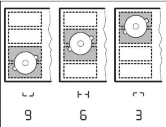
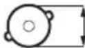
- If you place the pot in the front position, lights up on the control panel. The control bar displays the default heat setting 9
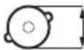
- If you place the pot in the middle position, lights up on the control panel. The control bar displays the default heat setting 6
- If you place the pot in the rear position, lights up on the control panel. The control bar displays the default heat setting 3
text_image
9 6 3- To change the default heat setting use left front control bar. You may change the default heat setting only if the function is active. You can change the heat settings for each position separately. The hob will remember your settings next time you activate the function.
Touch 🖱️ to activate the function.
The indicator comes on and the control bar displays the default heat setting.
To deactivate the function, touch 🏠
7. HINTS AND TIPS

WARNING!
Refer to Safety chapters.
7.1 Cookware

For induction cooking zones a strong electro-magnetic field creates the heat in the cookware very quickly.
Use the induction cooking zones with suitable cookware.
- The bottom of the cookware must be as thick and flat as possible.
- Ensure pan bases are clean and dry before placing on the hob surface.
- In order to avoid scratches, do not slide or rub the pot across the ceramic glass.
Cookware material
- correct: cast iron, steel, enamelled steel, stainless steel, multi-layer bottom (with a correct marking from a manufacturer).
- not correct: aluminium, copper, brass, glass, ceramic, porcelain.
Cookware is suitable for an induction hob if:
• water boils very quickly on a zone set to the highest heat setting.
- a magnet pulls on to the bottom of the cookware.
Cookware dimensions
- Induction cooking zones adapt to the dimension of the bottom of the cookware automatically.
- The cooking zone efficiency is related to the diameter of the cookware. The cookware with a diameter smaller than the minimum receives only a part of the power generated by the cooking zone.
- For both safety reasons and optimal cooking results, do not use cookware larger than indicated in "Cooking zones
specification". Avoid keeping cookware close to the control panel during the cooking session. This might impact the functioning of the control panel or accidentally activate hob functions.

Refer to "Technical data".
7.2 The noises during operation
If you can hear:
- crack noise: cookware is made of different materials (a sandwich construction).
- whistle sound: you use a cooking zone with a high power level and the cookware is made of different materials (a sandwich construction).
- humming: you use a high power level.
- clicking: electric switching occurs.
- hissing, buzzing: the fan operates.
The noises are normal and do not indicate any malfunction.
7.3 Öko Timer (Eco Timer)
To save energy, the heater of the cooking zone deactivates before the count down timer sounds. The difference in the operation time depends on the heat setting level and the length of the cooking operation.
7.4 Examples of cooking applications
The correlation between the heat setting of a zone and its consumption of power is not linear. When you increase the heat setting, it is not proportional to the increase of the consumption of power. It means that a cooking zone with the medium heat setting uses less than a half of its power.

The data in the table is for guidance only.
| Heat setting Use to: Time | (min) | Hints |
| 1 Keep cooked food warm. as neces- | sary | Put a lid on the cookware. |
| 1 - 2 Hollandaise sauce, melt: butter, choco-late, gelatine. | 5 - 25 Mix from time to time. | |
| 1 - 2 Solidify: fluffy omelettes, baked eggs. 10 - 40 Cook with a lid on. | ||
| 2 - 3 Simmer rice and milkbased dishes,heat up ready-cooked meals. | 25 - 50 Add at least twice as much liquid as rice, mix milk dishes halfway through the procedure. | |
| 3 - 4 Steam vegetables, fish, meat. 20 - 45 Add a couple of tablespoons of liquid. | ||
| 4 - 5 Steam potatoes. 20 - 60 Use max. 1⁄4 l of water for 750 g of po-tatoes. | ||
| 4 - 5 Cook larger quantities of food, stews and soups. | 60 - 150 Up to 3 l of liquid plus ingredients. | |
| 6 - 7 Gentle fry: escalope, veal cordon bleu,cutlets, rissoles, sausages, liver, roux,eggs, pancakes, doughnuts. | as neces-sary | Turn halfway through. |
| 7 - 8 Heavy fry, hash browns, loin steaks,steaks. | 5 - 15 Turn halfway through. | |
| 9 Boil water, cook pasta, sear meat (goulash, pot roast), deep-fry chips. | ||

Boil large quantities of water. PowerBoost is activated.
7.5 Hints and Tips for Hob ^2 Hood
When you operate the hob with the function:
- Protect the hood panel from direct sunlight.
- Do not spot halogen light on the hood panel.
- Do not cover the hob control panel.
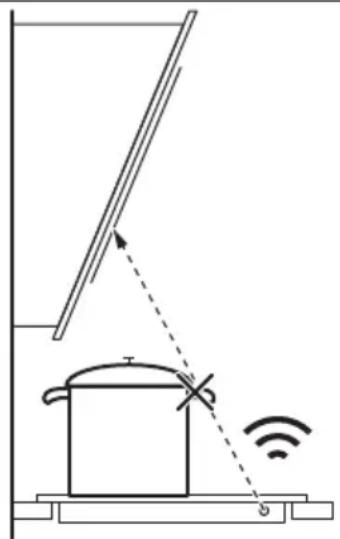
- Do not interrupt the signal between the hob and the hood (e.g. with the hand, a cookware handle or a tall pot). See the picture.
The hood in the picture is only exemplary.
natural_image
Diagram of a cooking pot with a diagonal pole and a Wi-Fi signal icon, no text or symbols present
Other remotely controlled appliances may block the signal. Do not use any such appliances near to the hob while Hob ^2 Hood is on.
Cooker hoods with the Hob ^2 Hood function To find the full range of cooker hoods which work with this function refer to our consumer
website. The AEG cooker hoods that work with this function must have the symbol 📞
8. CARE AND CLEANING

WARNING!
Refer to Safety chapters.
8.1 General information
- Clean the hob after each use.
• Always use cookware with a clean base. - Scratches or dark stains on the surface have no effect on how the hob operates.
- Use a special cleaner suitable for the surface of the hob.
- Use a special scraper for the glass.

The printing on the flexible induction cooking area may become dirty or change its colour from sliding the cookware. You can clean the area in a standard way.
8.2 Cleaning the hob
- Remove immediately: melted plastic, plastic foil, sugar and food with sugar, otherwise, the dirt can cause damage to the hob. Take care to avoid burns. Use a special hob scraper on the glass surface at an acute angle and move the blade on the surface.
- Remove when the hob is sufficiently cool: limescale rings, water rings, fat stains, shiny metallic discoloration. Clean the hob with a moist cloth and a non-abrasive detergent. After cleaning, wipe the hob dry with a soft cloth.
- Remove shiny metallic discoloration: use a solution of water with vinegar and clean the glass surface with a cloth.
9. TROUBLESHOOTING

WARNING!
Refer to Safety chapters.
9.1 What to do if...
Problem Possible cause Remedy
| You cannot activate or operate the hob. | The hob is not connected to an electrical supply or it is connected incorrectly. | Check if the hob is correctly connected to the electrical supply. |
| The fuse is blown. Make sure that the fuse is the cause of | the malfunction. If the fuse is blown again and again, contact a qualified electrician. | |
| You do not set the heat setting for 50 seconds. | Activate the hob again and set the heat setting in less than 50 seconds. | |
| You touched 2 or more sensor fields at the same time. | Touch only one sensor field. | |
| Pause operates. Refer to "Daily use". | ||
| Problem Possible cause Remedy | ||
| There is water or fat stains on the control panel. | Clean the control panel. | |
| You cannot select the maximum heat setting for one of the cooking zones.You cannot activate one of the cooking zones. | The other zones consume the maximum available power.Your hob works properly. | Reduce the heat setting of the other cooking zones connected to the same phase. Refer to "Power management". |
| An acoustic signal sounds and the hob deactivates.An acoustic signal sounds when the hob is deactivated. | You put something on one or more sensor fields. | Remove the object from the sensor fields. |
| The hob deactivates. You put something on the sensor field 1 | Remove the object from the sensor field. | |
| Residual heat indicator does not come on. | The zone is not hot because it operated only for a short time or the sensor is damaged. | If the zone operated sufficiently long to be hot, speak to an Authorised Service Centre. |
| Hob2Hood does not work. You covered the control panel. Remove the object from the control panel. | ||
| You use a very tall pot which blocks the signal. | Use a smaller pot, change the cooking zone or operate the hood manually. | |
| The sensor fields become hot. The cookware is too large or you put it too near to the controls. | Put large cookware on the rear zones, if possible. | |
| There is no sound when you touch the panel sensor fields. | The sounds are deactivated. Activate the sounds. Refer to "Daily use". | |
| The flexible induction cooking area does not heat up the cookware. | The cookware is in a wrong position on the flexible induction cooking area. | Place the cookware in the correct position on the flexible induction cooking area. The position of the cookware depends on the activated function or function mode. Refer to "Flexible induction cooking area". |
| The diameter of the bottom of the cookware is incorrect for the activated function or function mode. | Use cookware with a diameter applicable to the activated function or function mode. Refer to "Flexible induction cooking area". | |
| comes on. | Child Safety Device or Lock operates. | Refer to "Daily use". |
| The control bar blinks. There is no cookware on the zone or the zone is not fully covered. | Put cookware on the zone so that it fully covers the cooking zone. | |
| The cookware is unsuitable. Use suitable cookware. Refer to "Hints and tips". | ||
| The diameter of the bottom of the cookware is too small for the zone. | Use cookware with correct dimensions. Refer to "Technical data". | |
| FlexiBridge (Flexible Bridge) operates. One or more sections of the function mode which operates are not covered by the cookware. | Place the cookware on the correct number of sections of the function mode which operates or change the function mode. Refer to "Flexible induction cooking area". | |
| F comes on. | PowerSlide operates. Two pots are placed on the flexible induction cooking area. | Use only one pot. Refer to "Flexible induction cooking area". |
| E and a number come on. | There is an error in the hob. Deactivate the hob and activate it again after 30 seconds. If E comes on again, disconnect the hob from the electrical supply. After 30 seconds, connect the hob again. If the problem continues, speak to an Authorised Service Centre. | |
| You can hear a constant beep noise. | The electrical connection is incorrect. | Disconnect the hob from the electrical supply. Ask a qualified electrician to check the installation. |
9.2 If you cannot find a solution...
If you cannot find a solution to the problem yourself, contact your dealer or an Authorised Service Centre. Give the data from the rating plate. Make sure, you operated the hob correctly. If not the servicing by a service
technician or dealer will not be free of charge, also during the warranty period. The information about guarantee period and Authorised Service Centres are in the guarantee booklet.
10. TECHNICAL DATA
10.1 Rating plate
Model IPE84571IB PNC 949 597 491 00
Typ 62 D4A 21 AA 220 - 240 V / 400 V 2N 50 - 60 Hz
Induction 7.35 kW Made in Germany
Ser.Nr. 7.35 kW
AEG
10.2 Cooking zones specification
| Cooking zone Nominal power (maximum heat setting) [W] | PowerBoost [W] | PowerBoost maximum duration [min] | Cookware diameter [mm] |
| Middle rear 2300 3200 10 125 - 210 | |||
| Right front 1800 2800 10 145 - 180 | |||
| Flexible induction cooking area | 2300 3200 10 minimum 100 |
The power of the cooking zones can be different in some small range from the data in the table. It changes with the material and dimensions of the cookware.
For optimal cooking results use cookware no larger than the diameter in the table.
11. ENERGY EFFICIENCY
11.1 Product information\*
| Model identification IPE84571IB | ||
| Type of hob Built-In Hob | ||
| Number of cooking zones 2 | ||
| Number of cooking areas 1 | ||
| Heating technology Induction | ||
| Diameter of circular cooking zones (∅) Middle rear | Right front | 21.0 cm18.0 cm |
| Lenght (L) and width (W) of the cooking area Left L 41.8 cm | W 24.8 cm | |
| Energy consumption per cooking zone (EC electric cooking) | Middle rearRight front | 190.8 Wh / kg194.2 Wh / kg |
| Energy consumption of the cooking area (EC electric cooking) | Left 187.0 Wh / kg | |
| Energy consumption of the hob (EC electric hob) 189.2 Wh / kg | ||
* For European Union according to EU 66/2014. For Belarus according to STB 2477-2017, Annex A. For Ukraine according to 742/2019.
EN 60350-2 - Household electric cooking appliances - Part 2: Hobs - Methods for measuring performance
11.2 Energy saving
You can save energy during everyday cooking if you follow below hints.
- When you heat up water, use only the amount you need.
- If it is possible, always put the lids on the cookware.
-
Before you activate the cooking zone put the cookware on it.
-
Put the smaller cookware on the smaller cooking zones.
- Put the cookware directly in the centre of the cooking zone.
- Use the residual heat to keep the food warm or to melt it.
12. ENVIRONMENTAL CONCERNS
Recycle materials with the symbol .Put the packaging in relevant containers to recycle it. Help protect the environment and human health by recycling waste of electrical and
electronic appliances. Do not dispose of appliances marked with the symbol ☒ with the household waste. Return the product to
your local recycling facility or contact your municipal office.
TÄYDELLISIÄ TULOKSIA
1. ⚠TURVALLISUUSTIEDOT
How to install your AEG induction hob flush installation
4. TUOTEKUVAUS
text_image
Safety warning illustration showing a cooking pot with warning symbol and three safety symbols below.chemical
Chemical structure diagram showing a vertical double-headed arrow and two branched alkene groups attached to a central carbon chain5.12 Hob²Hood
natural_image
Pure diagram of a vertical panel with circular components and a checkmark, no text or symbols present
100-160mm
text_image
Diagram showing a grid layout with dashed boxes and a speech bubble containing rectangular blocks, alongside a star symbol and speech bubble.text_image
Diagram showing three panels of a grid with circular objects and checkmarks, likely illustrating a selection or counting exercise.text_image
Warning sign with crossed-out symbol and exclamation mark, indicating no clear safety or hazard6.3 FlexiBridge Big Bridge -tila
text_image
Diagram showing a grid layout with dashed boxes and a speech bubble containing a 8:10 display, alongside a star symbol.natural_image
Top-down diagram of a room layout with two furniture units and a checkmark indicating a detail (no text or symbols)text_image
Safety warning sign with crossed-out circle, warning triangle, and exclamation mark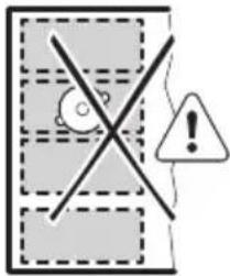
text_image
Warning sign with exclamation mark and warning symbol, indicating no liability or failure6.4 FlexiBridge Max Bridge -tila
text_image
Diagram showing a grid layout with dashed boxes and a speech bubble containing rectangular blocks, alongside a star symbol.natural_image
Simple line drawing of a rectangular room with a central circular area and a checkmark on the wall (no text or symbols)text_image
Warning sign with crossed-out circle, exclamation mark, and warning triangle6.5 PowerSlide
flowchart
graph TD
    A["Upward Arrow"] --> B["Downward Arrow"]
    B --> C["Arrow to Right"]
    C --> D["Speech Bubble with Teacher Icon"]
    D --> E["Back to Box"]

natural_image
Diagram of a simple electrical circuit with a pot, wires, and an antenna (no text or symbols)
| How to install your AEG induction hob flush installation |
4. DESCRIPTION DE L'APPAREIL
text_image
Safety warning illustration showing cooking process with a pot, warning symbol, and crossed-out devicechemical
Chemical structure diagram showing a vertical double-headed arrow and two branched alkene groups with double-headed arrows indicating resonance or equilibrium.5.12 Hob²Hood
natural_image
Pure diagram of a vertical stack of circular components with a checkmark and arrow, no text or symbols present.
100-160mm
text_image
Diagram showing a grid layout with dashed boxes and a speech bubble containing rectangular blocks, likely representing a digital interface or data display.text_image
Three-panel diagram showing a grid of four identical icons with checkmarks, likely for counting or matching exercises.text_image
Warning sign with crossed-out circle and exclamation mark, indicating no liability or failure6.3 FlexiBridge Mode Big Bridge
text_image
Diagram showing a window with dashed borders and a speech bubble containing rectangular blocks, likely representing a digital interface or layout.natural_image
Top-down diagram of a room layout with two furniture units and a checkmark indicating a detail (no text or symbols)text_image
Safety warning sign with crossed-out circle, triangle, and exclamation mark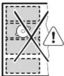
text_image
Warning sign with cross symbol and warning triangle, indicating no clear risk or absence6.4 FlexiBridge Mode Max Bridge
text_image
Diagram showing a grid layout with dashed boxes and a speech bubble containing rectangular blocks, alongside a speech bubble icon.natural_image
Simple line drawing of a rectangular room with a central oval and two square corners, no text or symbols present.text_image
Warning sign with crossed-out circle and exclamation mark, indicating no intersection or explosion6.5 PowerSlide
flowchart
graph TD
    A["Upward Arrow"] --> B["Downward Arrow"]
    B --> C["Circle Icon with Teacher's Hat"]
    C --> D["Arrow to Right"]
    style A fill:#000,stroke:#fff,color:#fff
    style B fill:#000,stroke:#fff,color:#fff
    style C fill:#fff,stroke:#000
    style D fill:#fff,stroke:#000

natural_image
Diagram of a simple electrical circuit with a pot, wires, and an antenna (no text or symbols)i
Gauche 187,0 Wh / kg
How to install your AEG induction hob flush installation

text_image
Safety warning illustration showing a cooking pot with warning symbol and three safety symbols below.chemical
Chemical structure diagram showing a vertical double-headed arrow and a branched alkene with double-headed arrows indicating resonance or bond formation.5.12 Hob²Hood
text_image
Diagram with geometric shapes and a speech bubble containing rectangular blocks, possibly representing a UI or layout concept.text_image
Three-panel diagram showing a grid of four identical circles with checkmarks, likely illustrating a counting or matching exercise.text_image
Warning sign with cross symbol and warning triangle, indicating no clear safety or hazard6.3 FlexiBridge Big Bridge-Modus
text_image
Diagram showing a grid layout with a circular icon containing a star and rectangular blocks, alongside a speech bubble with Chinese characters.natural_image
Top-down diagram of a room layout with two furniture units and a checkmark (no text or symbols)text_image
Safety warning sign with crossed-out circle, triangle, and exclamation mark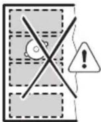
text_image
Warning sign with cross symbol, question mark, and warning triangle6.4 FlexiBridge Max Bridge-Modus
text_image
Diagram showing a grid layout with dashed boxes and a speech bubble containing rectangular blocks, alongside a star symbol.natural_image
Simple line drawing of a rectangular room with a central oval and two square corners, no text or symbols present.text_image
Warning sign with crossed-out circle and exclamation mark, indicating no clear safety or hazard6.5 PowerSlide
flowchart
graph TD
    A["Upward Arrow"] --> B["Downward Arrow"]
    B --> C["Circle Icon with Star, Chef's Hat, Speech Bubble"]
    C --> D["Speech Bubble"]
i
natural_image
Diagram of a cooking pot with a diagonal pole and a Wi-Fi signal icon, no text or symbols presenti
| How to install your AEG induction hob flush installation |
5.3 Utilizar as zonas de cozedura

CUIDADO!
text_image
Safety warning illustration showing a cooking pot with warning symbols and three safety instructions for cross-sections.chemical
Chemical structure diagram showing a vertical double-headed arrow and two separate branched alkene units with double-headed arrows indicating resonance or equilibrium.5.12 Hob²Hood
text_image
Diagram showing a checklist with three circular items and a checkmark, likely for checklist or selection.
100-160mm
natural_image
Simple diagram showing two circular components with a checkmark, enclosed in a dashed rectangle (no text or symbols)
160 mm
6.2 FlexiBridge modo normal
text_image
Diagram showing a digital display with a star and rectangular elements, alongside a grid of dashed boxes and a speech bubble containing '8:1'.text_image
Diagram showing three panels of a device with four circular components, each marked with a checkmark and dashed lines.text_image
Warning sign with cross symbol and warning triangle, indicating no clear safety or hazard6.3 FlexiBridge modo Big Bridge
natural_image
Simple line drawing of a room layout with dashed windows and a speech bubble containing rectangular blocks (no text or symbols)natural_image
Top-down architectural diagram of a room with an oval-shaped structure and a checkmark, enclosed in dashed boxes (no text or symbols)text_image
Safety warning sign showing crossed-out electrical hazard zones with warning symbols and warning labels6.4 FlexiBridge modo Max Bridge
natural_image
Simple line drawing of a room with a window and a speech bubble containing rectangular blocks (no text or symbols)natural_image
Simple line drawing of a rectangular room with a central circular element and a checkmark on the wall (no text or symbols)text_image
Warning sign with cross symbol and exclamation mark, indicating no liability or failure6.5 PowerSlide
flowchart
graph TD
    A["Upward Arrow"] --> B["Downward Arrow"]
    B --> C["Arrow to Right"]
    C --> D["Circle Icon with Teacher's Hat"]
    D --> E["Arrow to Down"]
    E --> F["Downward Arrow"]

natural_image
Simple line drawing of a CD or DVD player with no text, numbers, or symbolsLJ
9
natural_image
Simple diagram with a central circular element and two small protrusions, enclosed in a dashed rectangular border (no text or symbols)- 6
natural_image
Simple line drawing of a CD/DVD icon inside a square frame with dashed outlines (no text or symbols)r
3
text_image
Diagram illustrating a smart home control system with a pot, signal wave, and sensor placement
| How to install your AEG induction hob flush installation |  |
text_image
Safety warning illustration showing a cooking pot with warning symbol and three safety symbols below.chemical
Chemical structure diagram showing a vertical double-headed arrow and two branched alkene groups with double-headed arrows indicating resonance or equilibrium.5.12 Hob²Hood
natural_image
Simple diagram of a checklist with a checkmark and circular items, no text or symbols present.
100-160mm
natural_image
Simple diagram showing two circular components with a checkmark and dashed outlines, no text or symbols present.

160 mm
text_image
Diagram showing a grid with dashed boxes and a speech bubble containing rectangular blocks, alongside a star symbol.text_image
Diagram showing three groups of four identical circles with checkmarks, likely representing a counting or selection process.text_image
Warning sign with cross symbol and warning triangle, indicating no hazard or absence of a device6.3 FlexiBridge Modo Puente grande
text_image
Diagram showing a window with dashed borders and a speech bubble containing rectangular blocks, accompanied by a star symbol.natural_image
Top-down diagram of a bathroom sink with a checkmark and two circular fixtures, enclosed in a dashed rectangular frame (no text or symbols)text_image
Safety warning sign showing crossed warning symbols and warning labels in two safety zones6.4 FlexiBridge Modo Puente máx.
text_image
Diagram showing a grid with dashed boxes and a speech bubble containing rectangular blocks, alongside a star symbol.natural_image
Simple line drawing of a rectangular room with a central circular element and a checkmark on the wall (no text or symbols)text_image
Warning sign with crossed-out circle and exclamation mark, indicating no liability or failure6.5 PowerSlide
flowchart
graph TD
    A["Upward Arrow"] --> B["Downward Arrow"]
    B --> C["Circle Icon with Teacher's Hat"]
    C --> D["Arrow to Right"]
    style A fill:#000,stroke:#fff,color:#fff
    style B fill:#000,stroke:#fff,color:#fff
    style C fill:#fff,stroke:#000
    style D fill:#fff,stroke:#000

natural_image
Simple diagram of a circular object with two protrusions, enclosed in a dashed rectangle (no text or symbols)LJ
9
natural_image
Simple diagram with a central circle and two side handles, enclosed in dashed rectangular boxes (no text or symbols)- 6
natural_image
Simple diagram with a circular object and three small protrusions, enclosed in a dashed rectangle (no text or symbols)r
3
natural_image
Simple line drawing of a roof-mounted device with a roof, showing a beam, angle, and wireless signal icon (no text or symbols)8. MANTENIMIENTO Y LIMPIEZA

ADVERTENCIA!
How to install your AEG induction hob flush installation

4. PRODUKTBESKRIVNING
4.1 Hällens layout
text_image
3 1 1 2text_image
Safety warning illustration showing cooking process with a pot, warning symbol, and crosshair crossed out.chemical
Chemical structure diagram showing a vertical double-headed arrow and two branched alkene groups attached to a central carbon chain5.12 Hob²Hood
text_image
Diagram with geometric shapes and a speech bubble containing rectangular blocks, possibly representing a UI or layout concept.text_image
Diagram showing three groups of four identical circles with checkmarks, likely representing a counting or selection task.text_image
Warning sign with crossed-out circle and exclamation mark, indicating no clear safety or hazard6.3 FlexiBridge Big Bridge-läge
text_image
Diagram showing a grid layout with dashed boxes and a speech bubble containing rectangular blocks, including a star symbol.natural_image
Top-down diagram of a room layout with an oval object and two smaller circular objects, no text or symbols present.text_image
Safety warning sign with crossed-out circle, warning symbol, and exclamation mark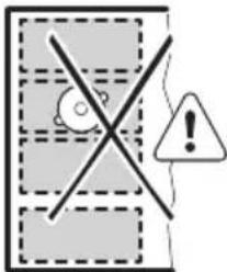
text_image
Warning sign with cross symbol, question mark, and warning triangle6.4 FlexiBridge Max Bridge-läge
text_image
Diagram showing a grid layout with dashed boxes and a speech bubble containing rectangular blocks, alongside a star symbol.natural_image
Simple line drawing of a rectangular room with a central circular element and a checkmark on the wall (no text or symbols)text_image
Warning sign with crossed-out circle and exclamation mark, indicating no intersection or explosion6.5 PowerSlide
flowchart
graph TD
    A["Vertical Arrow"] --> B["Horizontal Arrow"]
    C["Speech Bubble"] --> D["Arrow to Right"]
    E["Speech Bubble"] --> F["Speech Bubble"]
    G["Speech Bubble"] --> H["Speech Bubble"]

natural_image
Simple diagram with a central circular element and dashed rectangular outlines, no text or symbols present.LJ
9
natural_image
Simple diagram with a central circular element and two small protrusions, enclosed in dashed rectangular boxes (no text or symbols)- 6
natural_image
Simple line drawing of a room with a circular object on the wall and three empty boxes below (no text or symbols)r
3
natural_image
Diagram of a cooking pot with a lever and sensor signal, no text or symbols present