DTR180ZK - Scissors MAKITA - Free user manual and instructions
Find the device manual for free DTR180ZK MAKITA in PDF.

| Product Type | Cordless Rebar Tying Tool |
| Brand | Makita |
| Model | DTR180ZK |
| Overall Length | 317 mm |
| Net Weight (with battery) | 2.4 - 2.7 kg |
| Rated Voltage | 18 V DC |
| Compatible Battery | BL1815N, BL1820B, BL1830B, BL1840B, BL1850B, BL1860B |
| Compatible Charger | DC18RC, DC18RD, DC18RE, DC18SD, DC18SE, DC18SF, DC18SH, DC18WC |
| Tying Capacity (rebar) | Combinations of 2, 3 or 4 bars with diameters 10 to 35 mm |
| Wire Type | Annealed wire ø0.8 mm, polyester wire ø0.9 mm, galvanized wire ø0.8 mm (optional) |
| Number of ties per coil (approx.) | 65 to 75 ties depending on wire type |
| Sound pressure level (LpA) | 82 dB(A) |
| Sound power level (LWA) | 90 dB(A) |
| Vibration emission (tying) | 2.5 m/s² or less |
| Operating modes | Sequential mode (one tie per press) and continuous mode (holding the trigger) |
| Tying force adjustment | Yes, via rotary knob with digital display |
| Protection system | Overload, overheating and deep discharge protection |
| Battery charge indicator | LEDs on the battery |
| Safety devices | Trigger lock, loop guide open detection, automatic stop in case of error |
| Maintenance and cleaning | Cleaning the cutting section with wire brush or blower; can be disassembled for deep cleaning |
| Optional accessories | Wire guide B (EG), wire brush, telescopic handle |
Frequently Asked Questions - DTR180ZK MAKITA
User questions about DTR180ZK MAKITA
0 question about this device. Answer the ones you know or ask your own.
Ask a new question about this device
Download the instructions for your Scissors in PDF format for free! Find your manual DTR180ZK - MAKITA and take your electronic device back in hand. On this page are published all the documents necessary for the use of your device. DTR180ZK by MAKITA.
USER MANUAL DTR180ZK MAKITA
natural_image
Technical line drawing of a handheld electronic device with no visible text or symbols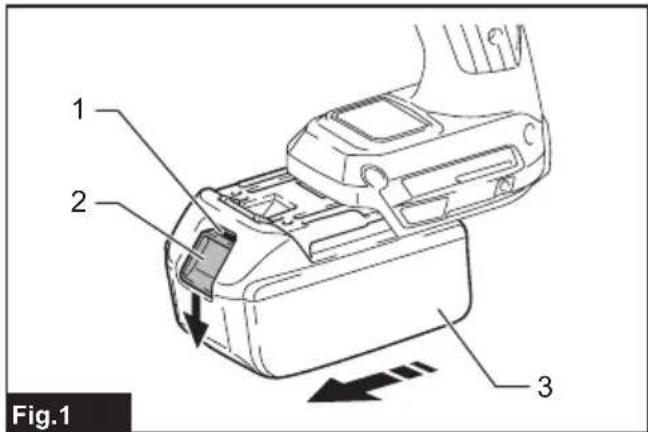


natural_image
Technical diagram of a mechanical component with labeled parts and directional arrow (no text or symbols beyond label)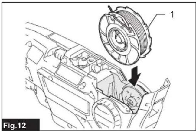
natural_image
Technical line drawing of a mechanical assembly with a coiled component and directional arrow (no text or symbols)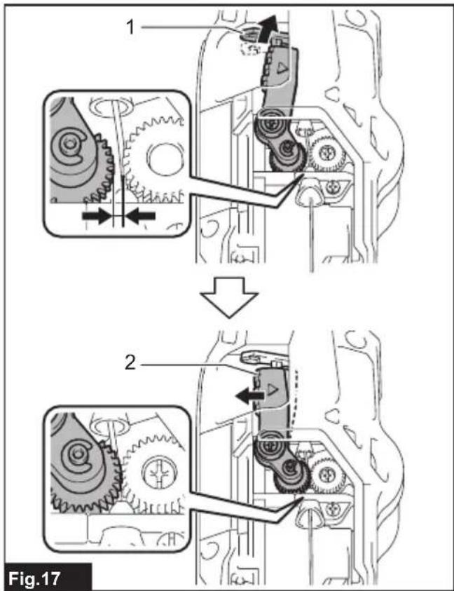
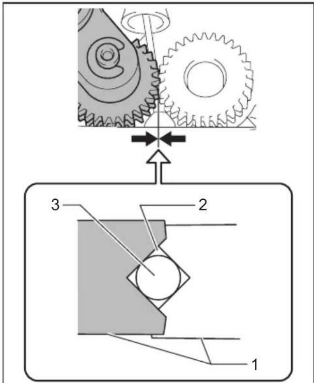
Fig.18
natural_image
Technical diagram of a car interior showing structural components and airflow direction (no text or symbols)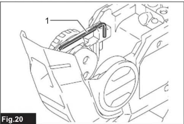
natural_image
Technical line drawing of a mechanical assembly with labeled component (no text or symbols beyond label)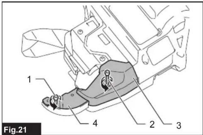
natural_image
3D mechanical part diagram labeled '1' with no visible text or symbols on the component itself

natural_image
Technical diagram of a mechanical component with a directional arrow indicating movement or force (no text or symbols present)
natural_image
Technical diagram of a mechanical assembly with rebar and pipe connections, showing a magnified inset of a component (no text or symbols present)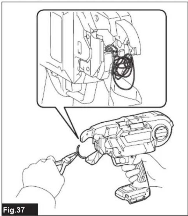
natural_image
Illustration of a hand using a power tool to adjust or install a mechanical component, with no visible text or symbols.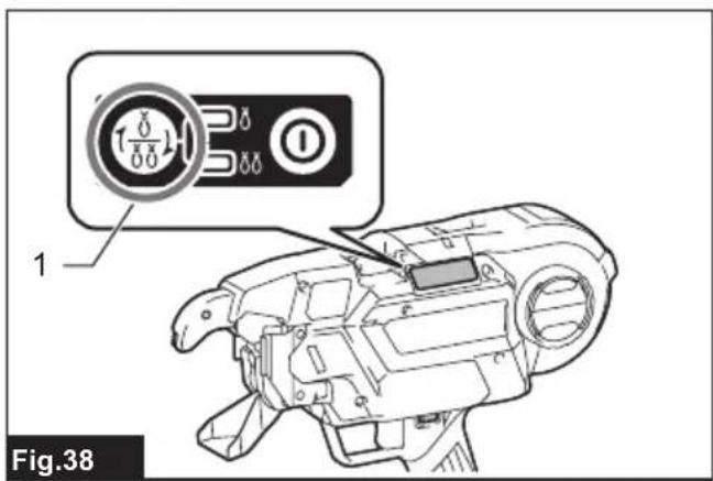
natural_image
Technical diagram of a mechanical assembly with rebar and pipe connections, showing a magnified inset of a component (no text or symbols present)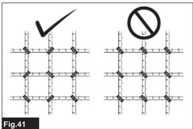
natural_image
Diagram of a rope knot tied between two intersecting pipes, labeled Fig.42 (no text or symbols on the diagram itself)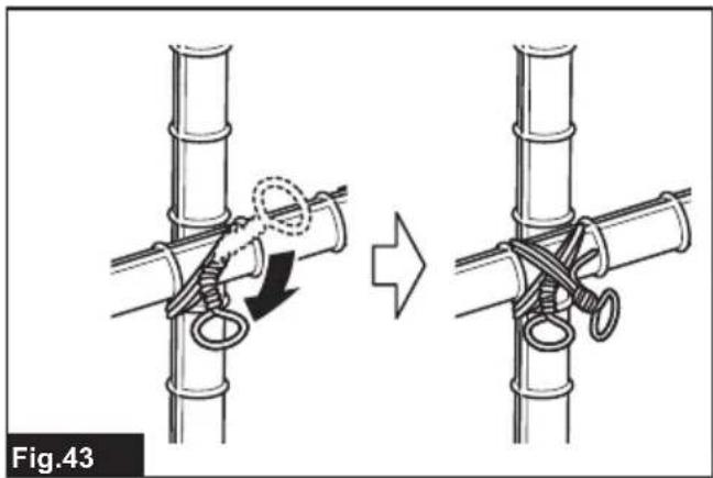
natural_image
Diagram showing two steps of tying a rope knot between two bamboo poles, with no text or symbols present.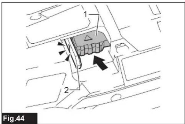
natural_image
Technical diagram of a mechanical component with labeled parts and directional arrow (no text or symbols beyond label)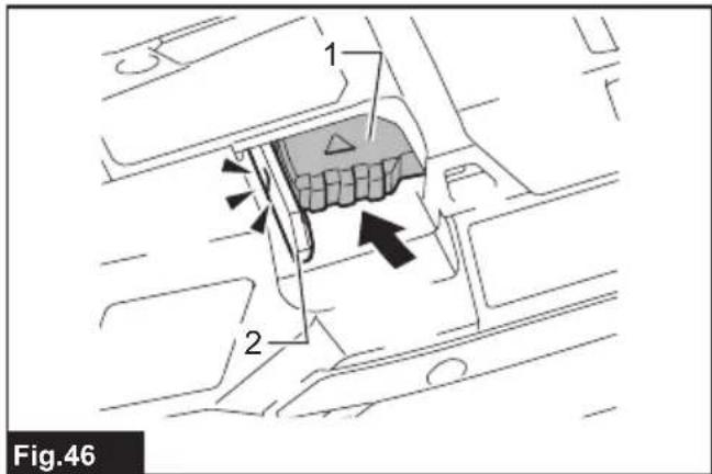
natural_image
Technical line drawing of a mechanical component with labeled parts (no text or symbols beyond label)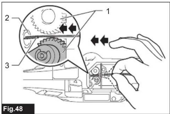
natural_image
Technical diagram of a car interior showing structural components and airflow direction (no text or symbols)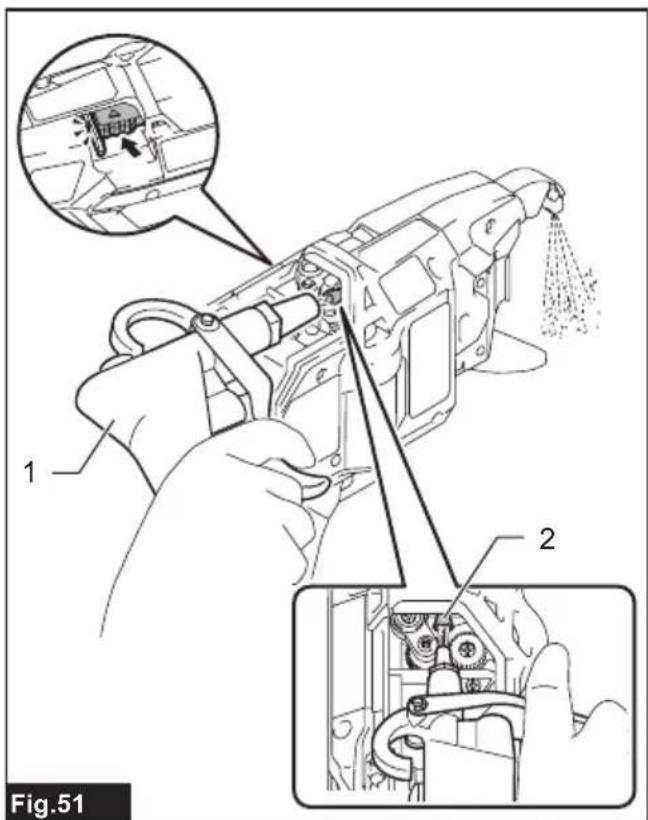
natural_image
Technical line drawing of a mechanical assembly with labeled component (no text or symbols beyond label)
natural_image
Technical line drawing of a mechanical bracket component (no text or symbols)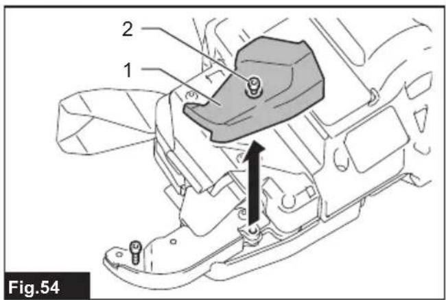

natural_image
Technical line drawing of a mechanical component with an arrow indicating direction (no text or symbols present)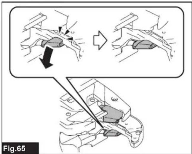
SPECIFICATIONS
| Model: DTR181 | ||
| Tie wire (Optional accessory) Annealing iron tie wire ø0.8 mm | ||
| Approximate number of ties per reel | Annealing iron tie wire Approximately 75 ties | |
| Poly coated tie wire Approximately 65 ties | ||
| Galvanized tie wire ^1 | Approximately 75 ties | |
| Overall length 317 mm | ||
| Rated voltage D.C. 18 V | ||
| Net weight 2.4 - 2.7 kg | ||
^*1 Available only when an optional wire guide B complete (EG) is installed in the arm.
- Due to our continuing program of research and development, the specifications herein are subject to change without notice.
- Specifications and battery cartridge may differ from country to country.
- The weight may differ depending on the attachment(s), including the battery cartridge. The lightest and heaviest combination are shown in the table.
Applicable battery cartridge and charger
| Battery cartridge BL1815N / BL1820B / BL1830B / BL1840B / BL1850B / BL1860B | |
| Charger DC18RC / DC18RD / DC18RE / DC18SD / DC18SE / DC18SF /DC18SH / DC18WC |
- Some of the battery cartridges and chargers listed above may not be available depending on your region of residence.
WARNING: Only use the battery cartridges and chargers listed above. Use of any other battery cartridges and chargers may cause injury and/or fire.
Combination of rebars that can be tied
Combination of 2 rebars
| #4 (13 mm) #5 | (16 mm) #6 (19 mm) #7 (22 mm) | ||
| #4 (13 mm) | √* | --- | |
| #5 (16 mm) | √* | √ | - |
| #6 (19 mm) | √ | √ | √ |
| #7 (22 mm) | √ | √ | √ |
| #8 (25 mm) | √ | √ | √ |
| #9 (29 mm) | √ | √ | √ |
| #10 (32 mm) | √ | √ | - |
| #11 (35 mm) | √ | --- |
* The combination is not designed for high tying strength.
Combination of 3 rebars
| #3 x #3 (10 mm x 10 mm) | #4 x #4 (13 mm x 13 mm) | #5 x #5 (16 mm x 16 mm) | |
| #3 (10 mm) | √* | √ | √ |
| #4 (13 mm) | √* | √ | √ |
| #5 (16 mm) | √ | √ | √ |
| #6 (19 mm) | √ | √ | √ |
| #7 (22 mm) | √ | √ | √ |
| #8 (25 mm) | √ | √ | √ |
* The combination is not designed for high tying strength.
Combination of 4 rebars
| #3 x #3 (10 mm x 10 mm) #4 x | #4 (13 mm x 13 mm) | |
| #3 x #3 (10 mm x 10 mm) | √ | √ |
| #4 x #4 (13 mm x 13 mm) | √ | √ |
| #5 x #5 (16 mm x 16 mm) | √ | √ |
NOTICE: If there is a gap between rebars or if the tool is used at an incorrect orientation, the rebars may not be able to be tied.
Symbols
The followings show the symbols which may be used for the equipment. Be sure that you understand their meaning before use.


Ni-MH Li-ion
Only for EU countries
Due to the presence of hazardous components in the equipment, waste electrical and electronic equipment, accumulators and batteries may have a negative impact on the environment and human health. Do not dispose of electrical and electronic appliances or batteries with household waste!
In accordance with the European Directive on waste electrical and electronic equipment and on accumulators and batteries and waste accumulators and batteries, as well as their adaptation to national law, waste electrical equipment, batteries and accumulators should be stored separately and delivered to a separate collection point for municipal waste, operating in accordance with the regulations on environmental protection.
This is indicated by the symbol of the crossed-out wheeled bin placed on the equipment.
Intended use
The tool is intended for tying rebars.
Noise
The typical A-weighted noise level determined according to EN60745-2-18:
Sound pressure level ( L_pA ): 82 dB (A)
Sound power level (LWA): 90 dB (A)
Uncertainty (K) : 3 dB (A)
NOTE: The declared noise emission value(s) has been measured in accordance with a standard test method and may be used for comparing one tool with another.
NOTE: The declared noise emission value(s) may also be used in a preliminary assessment of exposure.
WARNING: Wear ear protection.
⚠ WARNING: The noise emission during actual use of the power tool can differ from the declared value(s) depending on the ways in which the tool is used especially what kind of workpiece is processed.
⚠ WARNING: Be sure to identify safety measures to protect the operator that are based on an estimation of exposure in the actual conditions of use (taking account of all parts of the operating cycle such as the times when the tool is switched off and when it is running idle in addition to the trigger time).
Vibration
The vibration total value (tri-axial vector sum) determined according to EN60745-2-18:
Work mode: Tying metal rod
Vibration emission ( a_h ): 2.5 m/s ^2 or less
Uncertainty (K) : 1.5 m/s²
NOTE: The declared vibration total value(s) has been measured in accordance with a standard test method and may be used for comparing one tool with another.
NOTE: The declared vibration total value(s) may also be used in a preliminary assessment of exposure.
⚠ WARNING: The vibration emission during actual use of the power tool can differ from the declared value(s) depending on the ways in which the tool is used especially what kind of workpiece is processed.
⚠ WARNING: Be sure to identify safety measures to protect the operator that are based on an estimation of exposure in the actual conditions of use (taking account of all parts of the operating cycle such as the times when the tool is switched off and when it is running idle in addition to the trigger time).
Declarations of Conformity
For European countries only
The Declarations of conformity are included in Annex A to this instruction manual.
SAFETY WARNINGS
General power tool safety warnings
⚠ WARNING Read all safety warnings, instructions, illustrations and specifications provided with
this power tool. Failure to follow all instructions listed below may result in electric shock, fire and/or serious injury.
Save all warnings and instructions for future reference.
The term "power tool" in the warnings refers to your mains-operated (corded) power tool or battery-operated (cordless) power tool.
Cordless rebar tying tool safety warnings
- Never point the tool toward a person. Never put your hands or feet close to the tool tip. If you accidentally operate the tool while it is touching someone, it will lead to an unexpected accident.
- Do not load wire while the power to the tool is turned on. Otherwise, you may get caught in the wire and injured.
- Do not use the tool without closing the reel cover. Otherwise, the wire reel may come off and cause an accident.
- Be sure to check that the diameters of rebars to be tied are within the tool capacity before beginning work.
- Wear clothes that have close-fitting hemlines and sleeves. Do not work with a towel or other object wrapped around your neck. Otherwise, they may get caught in the rotating part and cause an accident.
- Be sure to inspect the following points before using the tool.
- Check that no parts are damaged
- Check that no bolts are loose
- Check that safety devices operate normally
- If any abnormalities are found, stop using the tool immediately. Do not repair the tool by yourself. Ask your local Makita Service Center for repairs. If the tool is used in an incomplete state, an accident may occur.
- When installing the battery cartridge, be sure to lock the trigger and do not place your finger on the trigger. Incorrect operation may cause an accident.
- When tying rebars, exercise care not to move them. If rebars move due to tying, you may be injured.
- Do not touch the wires during the wire tying process. Otherwise, you may get caught in the wire and injured.
- Do not bring your hands close to the tying point during the wire tying process. Otherwise, you may get caught in the wire and injured.
- Hold the grip of the tool firmly during the wire tying process. Otherwise, your wrist may be twisted or your body may be pulled, which may result in an injury.
- Do not move to the next tying point until the current wire tying process is completed. Otherwise, you may be injured.
- Pay attention to the end of the wire during the
wire tying process. Otherwise, your hand may be caught by the end of the wire, and you may be injured.
- Do not touch the contact plate during the wire tying process. If you need to touch the contact plate, be sure to lock the trigger, or turn the power switch off and remove the battery cartridge. Otherwise, you may be injured.
- When you have completed the wire tying process, pull the tool up vertically. Otherwise, the arm may be caught on rebars, which may cause an accident.
- Be careful not to drop, bump, or hit the tool. If a strong impact is applied prior to the tool being used, make sure that the tool is not damaged or cracked, and that the safety devices operate normally. Otherwise, an accident may occur.
-
If any of the following phenomena occur, lock the trigger, turn the power switch off, and remove the battery cartridge from the tool. If the tool operates incorrectly, an accident may occur.
-
If an operating sound is heard as soon as the battery cartridge is mounted.
- If overheating or abnormal smells or noises are detected.
- When you are taking measures in response to the error display. (Ask your local Makita Service Center for repairs.)
- When loading or unloading a wire reel.
- When you move while holding the tool during work.
- When you do not use the tool.
- When you inspect or adjust the tool.
-
When you remove a stranded wire.
-
When working on scaffolding, always stabilize it and work using a posture that will ensure you maintain your balance. If scaffolding is unstable, an accident may occur.
- When working on a roof or similar locations, move in a forward direction while working so that you can see where you are going. If you move in a backward direction while working, you may lose your footing and cause an accident.
- If you are working in a highly elevated location, ensure that no one is below you, and pay attention to ensure you do not drop any tools while working. Dropping the tool may cause an accident.
- Do not use the tool for any work other than wire tying. Otherwise, an accident may occur.
- Always use Makita's genuine wires. If wires are not used for a long period of time, they may rust. Do not use rusted wires. Otherwise, they may cause an accident.
- After tying, check for wire breakage due to excessive twisting. If any wires are broken, tying strength will be lost. Adjust the tying strength, and tie the rebars again.
- Securely place the arm against the rebars. If it is not securely positioned, a clearance will be created between the rebars, and tying strength will be compromised.
Important safety instructions for battery cartridge
- Before using battery cartridge, read all instructions and cautionary markings on (1) battery charger, (2) battery, and (3) product using battery.
- Do not disassemble or tamper with the battery cartridge. It may result in a fire, excessive heat, or explosion.
- If operating time has become excessively shorter, stop operating immediately. It may result in a risk of overheating, possible burns and even an explosion.
- If electrolyte gets into your eyes, rinse them out with clear water and seek medical attention right away. It may result in loss of your eyesight.
- Do not short the battery cartridge:
(1) Do not touch the terminals with any conductive material.
(2) Avoid storing battery cartridge in a container with other metal objects such as nails, coins, etc.
(3) Do not expose battery cartridge to water or rain.
A battery short can cause a large current flow, overheating, possible burns and even a breakdown.
- Do not store and use the tool and battery cartridge in locations where the temperature may reach or exceed 50 °C (122 °F).
- Do not incinerate the battery cartridge even if it is severely damaged or is completely worn out. The battery cartridge can explode in a fire.
- Do not nail, cut, crush, throw, drop the battery cartridge, or hit against a hard object to the battery cartridge. Such conduct may result in a fire, excessive heat, or explosion.
- Do not use a damaged battery.
- The contained lithium-ion batteries are subject to the Dangerous Goods Legislation requirements.
For commercial transports e.g. by third parties, forwarding agents, special requirement on packaging and labeling must be observed.
For preparation of the item being shipped, consulting an expert for hazardous material is required.
Please also observe possibly more detailed national regulations.
Tape or mask off open contacts and pack up the battery in such a manner that it cannot move around in the packaging.
- When disposing the battery cartridge, remove it from the tool and dispose of it in a safe place. Follow your local regulations relating to disposal of battery.
- Use the batteries only with the products specified by Makita. Installing the batteries to non-compliant products may result in a fire, excessive heat, explosion, or leak of electrolyte.
- If the tool is not used for a long period of time, the battery must be removed from the tool.
- During and after use, the battery cartridge may
take on heat which can cause burns or low temperature burns. Pay attention to the handling of hot battery cartridges.
- Do not touch the terminal of the tool immediately after use as it may get hot enough to cause burns.
- Do not allow chips, dust, or soil stuck into the terminals, holes, and grooves of the battery cartridge. It may cause heating, catching fire, burst and malfunction of the tool or battery cartridge, resulting in burns or personal injury.
- Unless the tool supports the use near high-voltage electrical power lines, do not use the battery cartridge near high-voltage electrical power lines. It may result in a malfunction or breakdown of the tool or battery cartridge.
- Keep the battery away from children.
SAVE THESE INSTRUCTIONS.
⚠️CAUTION: Only use genuine Makita batteries. Use of non-genuine Makita batteries, or batteries that have been altered, may result in the battery bursting causing fires, personal injury and damage. It will also void the Makita warranty for the Makita tool and charger.
Tips for maintaining maximum battery life
- Charge the battery cartridge before completely discharged. Always stop tool operation and charge the battery cartridge when you notice less tool power.
- Never recharge a fully charged battery cartridge. Overcharging shortens the battery service life.
- Charge the battery cartridge with room temperature at 10 °C - 40 °C ( 50 °F - 104 °F ). Let a hot battery cartridge cool down before charging it.
- When not using the battery cartridge, remove it from the tool or the charger.
- Charge the battery cartridge if you do not use it for a long period (more than six months).
FUNCTIONAL DESCRIPTION
⚠️CAUTION: Always be sure that the tool is switched off and the battery cartridge is removed before adjusting or checking function on the tool.
Installing or removing battery cartridge
⚠️ CAUTION: Always switch off the tool before installing or removing of the battery cartridge.
CAUTION: Hold the tool and the battery cartridge firmly when installing or removing battery cartridge. Failure to hold the tool and the battery cartridge firmly may cause them to slip off your hands and result in damage to the tool and battery cartridge and a personal injury.
▶ Fig.1: 1. Red indicator 2. Button 3. Battery cartridge
To remove the battery cartridge, slide it from the tool while sliding the button on the front of the cartridge.
To install the battery cartridge, align the tongue on the battery cartridge with the groove in the housing and slip it into place. Insert it all the way until it locks in place with a little click. If you can see the red indicator as shown in the figure, it is not locked completely.
CAUTION: Always install the battery cartridge fully until the red indicator cannot be seen. If not, it may accidentally fall out of the tool, causing injury to you or someone around you.
CAUTION: Do not install the battery cartridge forcibly. If the cartridge does not slide in easily, it is not being inserted correctly.
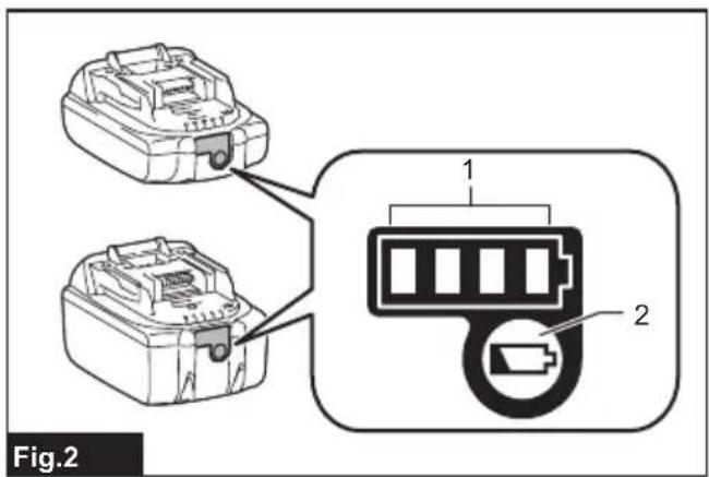
Indicating the remaining battery capacity
Only for battery cartridges with the indicator
Press the check button on the battery cartridge to indicate the remaining battery capacity. The indicator lamps light up for a few seconds.
▶ Fig.2: 1. Indicator lamps 2. Check button
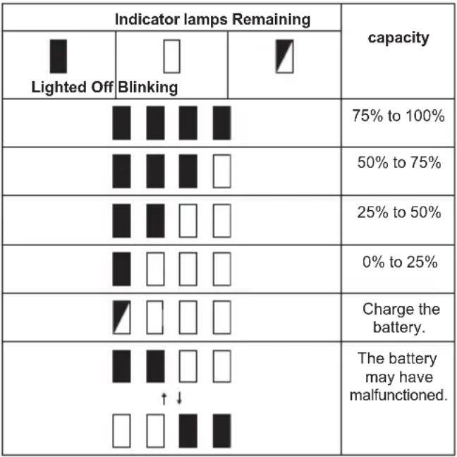 |
NOTE: Depending on the conditions of use and the ambient temperature, the indication may differ slightly from the actual capacity.
NOTE: The first (far left) indicator lamp will blink when the battery protection system works.
Tool / battery protection system
The tool is equipped with a tool/battery protection system. This system automatically cuts off power to the motor to extend tool and battery life. The tool will automatically stop during operation if the tool or battery is placed under one of the following conditions:
Overload protection
When the tool or battery is operated in a manner that causes it to draw an abnormally high current, the tool automatically stops and the corresponding error number is displayed on the display panel. In this situation, turn the tool off and stop the application that caused the tool to become overloaded. Then turn the tool on to restart.
Overheat protection
When the tool or battery is overheated, the tool stops automatically and the corresponding error number is displayed on the display panel. In this case, let the tool and battery cool before turning the tool on again.
Overdischarge protection
When the battery capacity is not enough, the tool stops automatically and the corresponding error number is displayed on the display panel. In this case, remove the battery from the tool and charge the battery.
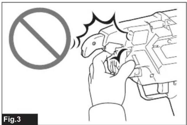
Main power switch
⚠CAUTION: When you turn the power on, never bring your limbs or face close to the binding or rotating parts of the tool tip. Otherwise, you may be injured.
⚠️CAUTION: When the power is turned on, never touch the binding or rotating parts of the tool tip. Otherwise, you may be injured.
⚠️CAUTION: Before inserting the battery cartridge, be sure to release your fingers from the switch trigger and lock the trigger. If you insert the battery cartridge while the switch trigger is being pulled, it may cause an accident if the wire tying process is accidentally carried out.
▶ Fig.3
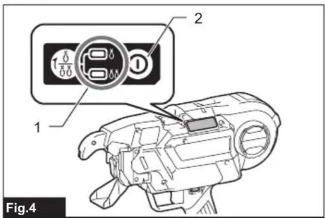
When you press the power button, the power turns on and the tying mode lamp lights up. In order for the tool to adjust its initial position, it operates temporarily. When adjustment has completed, the tool stops automatically. When you press the power button again, the power turns off and the tying mode lamp goes out.
▶ Fig.4: 1. Tying mode lamp 2. Power button
NOTE: The tool has an auto power-off function. If the switch trigger is not pulled for 10 minutes, the tool is automatically turned off to reduce battery power consumption.
NOTE: To restart the tool, turn the power on again.
Mode switching button
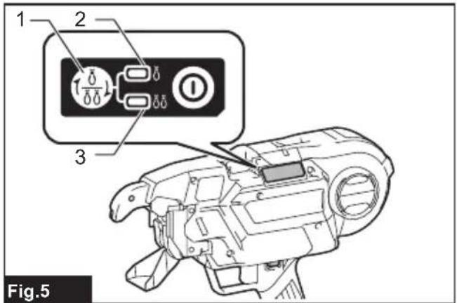
When the power is turned on and the tying mode lamp is lit, you can select the single actuation mode or the continuous actuation mode via the mode switching button. When you turn the power on again, the tool starts in the mode that was most recently selected.
▶ Fig.5: 1. Mode switching button 2. Single actuation mode 3. Continuous actuation mode
Switch action
WARNING: Before installing the battery cartridge into the tool, always check to see that the switch trigger actuates properly and returns to the "OFF" position when released.
CAUTION: When not operating the tool, depress the trigger-lock button from inside to lock the switch trigger in the OFF position.
▶ Fig.6: 1. Switch trigger 2. Trigger-lock button
To prevent the switch trigger from accidentally pulled, the trigger-lock button is provided. To start the tool, depress the trigger-lock button from A side and pull the switch trigger. Release the switch trigger to stop. After use, press in the trigger-lock button from B side.
When you pull the switch trigger, the tool performs the next sequential operations as follows, and the tool stops automatically.
- Feed the wire.
- Cut the wire.
- The hook holds and twists the wire.
- The hook returns to the original position.
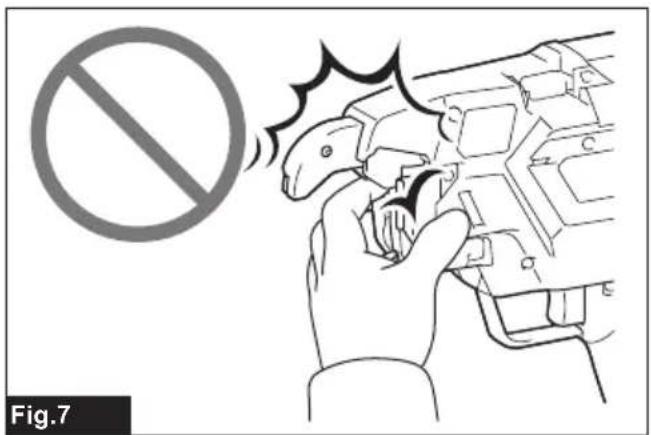
Tying strength setting
CAUTION: Be sure to lock the trigger before starting the adjustment. When you turn the power on, never bring your limbs or face close to the binding or rotating parts of the tool tip. Otherwise, you may be injured.
▶ Fig.7
You can set the tying strength by adjusting the tying strength adjusting button. Tying strength is shown on the display panel.
▶ Fig.8: 1. Tying strength adjusting button 2. Display panel
If the wire is broken off, tying strength will be lost. After tying, check the twisted portion for breakage.
If the wire is broken off, adjust the tying strength using the tying strength adjusting button, and tie the rebars again.
Remaining battery notification
When the battery voltage drops below the required level, the tool will stop operating, an error tone will sound, and the number "4" will appear on the display panel. The error tone will continue to sound until the power is turned off.
NOTE: If the ambient temperature is extremely low, the error tone may sound even when the battery contains sufficient power.
ASSEMBLY
⚠️CAUTION: Always be sure that the tool is switched off and the battery cartridge is removed before carrying out any work on the tool.
Loading the tie wire (wire reel)
⚠CAUTION: Before mounting or dismounting tie wires and accessories, be sure to turn the power off, lock the trigger, and remove the battery cartridge. Failure to do so may cause an accident.
NOTICE: Using wires other than Makita's genuine tie wires may cause the tool to malfunction.
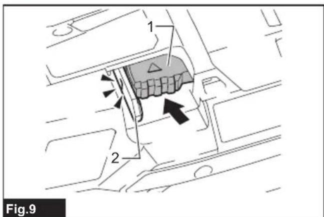
- Push the release lever, and lock it with the lock lever.
▶ Fig.9: 1. Release lever 2. Lock lever
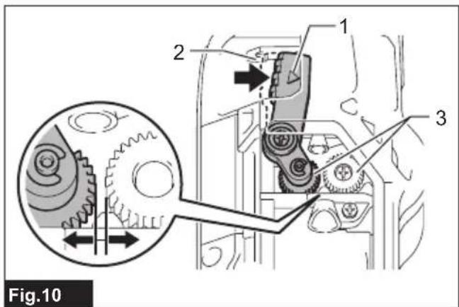
When you push the release lever, a gap is created between the left and right feed gears.
▶ Fig.10: 1. Release lever 2. Lock lever 3. Feed gears
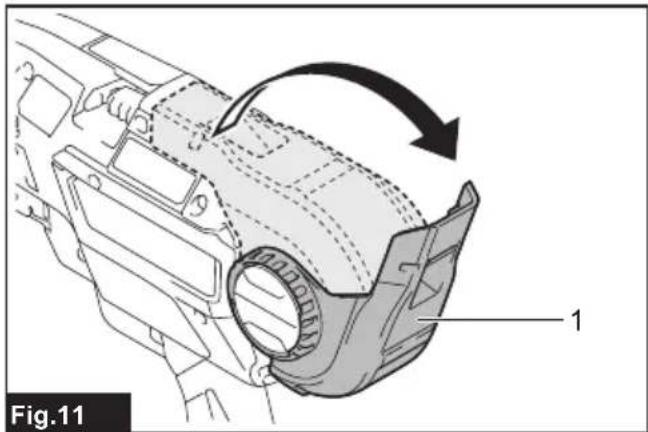
- Open the reel cover.
▶ Fig.11: 1. Reel cover
- Mount the wire reel on the tool in the orientation shown in the figure.
▶ Fig.12: 1. Wire reel
NOTICE: Be sure to mount the wire reel in the orientation shown in the figure. If it is mounted the other way around, the wire will be released and may be twisted.
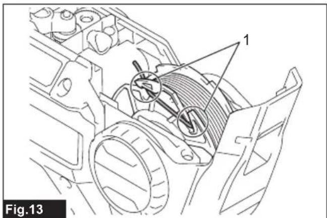
- Unhook the wire tip from the hook of reel.
▶ Fig.13: 1. Hook
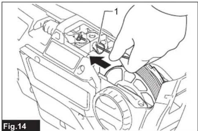
- Make the tip of the wire straight, and pass the wire through the guide.
▶ Fig.14: 1. Guide
NOTE: If the tip of the wire is bent when it is passed through the guide, the wire may become jammed in the tool.
NOTE: If you force the wire when trying to pass it through the guide, the wire may become jammed.
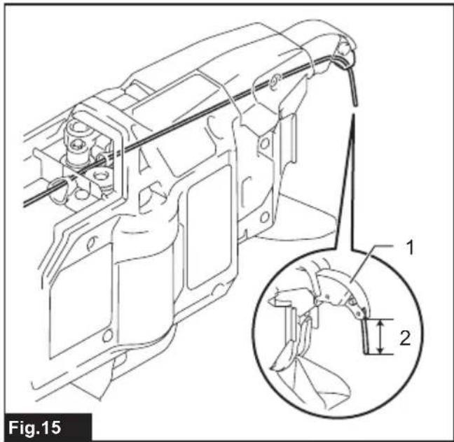
- Pull the wire out approximately 10 mm from the tip of the arm.
▶ Fig.15: 1. Arm 2. Approximately 10 mm
NOTICE: If the length of the pulled-out wire is insufficient, the wire may be broken off when tied, or tying strength may be compromised due to insufficient wraps.
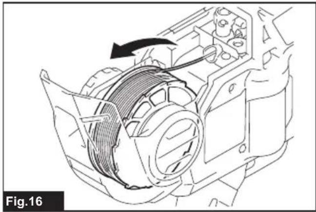
- Rewind the wire to eliminate its slack.
▶ Fig.16
- Release the lock lever. The release lever returns, and the wire is held by the left and right gears.
▶ Fig.17: 1. Lock lever 2. Release lever
▶ Fig.18: 1. Gear 2. Path of the wire 3. Wire
NOTICE: When the lock lever is released and when the left and right gears mesh with each other, the grooves in the gears form a space. This space becomes the path for the wire. Make sure that the wire is passed through this path.
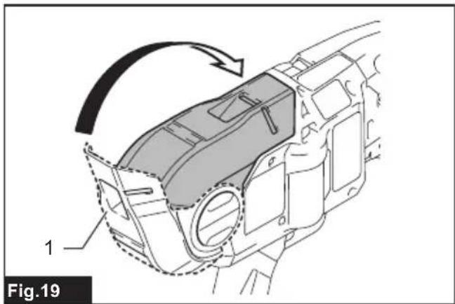
- Close the reel cover.
▶ Fig.19: 1. Reel cover
Replacing wire guide B
Optional accessory
The wire guide B (in silver color) in the arm can be replaced with an optional wire guide B (EG) (in black color) according to the type of tying wire to use.
Find the right combination in the following table. Then replace the standard equipped wire guide B with an optional wire guide B (EG) if necessary.
| Standard equipped wire guide B complete (silver) | Optional wire guide B complete (black) | |
| Annealing iron tie wire | √ | √ |
| Poly coated tie wire - | √ | |
| Galvanized tie wire - | √ |
— : The combination is not valid.
- Loosen bolts A and B using the hex wrench included in the tool package.
▶ Fig.20: 1. Hex wrench
▶ Fig.21: 1. Bolt A 2. Bolt B 3. Contact plate cover 4. Standard equipped wire guide B (silver)
NOTICE: Do not forcibly remove any bolts that cannot be removed using the hex wrench.
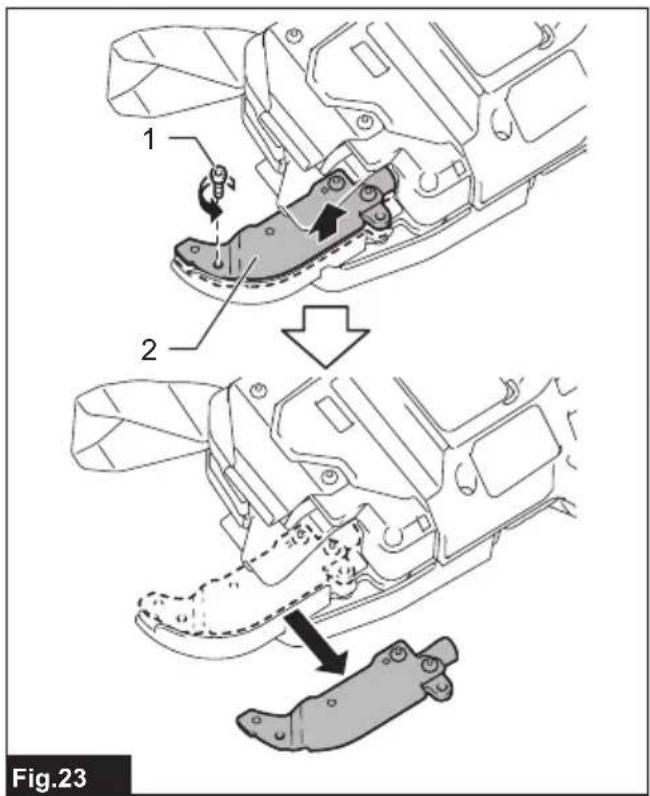
- Pull the contact plate cover up in the direction of the arrow and remove it. Bolt B will be removed at the same time.
▶ Fig.22: 1. Contact plate cover 2. Bolt B
- Remove bolt A, and remove the standard equipped wire guide B (silver).
▶ Fig.23: 1. Bolt A 2. Standard equipped wire guide B (silver)
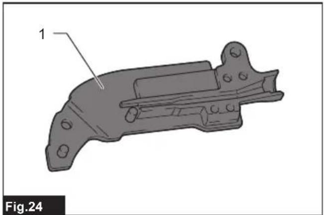
- Replace the standard equipped wire guide B (in silver color) with an optional wire guide B (EG) (in black color).
▶ Fig.24: 1. Optional wire guide B (EG) (in black color).
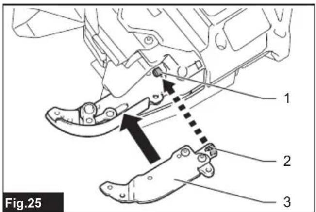
- Align the pipe of the tool with the groove inside the optional wire guide B (EG) (black), and assemble them.
▶ Fig.25: 1. Pipe 2. Groove 3. Optional wire guide B (EG) (black).
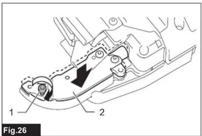
- Fix the optional wire guide B (EG) (black) by temporarily tightening bolt A.
▶ Fig.26: 1. Bolt A 2. Optional wire guide B (EG) (black).
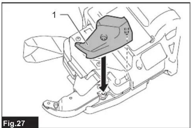
- Install the contact plate cover in the direction of the arrow.
▶ Fig.27: 1. Contact plate cover
- Fix the optional wire guide B (EG) (black) and contact plate cover securely by tightening bolt A and bolt B.
▶ Fig.28: 1. Optional wire guide B (EG) (black). 2. Contact plate cover 3. Bolt A 4. Bolt B
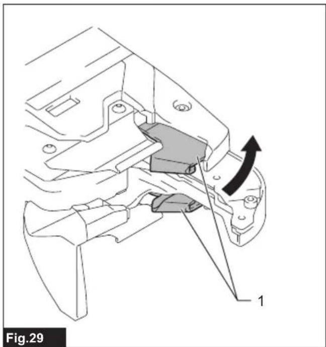
- After assembling, confirm that the contact plate can move as shown in the figure.
▶ Fig.29: 1. Contact plate
NOTE: If the contact plate is caught, press it as shown in the figure.
▶ Fig.30
OPERATION
Checking before work
CAUTION: If the tool has a safety mechanism-related problem, do not use it. If you continue to use it, an accident may occur.
Before using the tool, make sure that the safety mechanism operates normally. If the tool operates without the safety mechanism operating, stop using the tool immediately. Ask your local Makita Service Center for repairs.
Checking the trigger-lock
The tool has the trigger-lock to prevent the tool from operating when you do not intend to use it. Lock the trigger and confirm that the switch trigger cannot be pulled.
Checking the curl guide
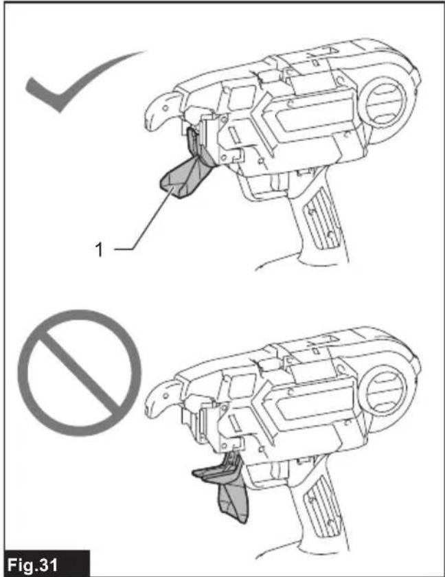
To prevent the operator from touching the binding or rotating parts of the tool tip by mistake, the tool will not operate even if the switch trigger is pulled while the curl guide is opened. When the operator releases their finger from the switch trigger and closes the curl guide, the tool can operate.
▶ Fig.31: 1. Curl guide
Checkout for curl guide open/close detection
Remove the tie wire, check the tool operation according to the following steps, and make sure that the tool does not start if the curl guide is open.
-
Turn the power off, and leave the curl guide open.
-
Turn the power on.
If the tool will not operate and if the value "2" is shown
on the display panel, the state of the tool is normal. Turn the power off, and close the curl guide.
If the tool operates and if no error is shown on the display panel, the state of the tool is abnormal. Stop using the tool immediately, and ask your local Makita Service Center for repairs.
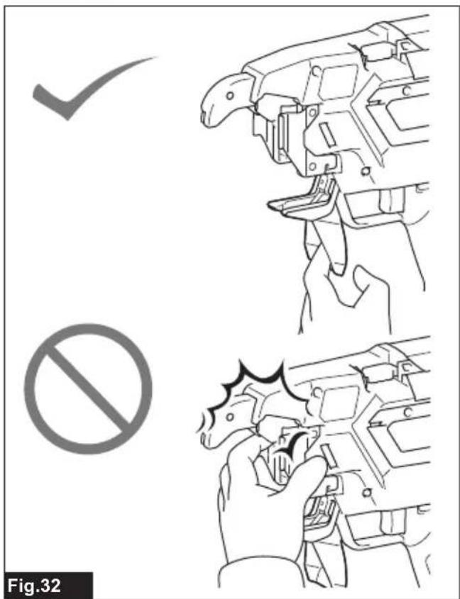
CAUTION: If you open the curl guide and turn the power on to check the interlock, hold the curl guide as shown in the figure. Never bring your limbs or face close to the binding or rotating parts of the tool tip. Otherwise, you may be injured.
▶ Fig.32
Tying work
CAUTION: Before inserting the battery cartridge, be sure to release your fingers from the switch trigger and lock the trigger. If you insert the battery cartridge while the switch trigger is being pulled, it may cause an accident if the wire tying process is accidentally carried out.
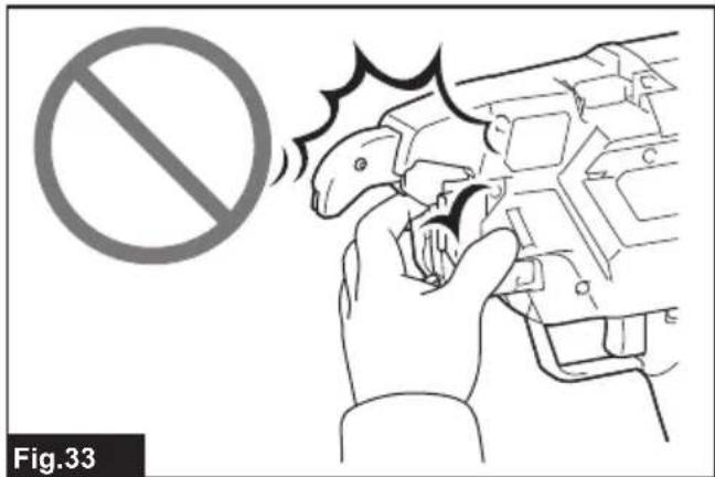
CAUTION: When you turn the power on, never bring your limbs or face close to the binding or rotating parts of the tool tip. Otherwise, you may be injured.
⚠️ CAUTION: When the power is turned on, never touch the binding or rotating parts of the tool tip. Otherwise, you may be injured.
▶ Fig.33
Preparation before work
- Make sure that the battery cartridge is removed and the trigger is locked.
- Insert the battery cartridge into the tool, and turn the power on. When you turn the power on, the wire is cut automatically.
NOTICE: Make sure that the tying mode lamp lights up when the power is turned on. If it does not light up, recharge the battery.
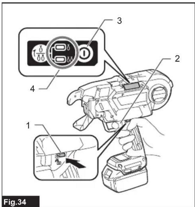
- Release the trigger lock.
▶ Fig.34: 1. Trigger-lock button 2. Switch trigger 3. Power button 4. Tying mode lamp
Single actuation mode
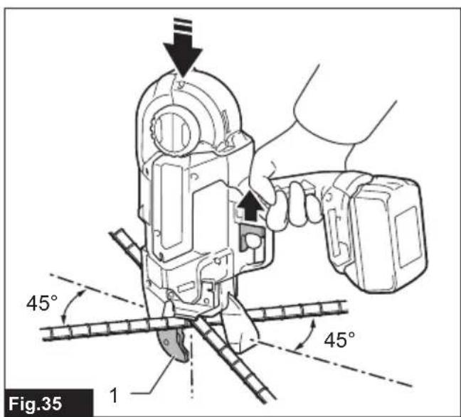
- Push the arm firmly against the tying point. Make sure to place the tool vertically over the rebars and press the arm on the tying point at a 45^ angle against the crossed rebars.
▶ Fig.35: 1. Arm
- Pull the switch trigger once.
- The wire is fed and cut automatically.
- The hook holds and twists the wire, then returns to the original position after the wires have been tied.
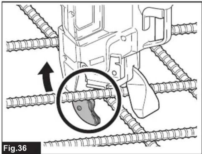
- After tying, be careful not to hook the arm on the rebars, and then pull the tool up.
▶ Fig.36
⚠️CAUTION: If the wire has clung to the binding part of the tool tip, turn the power of the tool off. Lock the trigger, remove the battery cartridge, and remove the wire using tools such as nippers or pliers.
▶ Fig.37
Continuous actuation mode
- Switch the tool mode from the single actuation mode to the continuous actuation mode using the mode switching button.
▶ Fig.38: 1. Mode switching button - Release the trigger lock.
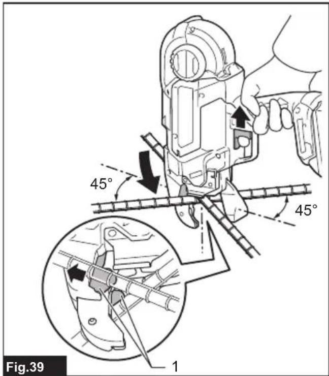
- While pulling the switch trigger, push the tool vertically against the rebars, and press the arm against the point where the rebars cross at a 45-degree angle. Press the contact plate firmly against the tying point.
The wire will be tied.
▶ Fig.39: 1. Contact plate
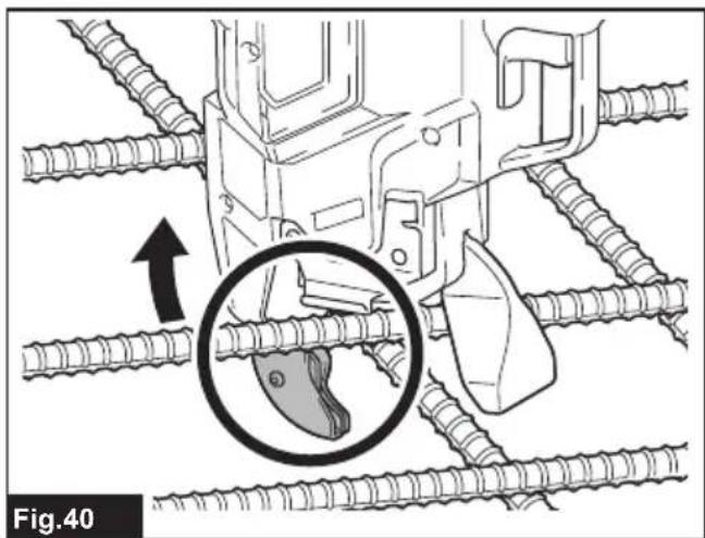
- After tying, be careful not to hook the arm on the rebars, and then pull the tool up.
▶ Fig.40
Cautions on working
- If you move the arm from the tying position during the wire tying process, the wire will get stuck on the hook, which may lead to incorrect tying.
- Keep pressing the tool against the rebars until the wire tying process is completed.
- Do not move to the next tying point until the current wire tying process is completed.
- The tool tip rotating part (hook) twists the wire during the wire tying process. Hold the grip firmly so that your body is not pulled by the tool.
- Do not touch the wires during the wire tying process.
- If you are repeating the wire tying processes in the single actuation mode, fully release your finger from the switch trigger. Then, continue to operate the switch trigger.
- If you pull the switch trigger when there is no tie wire left, an error is displayed. Replace with a new tie wire and restart the tool.
Tying tips
- Tilt the tool at a 45^ angle against the crossed rebars, and tie the wire in alternate orientations as shown in the figure.
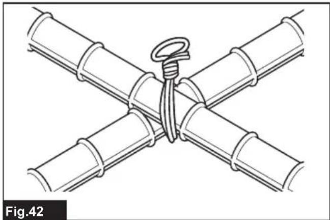
▶ Fig.41 - Tie the wire onto the flat (with no unevenness) sections of crossed rebars.
▶ Fig.42 - If tying strength is insufficient, change the tying orientation and perform tying twice so that tying strength increases.
▶ Fig.43
NOTICE: When you make the second tie, bend the tail of the first tie before making the second tie. Otherwise, the wire may be repelled a second time. It may cling to the tool tip, and the hook may be damaged.
Replacing the tie wires
⚠️ CAUTION: When you replace the wire, be sure to turn the power off, lock the trigger, and remove the battery cartridge. Failure to do so may cause an accident.
- When wire has been used up, an error tone will sound and error "1" will be displayed.
- Lock the trigger, turn the power off, and remove the battery cartridge.
- Push the release lever, and lock it with the lock lever.
▶ Fig.44: 1. Release lever 2. Lock lever
- Remove the wire reel from the tool.
NOTE: When wire has been used up normally, approximately 20 cm of the wire remains wound on the reel. In this state, replace the wire reel with a new one.
If it is difficult to remove the wire reel from the tool, follow the steps below.
- Insert the battery cartridge into the tool, and turn the power on. The tool feeds the wire and cuts it automatically.
- Lock the trigger, turn the power off, and remove the battery cartridge.
- Remove the wire breaks using tools such as nippers or pliers.
MAINTENANCE
CAUTION: Always be sure that the tool is switched off and the battery cartridge is removed before attempting to perform inspection or maintenance.
NOTICE: Never use gasoline, benzine, thinner, alcohol or the like. Discoloration, deformation or cracks may result.
To maintain product SAFETY and RELIABILITY, repairs, any other maintenance or adjustment should be performed by Makita Authorized or Factory Service Centers, always using Makita replacement parts.
Cleaning the cutter section
When the tool is used, dust and wire particles may become adhered to the cutter section. In such a case, clean the cutter section according to the following procedure. The cleaning should be done each time you use up a box of reel. (50 pcs.)
Using the wire brush
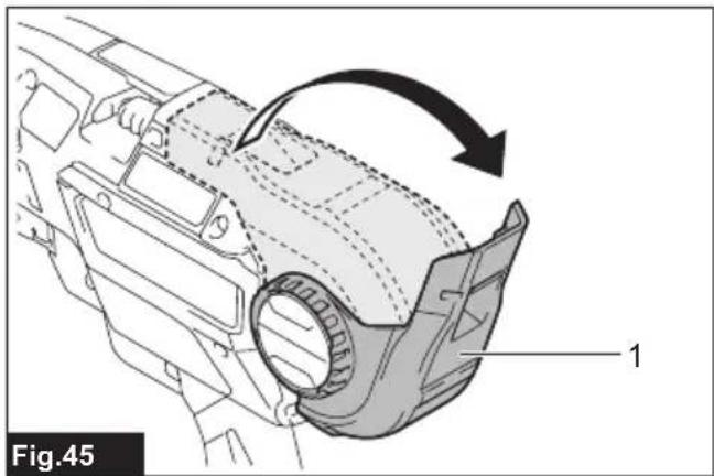
- Open the reel cover.
▶ Fig.45: 1. Reel cover
- Push the release lever, and lock it with the lock lever.
▶ Fig.46: 1. Release lever 2. Lock lever
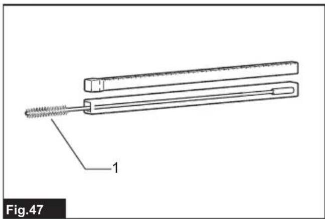
- Pass the wire brush through the guide.
When inserting the wire brush, hold it short and push it into the guide little by little.
▶ Fig.47: 1. Wire brush
▶ Fig.48: 1. Gear 2. Guide 3. Wire brush
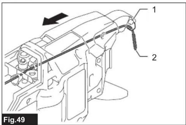
- Push in the wire brush until its top end comes out from the tip of the arm. And then pull out the wire brush. This action is enough with one time.
▶ Fig.49: 1. Arm 2. Wire brush
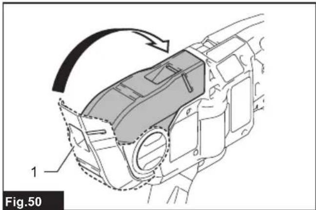
- Close the reel cover.
▶ Fig.50: 1. Reel cover
Using the air duster gun
Open the reel cover, push the release lever, and lock it with the lock lever. Then bring the air duster gun close to the guide and blow the air. Make sure the air comes from the tip of the arm.
▶ Fig.51: 1. Air duster gun 2. Guide
Cleaning with disassembly
If the cutter section is clogged or a wire is caught in it, disassemble the parts and clean them.
Disassembling and cleaning
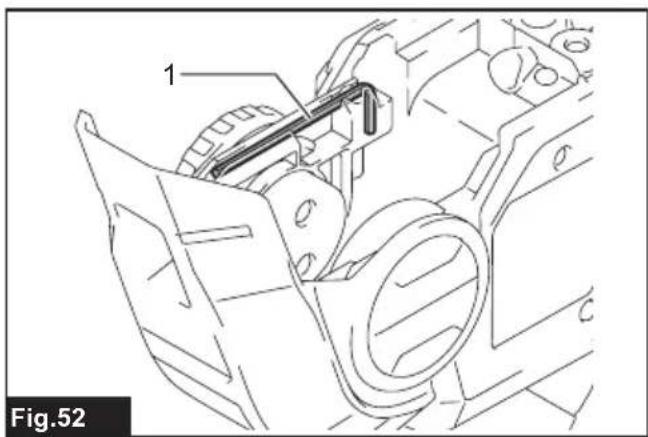
- Loosen bolts A and B using the hex wrench included in the tool package.
▶ Fig.52: 1. Hex wrench
▶ Fig.53: 1. Bolt A 2. Bolt B 3. Contact plate cover 4. Wire guide B
NOTICE: Do not forcibly remove any bolts that cannot be removed using the hex wrench.
- Pull the contact plate cover up in the direction of the arrow and remove it. Bolt B will be removed at the same time.
▶ Fig.54: 1. Contact plate cover 2. Bolt B
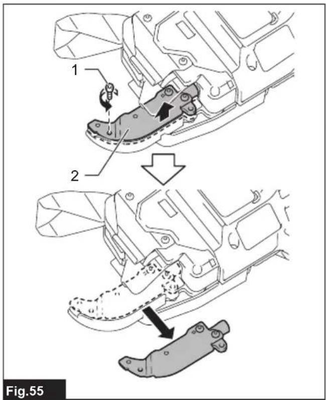
3. Remove bolt A, and remove wire guide B.
▶ Fig.55: 1. Bolt A 2. Wire guide B
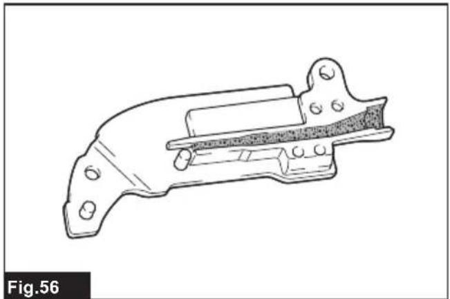
4. Turn wire guide B over and clean its inside.
▶ Fig.56
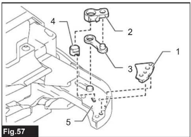
5. Remove top plate, cutter B, link arm A and cutter A from arm plate A. Then, clean them.
▶ Fig.57: 1. Top plate 2. Cutter B 3. Link arm A 4. Cutter A 5. Arm plate A
Assembling
When cleaning is finished, assemble the parts according to the following procedure.
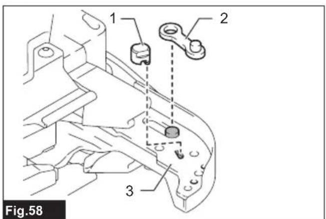
- Install cutter A and link arm A to fit the shape of arm plate A.
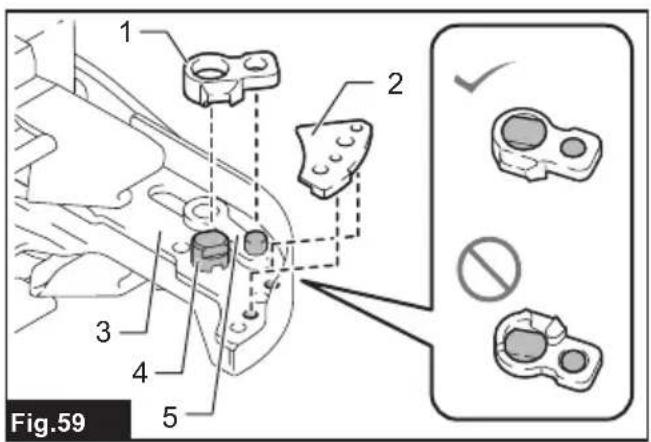
▶ Fig.58: 1. Cutter A 2. Link arm A 3. Arm plate A - Install cutter B and the top plate onto arm plate A. (Install cutter B on cutter A and link arm A.)
▶ Fig.59: 1. Cutter B 2. Top plate 3. Arm plate A 4. Cutter A 5. Link arm A
NOTICE: Face the projection of cutter B downward, and install the cutter as shown in the figure.
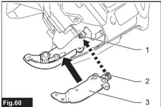
- Align the pipe of the tool with the groove inside the wire guide B, and assemble them.
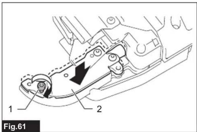
▶ Fig.60: 1. Pipe 2. Groove 3. Wire guide B - Fix wire guide B by temporarily tightening bolt A.
▶ Fig.61: 1. Bolt A 2. Wire guide B - Install the contact plate cover in the direction of the arrow.
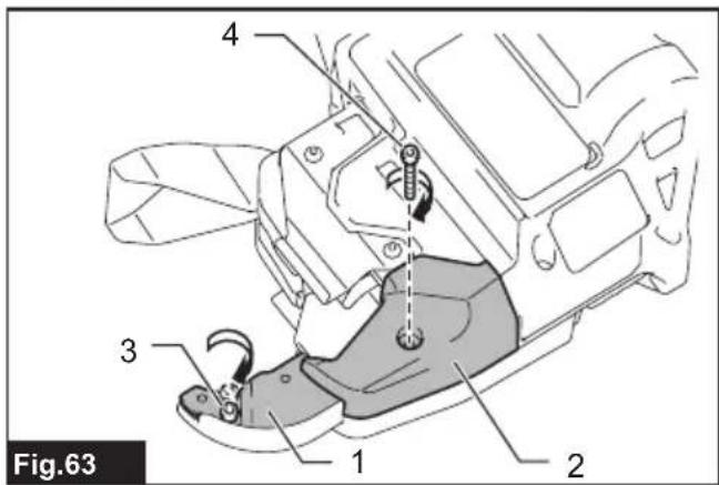
▶ Fig.62: 1. Contact plate cover - Fix wire guide B and contact plate cover securely by tightening bolt A and bolt B.
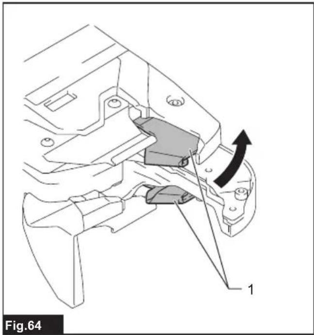
▶ Fig.63: 1. Wire guide B 2. Contact plate cover 3. Bolt A 4. Bolt B - After assembling, confirm that the contact plate can move as shown in the figure.
▶ Fig.64: 1. Contact plate
NOTE: If the contact plate is caught, press it as shown in the figure.
▶ Fig.65
Error display and error tone
⚠️CAUTION: During inspection, be sure to lock the trigger, turn the power off, and remove the battery cartridge. Failure to do so may cause an accident.
⚠️CAUTION: When you turn the power on, never bring your limbs or face close to the binding or rotating parts of the tool tip. Otherwise, you may be injured.
⚠️CAUTION: When the power is turned on, never touch the binding or rotating parts of the tool tip. Otherwise, you may be injured.
⚠️CAUTION: If an error tone sounds, or if the tool malfunctions, immediately stop using the tool.
Error tone and display
If an error occurs, an error tone will sound, and an error number will be shown on the display panel. Refer to the following table and take appropriate actions. If the error persists, ask Makita Authorized Service Centers for repairs.
| Display Symptom Possible cause Solution | |||
| 1 The tool stops operating. The wire has been used | up. Load new tie wire. | ||
| Tie wire is not loaded. Load tie wire. | |||
| Wire feeding has failed. Check the orientation of the tie wire.Unload the tie wire, and load it again.Clean the path of wire. | |||
| 2 The tool stops operating. The curl guide is open. Close the curl guide. | |||
| 3 The tool does not perform the tying process in continuous actuation mode. | The contact plate is caught. Release the contact plate from being caught. | ||
| 4 The tool does not start.The tool stops operating. | The battery has been discharged.The temperature of the battery cartridge is abnormally high. | Recharge the battery.Cool the battery cartridge down.Replace the battery cartridge with a recharged one. | |
| 5 The tool stops operating. The motor is overloaded. | Determine the cause of the | obstruction of the motor rotation and solve the problem. | |
| Motor failure | |||
| 6 The tool stops operating. The temperature of the tool is abnormally high. | Cool the tool down. | ||
| 7 The tool does not start.The tool stops operating. | Tool failure Ask Makita Authorized Service Centers for repairs. | ||
OPTIONAL ACCESSORIES
⚠️CAUTION: These accessories or attachments are recommended for use with your Makita tool specified in this manual. The use of any other accessories or attachments might present a risk of injury to persons. Only use accessory or attachment for its stated purpose.
If you need any assistance for more details regarding these accessories, ask your local Makita Service Center.
- Tie wire
• Wire guide B complete (EG) - Wire brush
- Extension handle
- Makita genuine battery and charger
NOTE: Some items in the list may be included in the tool package as standard accessories. They may differ from country to country.
SPÉCIFICATIONS
▶ Fig.29: 1. Plaque de contact
▶ Fig.64: 1. Plaque de contact
▶ Abb.52: 1. Inbusschlüssel
A WAARSCHUWING: Draag gehoorbescherming.
VEILIGHEIDSWAAR- SCHUWINGEN
▶ Fig.15: 1. Arm 2. Ongeveer 10 mm
▶ Fig.58: 1. Knipper A 2. Verbindingsarm A
OPTIONELE ACCESSOIRES
▶ Fig.20: 1. Chave hexagonal
▶ Fig.21: 1. Perno A 2. Perno B 3. Tampa da placa de contacto 4. Guia de fio B (prateada) equipada de série