GF120mmF4 R LM OIS WR Macro - Camera FUJIFILM - Free user manual and instructions
Find the device manual for free GF120mmF4 R LM OIS WR Macro FUJIFILM in PDF.
| Technical Specifications | FUJIFILM GF120mmF4 R LM OIS WR macro lens with a maximum aperture of f/4, minimum focusing distance of 0.4 m, and a magnification factor of 1:2. |
|---|---|
| Usage | Ideal for macro, portrait, and nature photography, offering excellent image quality thanks to its advanced optical construction. |
| Maintenance and Repair | Regularly clean the lenses with a soft cloth, avoid shocks and moisture. In case of issues, contact an authorized FUJIFILM service center. |
| Safety | Do not expose the lens to extreme temperatures or excessive humidity. Use a protective filter to prevent scratches on the front lens. |
| General Information | Compatible with FUJIFILM GFX series cameras. Weight 1,000 g, dimensions 102 x 150 mm. 2-year warranty. |
Frequently Asked Questions - GF120mmF4 R LM OIS WR Macro FUJIFILM
User questions about GF120mmF4 R LM OIS WR Macro FUJIFILM
0 question about this device. Answer the ones you know or ask your own.
Ask a new question about this device
Download the instructions for your Camera in PDF format for free! Find your manual GF120mmF4 R LM OIS WR Macro - FUJIFILM and take your electronic device back in hand. On this page are published all the documents necessary for the use of your device. GF120mmF4 R LM OIS WR Macro by FUJIFILM.
USER MANUAL GF120mmF4 R LM OIS WR Macro FUJIFILM
text_image
Exploded view diagram of a camera module with numbered parts for identificationtext_image
Diagram showing two views of a camera lens with numbered parts and directional arrows indicating rotation or adjustment.レンズフードの取り付け方
text_image
Diagram illustrating mechanical assembly steps with numbered components and directional arrowsJA-5
日本語
レンズフードの取り外し方
text_image
Technical diagram showing a mechanical component with labeled parts ① and ②, likely illustrating a turning or assembly process.PL フィルターの使い方
natural_image
Diagram showing a cylindrical object being inserted into a mechanical component, with an arrow indicating the insertion direction (no text or symbols present)natural_image
Technical line drawing of a cylindrical device with internal components and an arrow indicating rotation (no text or symbols)日本語
撮影距離範囲切り換えスイッチの使い方
オートフォーカスの駆動範囲を選べます。
text_image
0.9m-∞ FULL 0.45-0.9m手ブレ補正
Be sure to read these notes before use
Safety Notes
Thank you for your purchase of this product. For repair, inspection, and internal testing, contact your FUJIFILM dealer.
• Make sure that you use the lens correctly. Read these safety notes and the camera Owner's Manual carefully before use.
• After reading these safety notes, store them in a safe place.
About the Icons
The icons shown below are used in this document to indicate the severity of the injury or damage that can result if the formation indicated by the icon is ignored and the product is used incorrectly as a result.
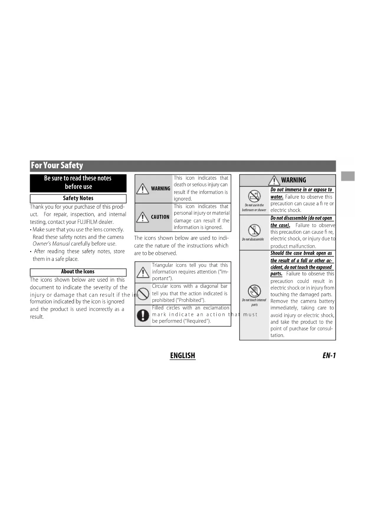
| WARNING | This icon indicates that death or serious injury can result if the information is ignored. |
| CAUTION | This icon indicates that personal injury or material damage can result if the information is ignored. |
The icons shown below are used to indicate the nature of the instructions which are to be observed.
| Triangular icons tell you that this information requires attention ("Important"). | |
| Circular icons with a diagonal bar tell you that the action indicated is prohibited ("Prohibited"). | |
| Filled circles with an exclamation mark indicate an action to be performed ("Required"). |
| WARNING | |
| Do not use in the bathroom or shower | Do not immerse in or expose to water.Failure to observe this precaution can cause a fi re or electric shock. |
| Do not disassemble | Do not disassemble (do not open the case).Failure to observe this precaution can cause fi re, electric shock, or injury due to product malfunction. |
| Do not touch internal parts must | Should the case break open as the result of a fall or other accident, do not touch the exposed parts.Failure to observe this precaution could result in electric shock or in injury from touching the damaged parts.Remove the camera battery immediately, taking care to avoid injury or electric shock, and take the product to the point of purchase for consultation.Do not place on unstable surfaces. The product may fall, causing injury. |
| Do not view the sun through the lens or camera view fi ndFailure to observe this precaution can cause permanent visual impairment. | |
| CAUTION | |
| Do not use or store in locations that are exposed to steam, or smoke or are very humid or extremely dusty. Failure to observe this precaution can cause fi re or electric shock. | |
| Do not leave in direct sunlight or in locations subject to very high temperatures, such as in a closed vehicle on a sunny day.Failure to observe this precaution can cause fi re. | |
WARNING

CAUTION

Do not handle with wet hands. Failure to observe this precaution can cause electric shock.

Keep the sun out of the frame when shooting backlit subjects. Sunlight focused into the camera when the sun is in or close to the frame can cause fire or burns.

When the product is not in use, replace the lens caps and store out of direct sunlight. Sunlight focused by the lens can cause fire or burns.

Do not carry the camera or lens while they are attached to a tripod. The product can fall or strike other objects, causing injury.
For Customers in the U.S.A.
Tested To Comply With FCC Standards FOR HOME OR OFFICE USE
FCC Statement: This device complies with Part 15 of the FCC Rules. Operation is subject to the following two conditions: (1) This device may not cause harmful interference, and (2) this device must accept any interference received, including interference that may cause undesired operation.
CAUTION: This equipment has been tested and found to comply with the limits for a Class B digital device, pursuant to Part 15 of the FCC Rules. These limits are designed to provide reasonable protection against harmful interference in a residential installation. This equipment generates, uses, and can radiate radio frequency energy and, if not installed and used in accordance with the instructions, may cause harmful interference to radio communications. However, there is no guarantee that interference will not occur in a particular installation. If this equipment does cause harmful interference to radio or television reception, which can be determined by turning the equipment off and on, the user is encouraged to try to correct the interference by one or more of the following measures:
- Reorient or relocate the receiving antenna.
- Increase the separation between the equipment and receiver.

- Connect the equipment into an outlet on a circuit different from that to which the receiver is connected.
- Consult the dealer or an experienced radio/TV technician for help.
- You are cautioned that any changes or modifications not expressly approved in this manual could void the user's authority to operate the equipment.
Notes on the Grant: To comply with Part 15 of the FCC Rules, this product must be used with a Fujifi Im-specific ed ferrite-core A/V cable, USB cable, and DC supply cord.
For Customers in Canada
CAN ICES-3 (B)/NMB-3(B)
CAUTION: This Class B digital apparatus complies with Canadian ICES-003.
IMPORTANT SAFETY INSTRUCTIONS
- Read these instructions.
- Keep these instructions.
- Heed all warnings.
- Follow all instructions.
- Do not use this apparatus near water (excluding waterproof products).
- Clean only with a dry cloth.
- Do not block any ventilation openings. Install in accordance with the manufacturer's instructions.
- Do not install near any heat sources such as ra-
diators, heat registers, stoves, or other apparatus (including amplifiers) that produce heat.
- Protect the power cord from being walked on or pinched particularly at plugs, convenience receptacles, and the point where they exit from the apparatus.
- Only use attachments/accessories specified by the manufacturer.
- Unplug this apparatus during lightning storms or when unused for long periods of time.
- Refer all servicing to qualified service personal. Servicing is required when the apparatus has been damaged in any way, such as power supply cord or plug is damaged, liquid has been spilled or objects have fallen into the apparatus, the apparatus has been exposed to rain or moisture, does not operate normally, or has been dropped.
Disposal of Electrical and Electronic Equipment in Private Households
In the European Union, Norway, Iceland and Liechtenstein: This symbol on the product, or in the manual and in the warranty, and/or on its packaging indicates that this product shall not be treated as household waste. Instead it should be taken to an applicable collection point for the recycling of electrical and electronic equipment.

By ensuring this product is disposed of correctly, you will help prevent potential negative consequences to the environment and human health, which could otherwise be caused by inappropriate waste handling of this product.
The recycling of materials will help to conserve natural resources. For more detailed information about recycling this product, please contact your local city office, your household waste disposal service or the shop where you purchased the product.
In Countries Outside the European Union, Norway, Iceland and Liechtenstein: If you wish to discard this product, including the batteries or accumulators, please contact your local authorities and ask for the correct way of disposal.
Australian RCM

ENGLISH
EN-3
Before Using This Product
Some lens features are not available with older versions of the camera fi rmware. Be sure to update the camera fi rmware to the latest version. Instructions on viewing the camera fi rmware version and updating camera fi rmware are available from the following website:
http://www.fujifilm.com/support/digital_cameras/software/#firmware
If you do not have access to a computer, support is available from the local distributor listed in the "FUJIFILM Worldwide Network" material provided with your camera.
Product Care
- When using a lens hood, do not pick up or hold the camera using only the hood.
-
Keep the lens signal contacts clean.
-
Use a blower to remove dust and lint from the glass surfaces of the lens or fi lter. To remove smudges and fi ingerprints, apply a small amount of lens cleaner to a soft, clean cotton cloth or lens-cleaning tissue and clean from the center outwards using a circular motion, taking care not to leave smears or touch the glass with your fi ngers.
- Never use organic solvents such as paint thinner or benzene to clean the lens.
- Attach the front and rear caps when the lens is not in use.
- Store the lens and filter in cool, dry locations to prevent mold and rust. Do not store in direct sunlight or with naphtha or camphc moth balls.
- Keep the lens dry. Rusting can cause irreparable damage. Wipe off rain and water droplets.
• Leaving the lens in extremely hot locations could cause damage or warping.
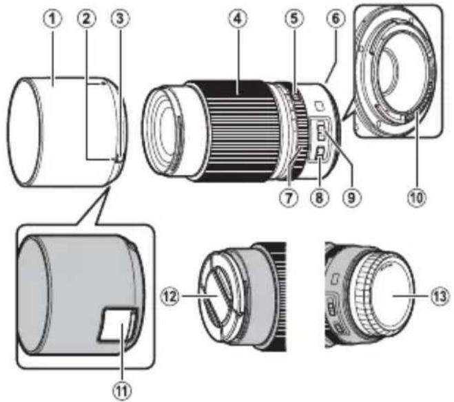
Parts of the Lens
GF120mmF4 R LM OIS WR Macro
text_image
Exploded view diagram of a camera module with numbered parts for identification① Lens hood
② Mounting marks
③ Hood latch release
④ Focus ring
⑤ Aperture ring lock release
⑥ Mounting marks (focal length)
⑦ Aperture ring
⑧ O.I.S. switch
⑨ Focus range selector
⑩ Lens signal contacts
⑪ Filter access port
⑫ Front lens cap
⑬ Rear lens cap
① The lens mount includes a rubber ring to ensure that the lens remains dust- and splash-proof. The ring can be replaced for a fee at any FUJI-FILM service center.
Supplied Accessories
- Front lens cap
- Rear lens cap
- Lens hood
- Lens pouch
Attaching the Lens
See the camera manual for information on attaching and removing lenses.
① This lens is for use exclusively with FUJIFILM G mounts and can not be used with X mounts.
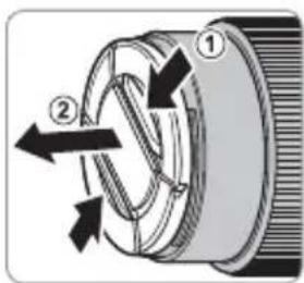
Removing the Caps
Remove the caps as shown.
text_image
Diagram of a mechanical component with numbered parts and directional arrows indicating motion or flow
text_image
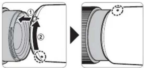
Diagram of a camera lens with labeled parts and directional arrows indicating rotation or movementAttaching the Hood
When attached, lens hoods reduce glare and protect the front lens element.
text_image
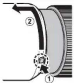
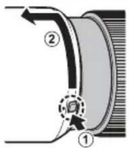
Diagram illustrating mechanical assembly steps with numbered components and directional arrowsRemoving the Hood
To remove the hood, press and hold the hood latch release while rotating the hood counterclockwise.
text_image
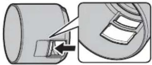
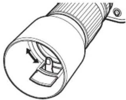
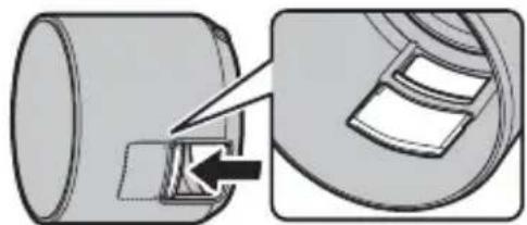
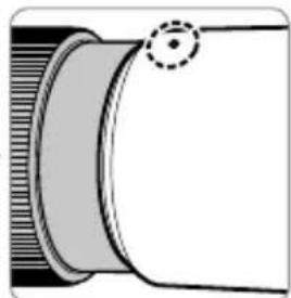
Diagram of a mechanical component with labeled parts ① and ②, showing directional arrows and a dashed circular arrow indicating a specific feature.The Polarizing Filter
To access the polarizing fi Iter, open the fi Iter access port cover.
natural_image
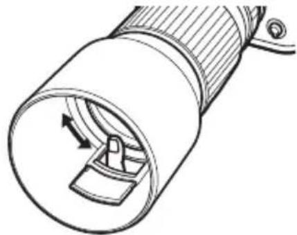
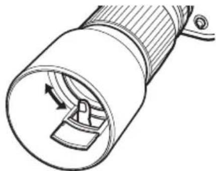
Diagram showing a mechanical component being inserted into a housing, with an arrow indicating the process (no text or symbols present)The filter can be rotated by inserting a finger through the access port.
natural_image
Technical line drawing of a cylindrical device with internal components and directional arrows (no text or symbols)EN-7ENGLI
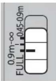
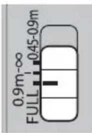
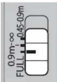
The Focus Range Selector
Choose the focus range for autofocus: FULL (0.45 m–∞) or, for faster focus, 0.9 m–∞ or 0.45–0.9 m.
text_image
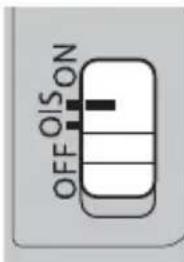
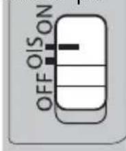
0.9m-∞ FULL 0.45-0.9mOptical Image Stabilization (OIS)
To use optical image stabilization, slide the O.I.S. switch to ON.
text_image
OFF OIS ONEN-8 ENGLISH
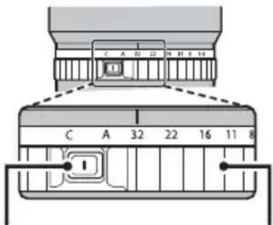
The Aperture Ring
Rotate the lens aperture ring to choose the aperture (f-number).
① C (c): Set aperture to the value chosen with the camera command dial.
② A (A): Set aperture to the value chosen automatically by the camera.
③ Other values (32): Set aperture to the selected value.
To select C or A, or to select another value after selecting C or A, press the aperture ring lock release while rotating the aperture ring.
text_image
C A 32 22 16 11 8Aperture ring lock release
Aperture ring
Specifications
| Type GF120mmF4 R LM OIS WR Macro | |||||
| Lens construction | 14 elements in 9 groups (includes 3 extra low dispersion elements) | ||||
| Focal length (35 mm format equivalent) | f=120 mm (95 mm) | ||||
| Angle of view 25.7° | |||||
| Max. aperture f/4 | |||||
| Min. aperture f/32 | |||||
| Aperture controlNumber of bladesStop size | 9 (rounded diaphragm opening) 13 EV (19 stops) | ||||
| Focus range (measured from focal plane) | 45 cm-infinity | ||||
| Max. magnifi cation 0.5× | |||||
| Reproduction ratio and focus distance | Reproduction ratio 1:21:31:5 | 1:10 | |||
| Focus distance | 0.45 m | 0.57 m | 0.80 m | 1.38 m | |
| External dimensions: Diameter × Length* (approx.)* distance from camera lens mount flange | ∅89.2×152.5 mm | ||||
| Weight* (approx.) * excluding caps and hoods | 980 g | ||||
| Filter size | ∅72 mm | ||||
① Improvements may result in unannounced changes to specifications and appearance.
① Owing to how this lens is constructed, the "Distance indicator" displayed by the camera may in some cases differ from the actual focus distance. Use the "Distance indicator" as a guide only.
This lens uses linear motors to ensure fast and accurate auto focus while maintaining the highest image quality. When the camera is turned off, the lens is disconnected from the camera body, or the playback feature is turned on, there may be an audible sound and slight physical vibration due to the linear motor's magnets being disengaged. This is perfectly normal and will not negatively affect image quality or lens performance.
Pour votre sécurité
http://www.fujifilm.com/support/digital_cameras/software/#firmware
text_image
Exploded view diagram of a camera module with numbered parts for identificationtext_image
Diagram of a mechanical component with numbered parts and directional arrows indicating motion or flow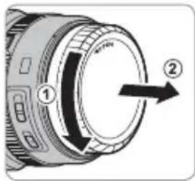
text_image
Diagram of a camera lens with labeled parts and directional arrows indicating rotation or movementtext_image
Diagram illustrating the process of a mechanical component being folded into a cylindrical housing, with numbered parts and directional arrows.text_image
Diagram showing a mechanical or fluid system with labeled components ① and ②, likely illustrating a fluid flow or mechanical process.natural_image
Diagram showing a cylindrical object being cut with an arrow, alongside a magnified view of its internal structure (no text or symbols)natural_image
Technical line drawing of a cylindrical device with internal components and directional arrows (no text or symbols)text_image
0.9m-∞ 0.45-0.9m FULLtext_image
C A 32 22 16 11 8 Ihttp://www.fujifilm.com/support/digital_cameras/software/#firmware
text_image
Exploded view diagram of a camera module with numbered parts for identificationtext_image
Diagram of a mechanical component with numbered parts and directional arrows indicating motion or flow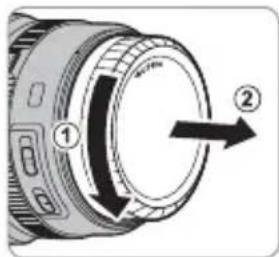
text_image
Diagram of a camera lens with labeled parts and directional arrows indicating rotation or movement.text_image
Diagram illustrating camera lens adjustment process with numbered components and directional arrowsAbnehmen der Haube
text_image
Diagram showing a mechanical component with labeled parts ① and ②, likely illustrating a gear or cam mechanism.Der Polfi Iter
natural_image
Diagram showing a cylindrical object being inserted into a mechanical component, with an arrow indicating the insertion direction (no text or symbols present)natural_image
Technical line drawing of a cylindrical device with internal components and directional arrows (no text or symbols)DE-7DEUTS
text_image
0.9m-∞ FULL 0.45-0.9mhttp://www.fujifilm.com/support/digital_cameras/software/#firmware
text_image
Exploded view diagram of a camera module with numbered parts for identificationtext_image
Diagram of a camera lens with labeled parts and directional arrows indicating rotation or movement.text_image
Diagram illustrating a mechanical assembly process with numbered components and directional arrows indicating motion or movement.text_image
Diagram of a mechanical component with numbered parts and directional arrows indicating motion or flow.natural_image
Diagram showing a mechanical component being inserted into a housing, with no visible text or symbols.natural_image
Technical line drawing of a cylindrical device with internal components and directional arrows (no text or symbols)El selector de rango de enfoque
text_image
0.9m-∞ FULL 0.45-0.9mhttp://www.fujifilm.com/support/digital_cameras/software/#firmware
text_image
Exploded view diagram of a camera module with numbered parts for identification① Zonnekap
② Bevestigingsmarkeringen
③ Kap-ontgrendelingsschuif e
④ Scherpstelring
⑤ Ontgrendeling diafragmaring
⑥ Bevestigingsmarkeringen (brandpuntsafstand)
⑦ Diafragmaring
⑧ O.I.S.-knop
⑨ Scherpstelbereikkeuzeknop
⑩ Lenssignaalcontacten
⑪ Filter toegangspoort
⑫ Voorste lensdop
⑬ Achterste lensdop
text_image
Diagram of a mechanical component with numbered parts and directional arrows indicating motion or flow
text_image
Diagram of a camera lens with labeled parts and directional arrows indicating rotation or movementDe zonnekap bevestigen
text_image
Diagram illustrating a mechanical assembly process with numbered components and directional arrows indicating motion or movement.text_image
Diagram of a mechanical component with labeled parts and directional arrows, showing components ① and ②.natural_image
Diagram showing a mechanical component being inserted into a housing, with an arrow indicating the process (no text or symbols present)natural_image
Technical line drawing of a cylindrical device with internal components and directional arrows (no text or symbols)text_image
0.9m-∞ FULL 0.45-0.9mOptical Image Stabilization (OIS)
http://www.fujifilm.com/support/digital_cameras/software/#firmware
text_image
Exploded view diagram of a camera module with numbered parts for identificationtext_image
Diagram of a mechanical component with numbered parts and directional arrows indicating motion or flow
text_image
Diagram of a camera lens with labeled parts and directional arrows indicating rotation or movement.text_image
Diagram illustrating a mechanical assembly process with numbered components and directional arrows indicating motion or movement.text_image
Technical diagram showing a mechanical component with labeled parts ① and ②, likely illustrating a gear or cam mechanism.Polariseringsfi Itret
natural_image
Diagram showing a mechanical component being inserted into a housing, with an arrow indicating the process (no text or symbols present)natural_image
Technical line drawing of a cylindrical device with internal components and directional arrows (no text or symbols)text_image
0.9m-∞ 0.45-0.9m FULLOptisk bildstabilisator (Optical Image Stabilization - OIS)
http://www.fujifilm.com/support/digital_cameras/software/#firmware
text_image
Exploded view diagram of a camera lens with numbered parts for identification① Solblender
② Monteringsmerker
③ Solblenderutløser
④ Fokusring
⑤ Utløs lås for blenderåpningsring
⑥ Monteringsmerker (brennvidde)
⑦ Blenderring
⑧ O.I.S.-bryter
⑨ Fokusområdevelger
⑩ Objektivets signalkontakter
⑪ Filtertilgangsport
⑫ Fremre objektivdeksel
⑬ Bakre objektivdeksel
text_image
Diagram of a mechanical component with numbered parts and directional arrows indicating motion or force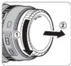
text_image
Diagram of a camera lens with labeled parts and directional arrows indicating rotation or movementtext_image
Diagram illustrating a mechanical assembly process with numbered components and directional arrows indicating motion or movement.Fjerne solblenderen
natural_image
Diagram showing a mechanical component being inserted into a cylindrical housing, with an arrow indicating the process (no text or symbols present)natural_image
Technical line drawing of a cylindrical device with internal components and directional arrows (no text or symbols)NO-7NORSH
Fokusområdevelgeren
Velg fokusområde for autofokus: FULL (0.45 m-∞) eller, for raskere fokus, 0.9 m-∞ eller 0.45 til 0.9 m.
text_image
0.9m-∞ FULL 0.45-0.9mOptisk bildestabilisering (OIS)
http://www.fujifilm.com/support/digital_cameras/software/#firmware
text_image
Exploded view diagram of a camera module with numbered parts for identificationtext_image
Diagram of a mechanical component with numbered parts and directional arrows indicating motion or flow
text_image
Diagram of a camera lens with labeled parts and directional arrows indicating rotation or movement.text_image
Diagram illustrating a mechanical assembly process with numbered components and directional arrows indicating motion or movement.text_image
Technical diagram showing a mechanical component with labeled parts ① and ②, including a dashed circular arrow indicating a specific feature.Polarisaatiosuodin
natural_image
Diagram showing a cylindrical object being inserted into a housing, with an arrow indicating the insertion direction (no text or symbols present)natural_image
Technical line drawing of a cylindrical device with internal components and directional arrows (no text or symbols)FI-7SU0MI
text_image
0.9m-∞ FULL 0.45-0.9mtext_image
C A 32 22 16 11 8 Itext_image
Exploded view diagram of a camera module with numbered parts for identificationtext_image
Diagram of a mechanical component with numbered parts and directional arrows indicating motion or force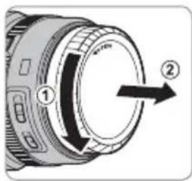
text_image
Diagram of a camera lens with labeled parts and directional arrows indicating rotation or movement.Установка бленды
text_image
Diagram illustrating mechanical assembly steps with numbered components and directional arrowsСнятие бленды
text_image
Technical diagram showing a mechanical component with labeled parts ① and ②, including a circular detail marked with an arrow.natural_image
Diagram showing a mechanical component being inserted into a housing, with no visible text or symbols.natural_image
Technical line drawing of a cylindrical device with internal components and directional arrows (no text or symbols)RU-7PYCCKI
text_image
0.9m-∞ 0.45-0.9m FULLhttp://www.fujifilm.com/support/digital_cameras/software/#firmware
text_image
Exploded view diagram of a camera module with numbered parts for identificationtext_image
Diagram of a mechanical component with numbered parts and directional arrows indicating motion or flow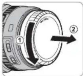
text_image
Diagram of a camera lens with labeled parts and directional arrows indicating rotation or movement.Montaggio paraluce
text_image
Diagram illustrating a mechanical assembly process with numbered components and directional arrows indicating motion or movement.natural_image
Diagram showing a cylindrical object being cut with an arrow, alongside a magnified view of its internal structure (no text or symbols)natural_image
Technical line drawing of a cylindrical device with internal components and directional arrows (no text or symbols)text_image
0.9m-∞ FULL 0.45-0.9mhttp://www.fujifilm.com/support/digital_cameras/software/#firmware
text_image
Exploded view diagram of a camera module with numbered parts for identificationtext_image
Diagram of a mechanical component with numbered parts and directional arrows indicating motion or flow.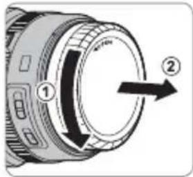
text_image
Diagram of a camera lens with labeled parts and directional arrows indicating rotation or movement.text_image
Diagram illustrating mechanical assembly steps with numbered components and directional arrowstext_image
Technical diagram showing a mechanical component with labeled parts ① and ②, including a dashed circular arrow indicating a feature.Polarisationsfi Iteret
natural_image
Diagram showing a cylindrical object being inserted into a mechanical component, with an arrow indicating the insertion direction (no text or symbols present)natural_image
Technical line drawing of a cylindrical device with internal components and directional arrows (no text or symbols)DA-7DANSH
Fokusområdevælgeren
Vælg fokusområde for autofokus: FULL (0,45 m–∞) eller, for hurtigere fokus, 0.9 m–∞ eller 0.45–0.9 m.
text_image
0.9m-∞ FULL 0.45-0.9mOptisk billedstabilisering (OIS)
For at anvende optisk billedstabilisering skal du skubbe O.I.S.-kontakten over på ON.
text_image
OFF OIS ONDA-8 DANSK
Blænderingen
http://www.fujifilm.com/support/digital_cameras/software/#firmware
text_image
Exploded view diagram of a camera module with numbered parts for identificationtext_image
Diagram of a mechanical component with numbered parts and directional arrows indicating motion or flow
text_image
Diagram of a camera lens with labeled parts and directional arrows indicating rotation or movement.text_image
Diagram illustrating a mechanical assembly process with numbered components and directional arrows indicating motion or movement.Zdejmowanie osłony
text_image
Technical diagram showing a mechanical component with labeled parts ① and ②, including a dashed circular arrow indicating a specific feature.Filtr polaryzacyjny
natural_image
Diagram showing a cylindrical object being cut with an arrow, alongside a magnified view of a mechanical component (no text or symbols)natural_image
Technical line drawing of a cylindrical device with internal components and directional arrows (no text or symbols)PL-7POLSK
text_image
0.9m-∞ FULL 0.45-0.9mhttp://www.fujifilm.com/support/digital_cameras/software/#firmware
text_image
Exploded view diagram of a camera module with numbered parts for identificationtext_image
Diagram showing two views of a camera lens with numbered parts and directional arrows indicating rotation or adjustment.安装遮光罩
text_image
Diagram illustrating mechanical assembly steps with numbered components and directional arrows取下遮光罩
text_image
Diagram showing a mechanical or fluid system with labeled components ① and ②, including directional arrows and a dashed arrow indicating flow or movement.偏光滤镜
natural_image
Diagram showing a mechanical component being inserted into a housing, with an arrow indicating the insertion direction (no text or symbols present)随后,将手指插入操作端口即可旋转滤镜。
natural_image
Technical line drawing of a cylindrical device with internal components and directional arrows (no text or symbols)中文简
ZHS-7
对焦范围选择器
text_image
0.9m-∞ FULL 0.45-0.9m光学图像稳定(OIS)
http://www.fujifilm.com/support/digital_cameras/software/#firmware
text_image
Exploded view diagram of a camera module with numbered parts for identificationtext_image
Diagram showing two views of a camera lens with numbered parts and directional arrows indicating rotation or adjustment.安裝遮光罩
text_image
Diagram illustrating mechanical assembly steps with numbered components and directional arrows取下遮光罩
若要取下遮光罩,請按住遮光罩釋放栓扣並同時逆時針旋轉遮光罩。
text_image
Technical diagram showing a mechanical component with labeled parts ① and ②, likely illustrating a gear or cam mechanism.偏光濾鏡
若要操作偏光濾鏡,請打開濾鏡操作埠蓋。
natural_image
Diagram showing a cylindrical object being cut with an arrow, alongside a magnified view of its internal structure (no text or symbols)隨後,將手指插入操作埠中即可旋轉濾鏡。
natural_image
Technical line drawing of a cylindrical device with internal components and directional arrows (no text or symbols)對焦範圍選擇器
text_image
0.9m-∞ FULL 0.45-0.9m光學影像穩定(OIS)
http://www.fujifilm.com/support/digital_cameras/software/#firmware
text_image
Exploded view diagram of a camera module with numbered parts for identificationtext_image
Diagram of a mechanical component with numbered parts and directional arrows indicating motion or flow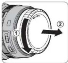
text_image
Diagram of a camera lens with labeled parts and directional arrow indicating rotation or movement후드부착
text_image
Diagram illustrating a mechanical assembly process with numbered components and directional arrows indicating motion or movement.후드 제거
text_image
Technical diagram showing a mechanical component with labeled parts ① and ②, including a dashed circular arrow indicating a specific feature.편광 필터
natural_image
Diagram showing a cylindrical object being cut with an arrow, alongside a magnified view of its internal structure (no text or symbols)natural_image
Technical line drawing of a cylindrical device with internal components and directional arrows (no text or symbols)초점 범위 셀렉터
text_image
0.9m-∞ FULL 0.45-0.9m광학 이미지 보정(OIS)
text_image
0.9m-∞ FULL 0.45-0.9m.0.9-0.45 - ∞-0.45 .0.9 - ∞-0.45 (كلمل) (0.45) ∞-0.45 .0.9 - ∞-0.45 (كلمل) (0.45) ∞-0.45 .0.9 - ∞-0.45
natural_image
Diagram showing a cylindrical object being inserted into a slot, with an arrow indicating the insertion direction (no text or symbols present)natural_image
Technical line drawing of a cylindrical device with internal components and directional arrows (no text or symbols)تركيب stickواقية
text_image
Technical diagram showing mechanical assembly with numbered components and directional arrows indicating motion or movement.
natural_image
Pure diagram of a cylindrical object with a circular mark on its side, no text or symbols presentزالكة الواقية
text_image
Diagram of a mechanical component with numbered parts, likely illustrating a turning or positioning process.عربي
AR-7
زالالة蓝图اء
text_image
Diagram of a mechanical component with numbered parts and directional arrows indicating motion or flow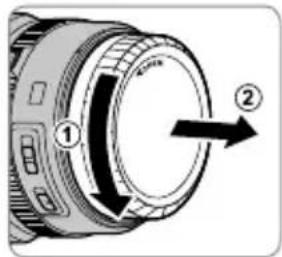
text_image
Diagram of a camera lens with labeled parts and directional arrows indicating rotation or movementالإكسوارات المرفقة
• الأمامي
• الخلفي
• العدسة
• العدسة
تركيب الاددسة