
Mecablitz 64 AF1 digital - Flash METZ - Free user manual and instructions
Find the device manual for free Mecablitz 64 AF1 digital METZ in PDF.
| Product type | Dedicated cobra flash for FourThirds/Micro FourThirds digital cameras (Olympus, Panasonic, Leica) |
| Dimensions (H x W x D) | Approx. 78 × 148 × 112 mm |
| Weight | Approx. 422 g (without batteries) |
| Power supply | 4 AA batteries/rechargeable batteries (LR6/HR6): alkaline, NiMH, lithium; or optional Powerpack |
| Maximum guide number (ISO 100, 200 mm) | 64 (m) / 210 (ft) |
| Flash modes | TTL, TTL FP, Manual (M), M FP, Automatic (A), Stroboscope, Remote Slave, Servo |
| Manual power range | 1/1 to 1/256 (M mode); 1/1 to 1/64 (M FP mode) |
| Flash duration (1/1) | Approx. 1/200 s (according to manual table 2) |
| Color temperature | Approx. 5600 K |
| Supported ISO sensitivity | ISO 6 to 51200 |
| Synchronization | 1st curtain, 2nd curtain (REAR), slow speed (SLOW), high speed (FP) automatic |
| Number of flashes (alkaline batteries) | Approx. 140 |
| Recycling time (min./max.) | 0.1 s / 4.4 s (alkaline); 0.1 s / 1.8 s (NiMH) |
| Zoom head orientation | Vertical: -9° (macro) to 90°; Horizontal: 180° (left) / 120° (right) with click stops |
| Motorized zoom | Yes, from 12 mm (with wide-angle diffuser) to 200 mm (automatic or manual) |
| Touchscreen | Yes, with brightness adjustment and automatic rotation |
| Wireless flash | Remote mode (master/slave) up to 3 groups (A, B, C) and 4 channels; Servo mode |
| AF assist light | Yes, built-in, enable/disable (range approx. 6-9 m) |
| Special functions | RAPID mode, secondary reflector, pilot light, exposure bracketing, favorite program (4 memories), key lock |
| Maintenance and cleaning | Soft dry cloth; do not spray liquid; form the capacitor every 3 months if unused |
| Safety | Do not fire near eyes, flammable gases; do not disassemble (high voltage); allow rest after 20 full-power flashes |
| Spare parts and repairability | Optional accessories available (diffusers, softbox, stand, cables, powerpack); firmware update via USB; factory reset possible |
| General information | 302-page manual available in multiple languages; compatible with Olympus/Panasonic/Leica TTL systems |
Frequently Asked Questions - Mecablitz 64 AF1 digital METZ
User questions about Mecablitz 64 AF1 digital METZ
0 question about this device. Answer the ones you know or ask your own.
Ask a new question about this device
Download the instructions for your Flash in PDF format for free! Find your manual Mecablitz 64 AF1 digital - METZ and take your electronic device back in hand. On this page are published all the documents necessary for the use of your device. Mecablitz 64 AF1 digital by METZ.
USER MANUAL Mecablitz 64 AF1 digital METZ
mecablitz 64 AF-1 digital
15.2 Rotation (ROTATION)
Easy Softbox ESB 40-40
(Bestellnr.009014047)
Abmessungen: 40 × 40 cm
15.2 Rotation (ROTATION)
Easy Softbox ESB 40-40
(ref. 009014047)
Dimensions: 40 × 40 cm
- Mini Octagon Softbox SB 15-15
(ref. 009021516)
Coloris: blanc, dimensions: 0 15 cm
Ecran reflex Spot SD 30-26 W
(ref. 009043021)
De flitser is gereed.
Afmetingen ong. in mm (B x H x D):
Ca. 78 × 148 × 112
Gewicht :
Easy Softbox ESB 40-40
(Bestelnr.009014047)
Afmetingen: 40 × 40 ~cm
Thank you for choosing a Metz mecatech product. We are delighted to welcome you as a customer.
You will of course be impatient to start using the flash unit. However, it is worthwhile reading the operating instructions and learning how to use the unit correctly.
This flash unit is suited for:
- Olympus - Digital cameras with Micro FourThirds/FourThirds TTL flash control and flash socket system, as well as the compatible digital cameras from Panasonic and Leica.
This flash unit is not suited for other brands of cameras.
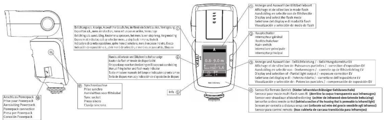
Take a look at the diagrams at the end of the manual.
Declaration

Tip, note

Attention -Extremely important safety information!
Proper Use
This flash unit is intended solely for taking pictures of motifs in the photographic field. It may be operated only with the accessories described in this instruction manual or the accessories approved by Metz.
The flash unit may not be used for any purpose other than that described above.

1 Safety instructions
The flash unit may in no event be activated in the vicinity of inflammable gases or liquids (petroleum, solvents etc.). RISK OF EXPLOSIONS!
Do not flash directly into eyes from a close distance! Direct flashing into the eyes of persons or animals can cause damage to the retina and severe disruption of the vision - up to and including permanent blindness!
Never use a flash unit to photograph car, bus, bicycle, motorbike or train drivers while they are driving. Blinding the driver can lead to an accident!
If the housing has been damaged in such a way that internal components are exposed, the flash unit may no longer be used. Remove the batteries! Do not touch any internal components. HIGH VOLTAGE!
After repeated flashing, do not touch the diffuser. Risk of burns!
Do not dismantle the flash unit! HIGH VOLTAGE! Repairs should only be performed by authorised service personnel.
The flash unit is exclusively designed and authorised for use in photographic applications.
- Only use the power sources designated and autho-rised in the operating manual!
- Do not open the batteries or short them!
- In no event the batteries be exposed to high temperatures like direct sunlight, fire or similar!
- Never throw flat/dead batteries onto a fire!
- Do not use any toxic batteries or rechargeable batteries!
- Remove the used batteries immediately from the device! Chemicals can escape from used batteries (so-called "leaks") resulting in damage to the device!
- Batteries may not be recharged!
- Do not expose the flash unit to water drops and splashes!
- Protect your flash unit from heat and high air humidity! Do not keep it in the glove compartment of your car!
- Rapid changes in temperature may lead to condensation. If this occurs, allow time for the unit to become acclimatized!
- When you activate the flash, there should be no opaque material directly in front of or on the reflector cover (flash window). The intense energy emissions can otherwise lead to scorching or spotting of the material and/or the reflector cover.
After a series of flashes with full power and short intervals, a pause of at least 3 minutes must be observed after each series of 20 flashes!! - When taking a series of flash shots at full light output and with rapid recycling times, and with zoom positions of 35mm and less, the diffuser heats up, due to the high level of thermal energy.
- This flash unit may be used in combination with a camera-integrated flash only if the flash can be folded out completely.
2 Dedicated flash functions
Dedicated flash functions are flash functions that have been specially adapted to a given camera system. Depending on the type of camera, different flash functions are supported.
- Flash-ready indication in camera viewfinder/camera display.
Automatic flash sync speed control.
Automatic flash sync speed control. - TTL flash mode.
- Manual flash exposure correction for TTL.
- FourThirds/Micro-FourThirds-System compatible
- 1st or 2nd curtain-synchronisation (SLOW2). (Camera setting)
Automatic FP short sync forTTL and M.
Automatic motor zoom control. - Extended zoom mode.
- AF measuring beam control.
Automatic flash range indication. - Programmed auto flash mode.
- Preflash for red-eye reduction
- Wireless TTL remote flash mode.
- Servo mode.
- Spot zoom mode.
- Wake-up function for the flash unit.

It is impossible to describe all camera types and their individual dedicated flash functions within the scope of these instructions. Therefore, please refer to the flash mode description in your camera's operating instructions to find out which functions are supported and which ones have to be set manually on the camera.
Using lenses not equipped with a CPU (i.e., lenses without auto focus mode), results in certain functional limitations!

3 Preparing the flash unit for use
3.1 Mounting the flash unit
Mounting the flash unit on the camera

Turn off the camera and flash before mounting or removing.
- Turn the knurled nut ⑬ towards the flash unit housing as far as it will go. The locking pin in the adapter shoe is now fully retracted into the case.
- Slide the flash unit foot completely into the camera accessory shoe.
- Turn the knurled nut 13 towards the camera housing as far as it will go, clamping the flash unit in place. If the camera does not have a locking hole, the spring-loaded loking pin retracts into the adapter case so as not to damage the surface.
Removing the flash unit from the camera

Turn off the camera and flash before mounting or dismounting.
- Turn the knurled nut ⑬ towards the flash unit housing as far as it will go.
- Remove the flash unit from the camera's accessory shoe.
3.2 Power supply
Suitable batteries/rechargeable batteries
The flash unit can be operated with any of the following batteries:
- 4 nickel-metal-hydride batteries 1.2V , type IEC HR6 (size AA). They have a significantly higher capacity than NiCad batteries and are less harmful to the environment, since they have no cadmium.
- 4 alkaline-manganese dry cell batteries 1.5V, type IEC LR6 (size AA). Maintenance-free power source for moderate power requirements.
- 4 lithium batteries 1.5V, type IEC FR6 (size AA). Maintenance-free high-capacity power source with a low self-discharge rate.
- Power Pack con cavo di collegamento (accessorio speciale).
Please only use the power sources given above. If other power sources are used, there is a risk of damaging the flash unit.
If your flash unit is not going to be used for an extended period of time, remove the batteries.

Replacing batteries
The disposable/rechargeable batteries are empty or used up if the recycling time (time from the triggering of a full-power flash, e.g. in the M mode, to the moment the flash-ready indicator lights up again) exceeds 60 seconds. In addition, the battery warning appears on the touch display.
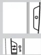
- Switch off the flash unit. To do this, press the ① ② button until all displays turn off.
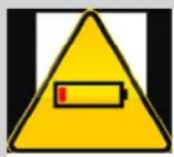
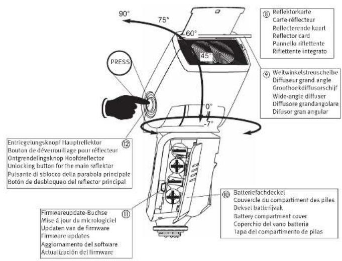
- Slide the battery compartment cover ⑩ downwards and fold open.
- Insert the batteries lengthwise as indicated by the battery symbols provided and close the battery compartment cover 10.
When inserting batteries, ensure that the polarity is correct and matches the symbols in the battery compartment. Inserting the batteries in the wrong direction can destroy the flash unit! Always replace all batteries simultaneously, and make sure that batteries are the same brand and have the same capacity. Flat or dead batteries should not be disposed of with ordinary household waste. Help protect the environment, and dispose of flat/dead batteries at the appropriate collection points.

OPTION
OPTION

RAPID
SUB-REFL.
ZOOM SIZE
ZOOM MODE
STANDBY
MOD.LIGHT
BEEP
m/ft
POWERPACK
AF BEAM
FLASH BRACK.
REAR
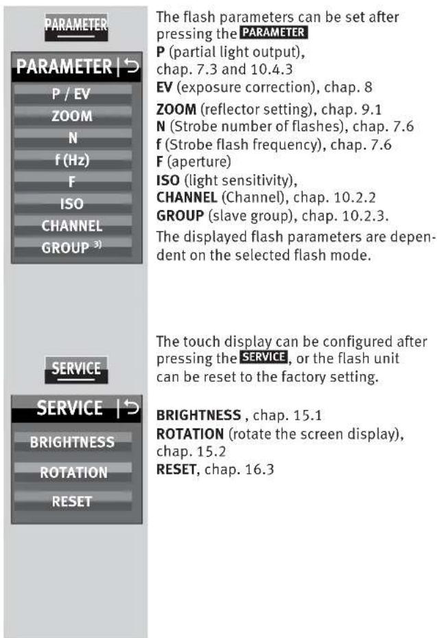
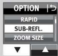
The options can be set after pressing the OPTION button.
RAPID (fast recycling times), chap. 11.1
SUB-REFL (secondary reflector), chap. 11.2
ZOOM SIZE (shooting format adjustment), chap. 11.5
ZOOM MODE (illumination), chap. 11.4
STANDBY (autom., unit switch-off), chap. 3.6
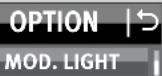
MOD.LIGHT (modelling light), chap. 11.3
BEEP (acoustic signal), chap. 11.9
m / ft (metres / feet), chap. 11.7
POWERPACK (external power pack), chap. 11.11
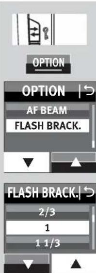
AF BEAM (AF auxiliary light), chap. 11.6
FLASH BRACK. (flash bracketing series), chap. 11.8
The displayed flash parameters are dependent on the selected flash mode. In the menus shown on the flash unit, all fields that have a black background are configured as sensor buttons that can be pressed for modifications/changes in the menu.
In the images in the user's guide, only the sensor buttons that must be pressed for setting the described function are marked in black.


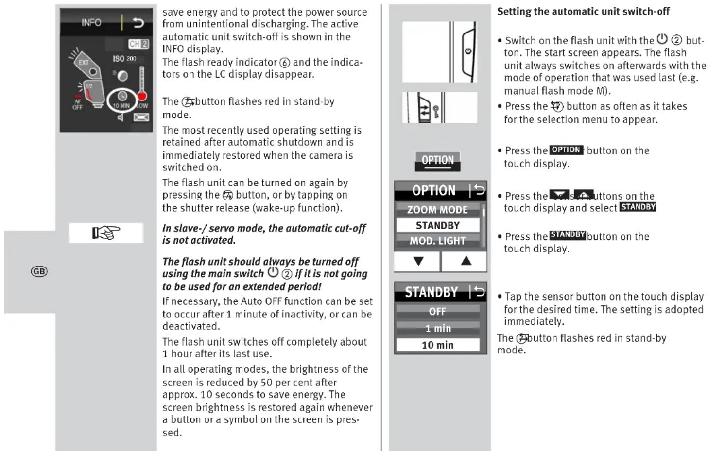
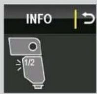
3.5 INFO
The current settings of the flash unit can be displayed during operation.
Press the ① tensor button on the touch display. Info appears.
-EXT (extended zoom mode) is set, (chap. 11.4.1).
- AF OFF (AF auxiliary light) is switched off, (chap. 11.6).
- W.D.LIGHT) is set, (chap. 11.3).
- (beep function) is set, (chap. 11.9)
- (Chattel) appears on the display, chap. 10.1.2, 10.2.2)
- The automatic unit switch-off is set for 10 minutes (chap. 3.6).
- The temperature display increases after intensive use.
3.6 Auto OFF for the flash unit
The flash unit is factory-set to automatically switch to standby mode (Auto OFF) 10 minutes after
- being switched on,
- a flash is fired,
the shutter release is actuated,
the camera's exposure metering system is switched off. ..
... switched to stand-by mode, (Auto-OFF) to

4 LED displays on the flash unit
4.1 Flash readiness indication
When the flash capacitor on the flash unit is charged, the ⑥ button lights up in green, thus indicating that the flash unit is ready. This means that flash light can be used for the next shot. Flash readiness is also transmitted to the camera and indicated accordingly in the camera's viewfinder.
If a photograph is taken before flash readiness appears, then the flash unit will not be triggered. If the camera has already switched to flash sync speed, the shot may have the wrong exposure (see 14.1).
4.2 Correct exposure indication
If the exposure is correct, then button ⑦ lights up in red for around 3 seconds if the photograph has been correctly exposed in flash modes TTL TL FP (); TTFFP
see 7.1) as well as automatic mode A If there is no exposure control indication after the shot, then the photograph was underexposed.
In that case, you must:
- set the next smaller f-stop (e.g. use f-stop 8 instead of 11), or
- reduce the distance to the subject or to the reflection surface (e.g. for indirect flashes), or
- set a higher ISO value on the camera.
Note the maximum flash range indicated on the display of the flash unit (see 5.2).
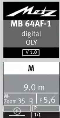
5 Information in Display
The cameras transmit the settings for ISO, lens focal length (mm) and aperture to the flash unit.
It calculates the maximum flash range from the settings and their guide number.
Flash mode, range and zoom position of the reflector are displayed in the display of the flash unit.
If the flash unit is operated without receiving data from the camera, then the values set on the flash unit will be shown.
Display illumination
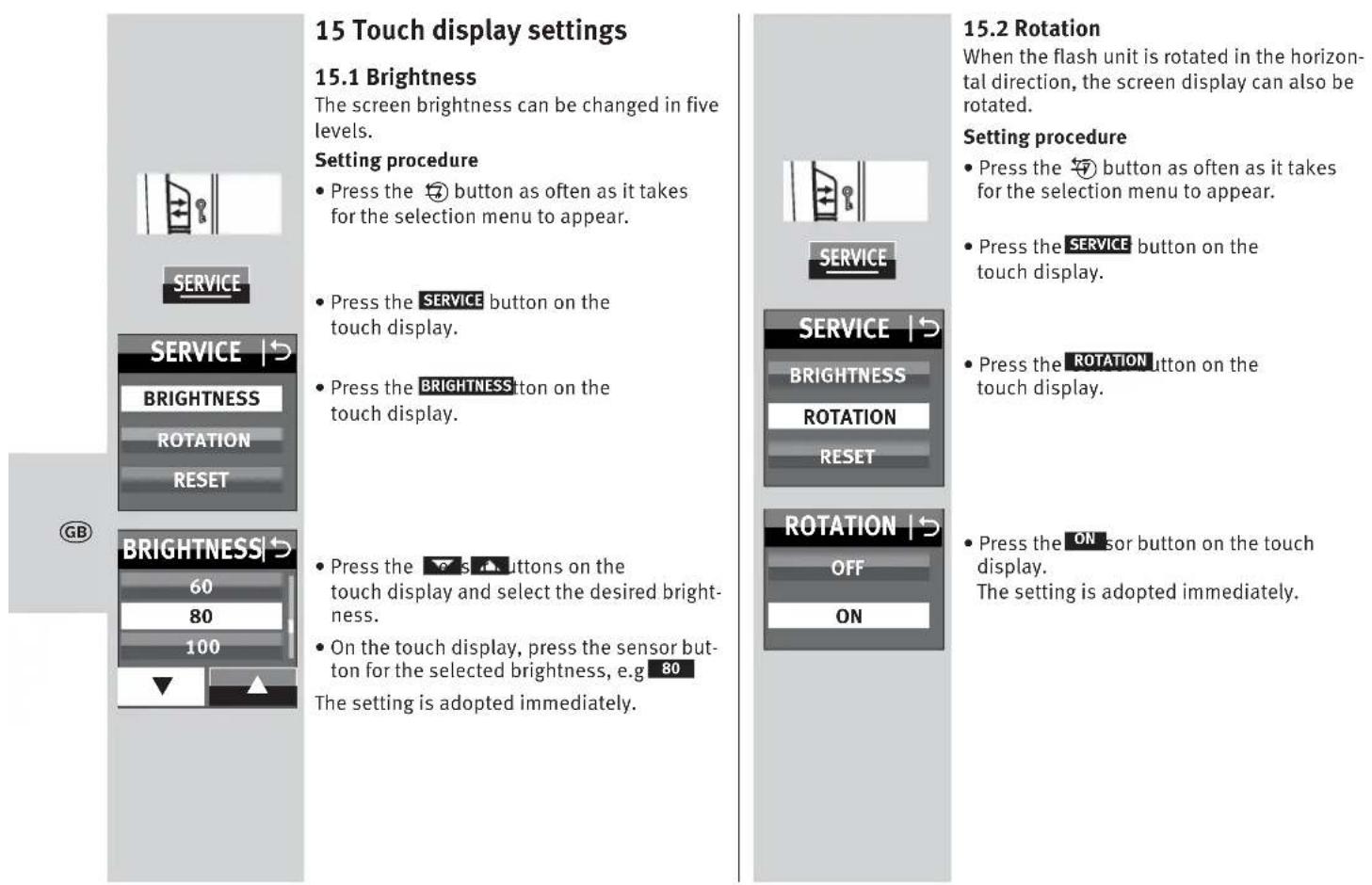
After pressing the ⑦ button on the flash unit, or after tapping the touch display, the display illumination will be at maximum level for approximately 10 sec.
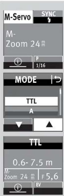
5.1 Display of the flash mode
The current flash mode is shown in the display. Depending on the type of camera, different displays are available for the selected TTL flash mode (e.g. ) an TLP the manual flash mode M (see 7.3).
5.2 Range display
When using cameras and a lens with CPU, the range is indicated in the display. For this a data exchange must have occurred between the camera and flash unit, for example by tapping the shutter release. The range can be displayed either in metres (m) or feet (ft) - see 11.7.
The flash range is not displayed when . . .
- no data is transmitted from the camera.
- when the reflector head is tilted out of its normal position (upwards or sideways).
- if the flash unit is working in REMOTE MASTER, REMOTE SLAVE or SERVO mode.
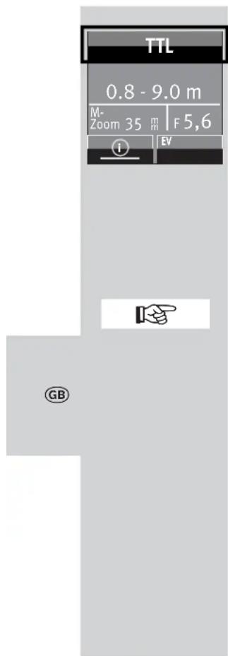
Range display in TTL-
TTL FP- flash modes
In the TTL flash modes; sTTLFP the value for the minimum and the maximum range of the flash unit is displayed.
The value indicated relates to subjects with a reflection factor of 25% , which applies to most photographic situations.
Strong deviations from this reflection factor, as in the case of highly reflective or poorly reflective subjects, may affect the flash range of the flash unit.
The subject should be in the range of 40% to 70% of the maximum range. This will give the electronics sufficient scope for compensation.
To prevent overexposure, the minimum distance to the subject shown in the display should not be undershot.
Adjustment to the photographic situation at hand can be achieved by, for example, changing the aperture of the setting on the lens.
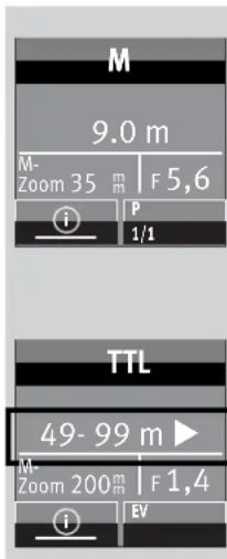
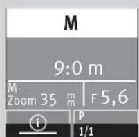
Range display in manual flash mode M
In manual flash mode, the distance that must be maintained from the subject for correct flash exposure is indicated. Adjustment to the photographic situation at hand can be achieved by, for example, changing the aperture setting on the lens or selecting a manual partial light output level (see 7.3).
Exceeding the display range
Flash ranges of up to 99 m or 99 ft can be shown in the display.
This display range can be exceeded in the case of high ISO values and large aperture openings.
An arrow or triangle after the distance value indicates that the display range has been exceeded.
6 Displays in the camera viewfinder
Examples for the camera viewfinder display:
Flash symbol flashes
Command to switch on or use the flash unit.
Flash symbol is illuminated
The flash unit is ready for firing.
For information applicable to the displays in the viewfinder of your camera model, refer to the camera's operating instructions.
Incorrect exposure guidelines:
- overexposure: do not use the flash!
underexposure: switch the flash on or use a tripod and a longer exposure time.
Reasons for incorrect exposure can lay in the various exposure and automatic programmes.
For information applicable to the displays in the viewfinder of your camera model, refer to the camera's operating instructions.
7 Flash modes
Depending on the camera model, the following flash modes are available:
- TTL flash mode (Hap. 7.1
Automatic high-speed synchronisation (FP), chap. 7.4
Automatic flash mode (A hap. 7.5 - Manual flash mode (M hap. 7.3)
Strobe flash mode (STROBO).7.6 - REMOTE MASTER flash mode (adjustable only on camera)
- REMOTE SLAVE:ap.10.2
SERVO mode, chap. 10.4
The flash mode is set using the touch display.
A data transfer between flash unit and camera is necessary before setting flash modes
and MFP by actuating the shutter release.
7.1 TTL flash mode (TL)
These flash modes offer a very simple method of obtaining very good flash shots. Here, the exposure is measured by a sensor in the camera. It measures the light reflected by the subject through the lens (TTL = "Through The Lens").
If the shot was exposed correctly, the correct exposure indication will illuminate for about 3 seconds (see 4.2).
When taking a shot, an almost imperceptible measurement pre-flash is triggered by the camera prior to the actual exposure process.
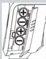
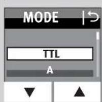
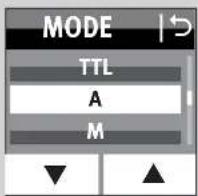
Setting the mode of operation
- Switch on the flash unit with the button.
The start screen appears. Thereafter, the flash unit always switches on with the mode of operation that was used last (e.g. M flash mode). - Press the displayed mode of operation on the touch display as many times as it takes for the display for selecting the mode of operation to appear.
- Press the buttons on the touch display and select TLI
- Press on the selected mode of operation that is highlighted in yellow. The setting is adopted immediately.
- Set a suitable mode of operation on the camera, e.g. P, S, A etc.
- Tap the shutter release to transfer data between the flash unit and the camera.
7.2 Automatic TTL Fill-in flash mode
The automatic TTL fill-in flash mode is activated by most cameras when the automatic programme P is selected and by Vari or subject programmes during daylight (see camera operating manual).
Fill-in flash mode overcomes troublesome shadows and produces a more balanced exposure between subject and background with centre-jour shots. The camera's computer-controlled metering system sets the most suitable combination of shutter speed, aperture and flash output.
Ensure that the contre-jour light source does not shine directly into the lens, as this will interfere with the camera's TTL metering system!
There is no setting or display for automatic TTL fill-in flash in the flash unit.
7.3 Manual flash mode
In the manual flash mode M, the flash unit emits the full uncontrolled amount of light if no partial light output has been selected. The specific photographic situation can be taken into account by adjusting the aperture setting or by selecting a suitable manual partial light setting.
The setting area ranges from P 1/1 to P1/256
in 1e and P1/1 - 1/64 in M FPM
mode.
The display shows the distance at which the subject is correctly lit (see 5.2).
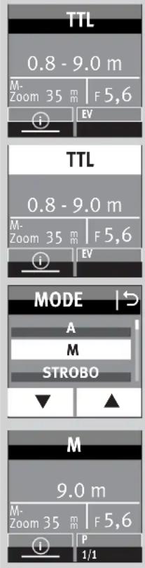
Setting the mode of operation
- Switch on the flash unit with the ② button.
The start screen appears. Thereafter, the flash unit always switches on with the mode of operation that was used last. - Press the sensor button of the displayed mode of operation on the touch display as many times as it takes for the display for selecting the mode of operation to appear.
- Press the 串 buttons on the touch display and select M
- Press the Mnsor button on the touch display.
- Set a suitable mode of operation on the camera, e.g. M
- Tap the shutter release to transfer data between the flash unit and the camera.
Various cameras support manual flash mode M only in the camera's M mode (manual). In other camera models, an error message appears in the display and the release is locked.
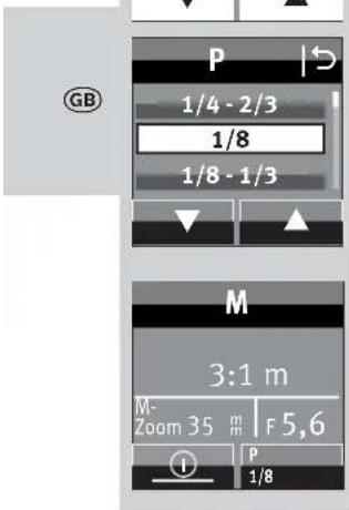
Manual partial light output levels
Partial light output can be set in manual flash mode M.
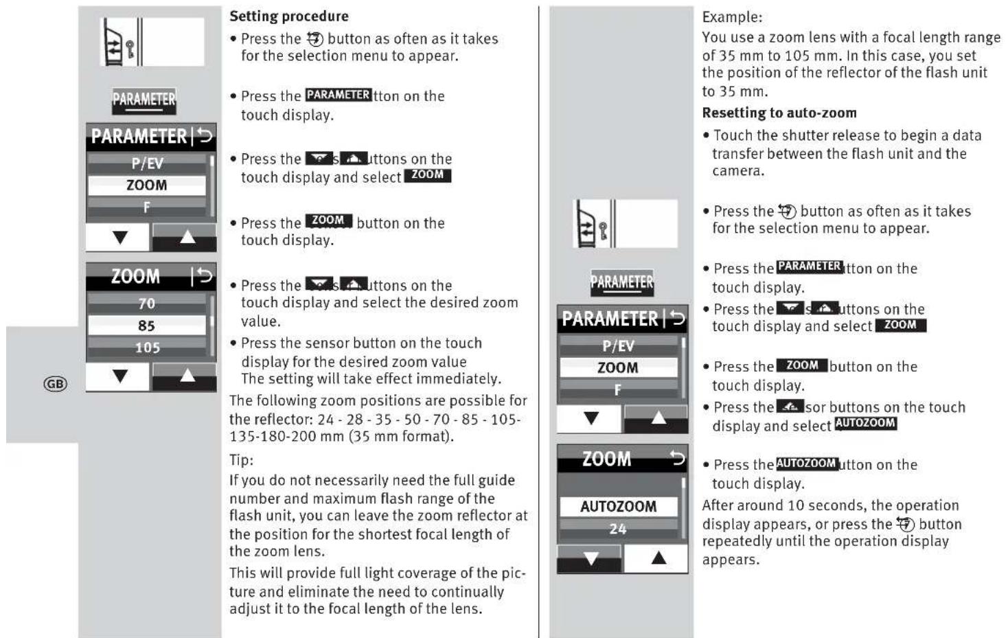
Setting procedure
- Press the sensor button for partial light output on the touch display as many times as it takes for the partial light output display to appear.
Press sensor buttons
touch display and set the desired partial light output to 1/1, 1/2, 1/8 ... 1/256.
- Press the sensor button on the touch display for the selected partial light output.
The setting is immediately effective and automatically saved.
The distance display is adjusted to the partial light output automatically (see 5.2).
7.4 Automatic high-speed synchronisation (FP)
Various cameras support automatic high-speed synchronisation (see the camera's operating instructions). This flash mode makes it possible to use a flash unit even with shutter speeds that are faster than the flash sync speed.
Interesting results may by achieved in this mode when, for example, a wide open aperture (e.g., f/2.0) is used to limit the depth of field in portrait shots taken in very bright ambient light. The flash unit supports high-speed synchronisation in TIL flas modes.
For physical reasons, however, high-speed synchronisation significantly reduces the number and the maximum flash range.
Be sure to note, therefore, the flash range on the display of the flash unit. High-speed synchronisation is activated automatically if a shutter speed faster than the flash sync speed is set on the camera, whether manually or automatically by the exposure program. Note that in the case of high speed synchronisation the guide number of the flash unit also depends on the shutter speed.
The faster the shutter speed, the lower the guide number!
The setting for automatic high-speed synchronisation occurs on the camera (see camera operating instructions)!
The display of the flash unit then in addition shows "FP" (TLFP)
7.5 Automatic flash mode
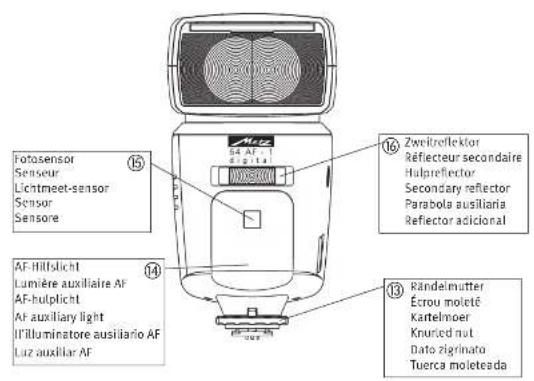
In the automatic flash mode A he flash unit sensor 5 measures the light that reflects back from the subject. The sensor 15 has a coverage of about 25^ and only measures the light for the time a flash is fired by the mecablitz.
The flash is cut off as soon as sufficient light has been emitted for correct exposure. The sensor 15 of the mecablitz has to be directed at the subject.
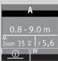
Setting the mode of operation
- Switch on the flash unit with the ② button.
The start screen appears. Thereafter, the flash unit always switches on with the mode of operation that was used last. - Press the sensor button of the displayed mode of operation on the touch display as many times as it takes for the display for selecting the mode of operation to appear.
- Press the l & buttons on the touch display and select A
- Press the Ansor button on the touch display.

- Set a suitable mode of operation on the camera, e.g. A
- Tap the shutter release to transfer data between the flash unit and the camera.
7.6 Strobe flash mode
The strobe flash mode is a manual flash mode. It allows several flash exposures to be made on a single photo, which can be especially interesting for movement studies or special effect images. In strobe flash mode, several flashes at a certain flash frequency are emitted. For this reason, this function is only possible with a partial light output of 1/8 or less.
For a strobe exposure, the frequency of the flashes (flashes per second) as well as the number of flashes must be selected.
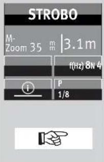
Strobe number of flashes (N)
In strobe mode, the number of flashes per shot (N) can be selected.
The number of flashes can be set from 2 to 90, depending on the set partial light output.
The maximum possible number of flashes (N) depends on the set partial light output (P) .
Strobe flash frequency (f)
Strobe mode allows you to select the flash frequency (f), which indicates the number of flashes per second.
The number of flashes can be set from 1 to 100. The maximum possible number of flashes is automatically adjusted.
If you desire short flashes, you can manually reduce the partial light output to the lowest value of 1/256.

The maximum possible frequency of flashes (f) depends on the set partial light output (P) .
Setting the mode of operation
- Switch on the flash unit with the ① ② button.
The start screen appears. Thereafter, the flash unit always switches on with the mode of operation that was used last.
$$ 0. 8 - 9. 0 \mathrm {m} $$
$$ \begin{array}{l} \text {M -} \ \text {Z o o m 3 5 m} \end{array} \mid F 5, 6 $$

TTL
- Press the sensor button of the displayed mode of operation on the touch display as many times as it takes for the display for selecting the mode of operation to appear.


STROBO
REMOTE SLAVE


$$ Z n o m 3 5 \quad m \quad 3. 1 m $$
$$ f (h z) 5 N 5 $$

1/8
- Set a suitable mode of operation on the camera, e.g. M
- Tap the shutter release to transfer data between the flash unit and the camera.

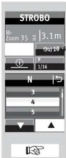
Set number of flashes (N)
- Press the sensor button for the number of flashes N touch display.
- Press the s. buttons on the touch display and select the desired number of flashes.
The maximum possible number of flashes (N) depends on the set partial light output (P) .
Press the sensor button on the touch display for the desired number of flashes (in the example 4 The setting will take effect immediately.
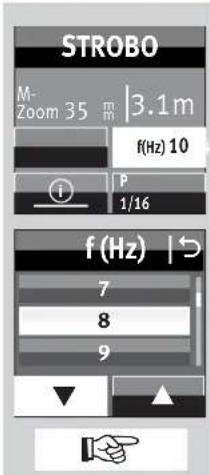
Setting the flash frequency (f(Hz))
Press the sensor button on the touch display for the flash frequency fHz
- Press the buttons on the touch display and select the desired frequency of flashes.
The maximum possible frequency of flashes (f) depends on the set partial light output (P) .
- Press the sensor button on the touch display for the desired frequency of flashes in the example 8 The setting will take effect immediately.
The valid distance to the set parameters is shown on the display.
The distance value displayed can be adjusted to the distance from the subject by changing the f-stop or the partial light output. The aperture and ISO values are not shown on the display in Strobe flash mode!
The secondary reflector is not supported in stroboscopic flash mode.
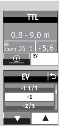
8 Manual flash exposure correction
The auto flash exposure mode of most cameras is adjusted to a reflection factor of 25% (the average reflection factor of flash subjects).
A dark background that absorbs much of the light or a highly reflective bright background (backlit shots, for example) may result in, respectively, underexposure or overexposure of the subject.
To offset these effects, the flash exposure can be adjusted manually for the shot with a correction value. The extent of the correction depends on the contrast between the subject and background!
In A/TTL flash modes, manual flash exposure correction factors of from -3 EV (f-stops) to +3 EV (f-stops) can be adjusted on the flash unit in one-third increments.
Tip:
Dark subject against light background: positive correction factor.
Light subject against dark background: negative correction factor.
Exposure correction by means of alteration of the lens aperture setting is impossible, since the camera's automatic exposure program regards the altered aperture setting as the normal working aperture setting.
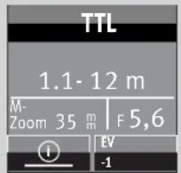
When setting the correction factor, the distance shown in the display can change and be adjusted to the correction factor (depending on the camera model)!
Setting procedure
- Press the EV hsor buttons on the touch display as many times as it takes for the partial light output selection to appear.
- Press the 串 buttons on the touch display and set a correction value.
- Press the selected correction value on the touch display, e.g. -1
The setting will take effect immediately. Manual flash exposure correction is only possible in TTL flash mode if the camera supports this function (consult the camera's operating instructions)!
If the camera does not support this function, the adjusted correction will have no effect.
For some camera models, the manual flash exposure corrections must be adjusted on the camera. If this is the case, no correction value will appear on the flash unit display.
After the shot, remember to cancel the manual flash exposure correction in the camera!

Strongly reflecting objects in the motif can have a negative impact on the camera's automatic exposure. The photograph will be underexposed. Remove reflecting objects or set a positive correction value.
9 Special functions
Depending on the camera model or camera group, various special functions are available.
For this purpose, data exchange must first occur between the flash unit and camera to access and set the special functions, for example by tapping the shutter release.
The setting must occur immediately after accessing the special functions since otherwise the flash unit automatically switches back to normal flash operation after a few seconds!
9.1 Motor zoom reflector (.,Zoom")
The motor zoom reflector of the flash unit can illuminate lens angles from 24mm (35 mm format).
Thanks to the use of the integrated wide-angle diffuser ⑨ , the illumination widens to 12mm .
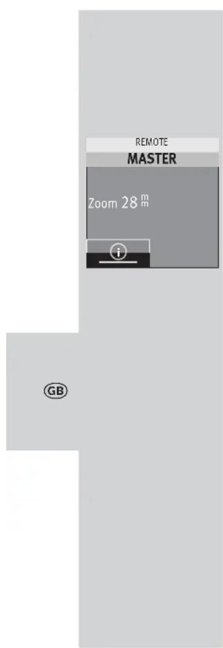
Auto zoom
The zoom position of the reflector is automatically adjusted to the lens focal length when the flash unit is used with a camera that transmits the data related to the lens focal length. After the flash unit has been switched on, "Zoom" and the current zoom position of the reflector are shown in the display.
Automatic adjustment occurs for lens focal lengths from 24mm
The automatic adjustment will not be activated if the reflector is swivelled, if the wide-angle diffuser ⑨ is pulled out, or a Mecabounce (accessory) is mounted.
If so desired, the position of the reflector can be manually adjusted in order to achieve particular lighting effects (such as spot effect etc.).
Manual zoom mode
The zoom position of the reflector must be adjusted manually to the lens focal length when used with a camera that doesn't transmit the data related to the lens focal length.
In this case auto-zoom mode is not possible!
After switching on the flash unit, „Zoom“ appears in the display and the current zoom position of the reflector appears.

Wide-angle diffuser
With the wide angle diffuser 9, focal lengths of 12mm or more can be illuminated (35 mm format).
Pull the wide-angle diffuser ⑨ out from the reflector as far as it will go, and then release it.
The wide-angle diffuser ⑨ automatically folds downwards. The reflector automatically moves to the required position.
The distance readings and the zoom value are corrected to 12mm on the display panel. The automatic adjustment of the motor-zoom reflector (9) is not activated if the wide-angle diffuser is in use.
To insert the wide-angle diffuser ⑨ , turn it upwards 90^ and push it all the way in.
mecabounce Diffuser MBM-03
If the mecabounce (optional accessories, see 19) is fitted to the reflector of the flash unit, the reflector is automatically guided to the position required. The distance data and zoom factor are corrected to 16mm .

The automatic adjustment of the motor-zoom reflector is not activated if the mecabounce is in use.
The simultaneous use of the wide-angle diffuser and the mecabounce is not possible.
10 Cordless flash mode
The flash unit is compatible as a slave flash unit with the wireless Olympus RC flash system (RC=remote control or remote mode). The remote system consists of a master flash unit on the camera and one or more slave flash units. The slave flash unit(s) are controlled via wireless technology by the reflector of the master flash unit.
The slave flash unit is assigned to one of three possible groups (A, B or C). Each group can in turn consists of one or more slave flash units.
The entire remote system can be operated either with mT
A change to the type of flash mode must be made on the master.
There are four independent remote channels to use so that multiple remote systems in the same room do not interfere with one another. Master and Slave flash units belonging to the same remote system must be set to the same remote channel.
The slave flash units must be able to receive the light from the master flash unit with the integrated Sensor for cordless remote control ④.
Remote flash mode also supports second curtain synchronisation. In remote flash mode, the maximum flash range is not indicated on the flash unit's display panel.

10.1 Remote master mode settings
RC mode is in general set on the camera. If the master flash unit is deactivated, it only controls the slave units and does not contribute to exposing the shot.
10.1.1 Remote master mode settings
- Switch on the flash unit with the button.
The start screen appears. - Set RC mode on the camera.
Remote master mode is shown in the picture.
10.1.2 Remote channel settings
There are four independent remote channels to use so that multiple remote systems in the same room do not interfere with one another. Master and Slave flash units belonging to the same remote system must be set to the same remote channel.
The RC mode must be set on the camera and is transmitted to the flash units involved after a test flash.
10.2 Remote slave flash mode
The flash unit supports Olympus's wireless TTL Remote System in slave flash mode. At the same time, one or more slave flash units can be remotely controlled from one master flash unit on the camera (e.g. mecablitz 64 AF-1 O digital).
A slave flash unit can be assigned to one of three possible slave groups (GROUP A, B or C). The master flash unit can control all of these slave groups simultaneously and at the same time take the settings for each slave group into account.
So that multiple remote systems in the same room do not interfere with one another, there are four independent remote channels available (CH 1, 2, 3 or 4).
Master and slave flash units belonging to the same remote system must be set to the same remote channel.
The slave flash units must be able to receive the light from the master flash unit with the integrated sensors for the remote mode.
Depending on the camera model, the camera's internal flash unit can also function as master flash unit.
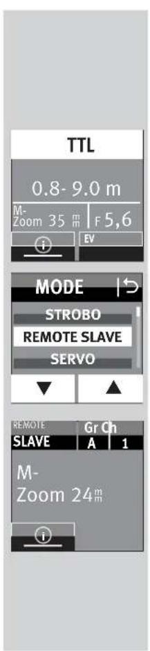
10.2.1 Remote slave flash mode settings
- Switch on the flash unit with the ① ② button. The start screen appears. Thereafter, the flash unit always switches on with the mode of operation that was used last (e.g. TTL flash mode).
-
Press the displayed mode of operation on the touch display as many times as it takes for the display for selecting the mode of operation to appear.
-
Press the s. buttons on the touch display and select REMOTE SLAVE
Press the REMOTE SLAVE on the touch display. Remote slave mode is set.
In addition, the selected slave group (e.g. A) and the remote channel (e.g. CH 1) are displayed.
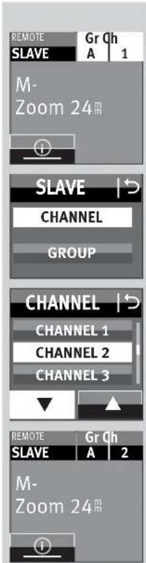
10.2.2 Setting the slave channel
- Press the sensor button on the touch display for the channel group (e.g. GrA I Ch1). The window for selecting the channel and group appears.
- Press the sensor buttons on the touch display for the channel CHANNEL
- Press the 品 buttons on the touch display and select the desired channel.
- Press the selected channel on the touch display.
The setting will take effect immediately. "CH2" appears on the display.

10.2.3 Setting the slave group
- Press the sensor button on the touch display for the channel group (e.g. GrA1Gn2). The window for selecting the channel and group appears.
- Press the sensor button on the touch display for the group GROUP
- Press the 1s 3 buttons on the touch display to select the desired group "A", "B" or "C".
- Press the sensor button on the touch display for the selected group, e.g. GROUP B
The setting will take effect immediately. "B" appears on the display
10.3 Testing remote flash mode
- Place the slave flash units in the desired positions for the shot. Use flash unit mounting foot S60 (optional accessories) to set up the slave flash unit.
- Wait for all of the flash units involved to become flash ready. Once the slave flash units are flash ready, the AF auxiliary light will blink.
Take a test shot and check whether the slave flash unit(s) respond. - If the slave flash unit does not flash, correct the position of the slave flash unit so that it can receive the light from the controller flash unit or reduce the distance between the controller flash unit and the slave flash unit.
- Following the successful completion of the flash test, you can start taking shots.
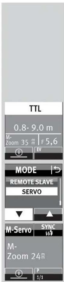
10.4 SERVO mode
SERVO mode is a simple slave mode without or with complete pre-flash suppression in which the slave flash unit always triggers a flash as soon as the camera flash unit receives a light pulse.
In SERVO mode, only manual flash mode is possible. Manual flash mode is automatically activated after switching to SERVO mode.
10.4.1 Setting SERVO flash mode
- Press the sensor button of the displayed mode of operation on the touch display as many times as it takes for the display for selecting the mode of operation to appear.
- Press the 📦 🐽 🤭 🌩 🁷 🍼 on the touch display and select SERVO
Press the SERVO button on the touch display. The mode of operation is adopted.
If desired, partial light output can be set, see 10.4.3.
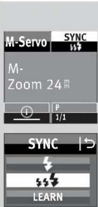
10.4.2 Pre-flash suppression or synchronisation settings
- Press the sensor button SYNC e touch display as many times as it takes for the display for selecting the type of synchronisation.
- Press the sensor button on the touch display: synchronisation without pre-flash synchronisation with pre-flash The synchronisation of operation is adopted.
If the synchronisation set here does not work properly, then proceed as described in 10.4.4.

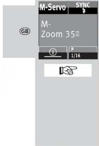
10.4.3 Servo mode partial light output settings
- Press the sensor button P partial light output on the touch display as many times as it takes for the partial light output display to appear.
- Press sensor buttons to touch display and set the desired partial light output to 1/1, 1/2, 1/8 to 1/256.
- Press the sensor button on the touch display for the selected partial light output 1/16 (e.g. 1/16).
The partial light output is adopted.
Once the slave flash units have achieved flash-readiness, the AF measurement flash flashes.
Slave groups and remote channels cannot be set in SERVO mode.
The camera flash unit may not work in the remote mode.
10.4.4 Learn function (LEARN)
The "Learn function" enables individual automatic adjustment of the slave flash unit to the flash technology of the camera's flash unit.
In the process, one or more pre-flashes, e.g. to reduce the "red-eye effect" of the camera flash unit can be taken into account.
The slave flash unit is then fired to coincide with the main flash that illuminates the actual picture.
If the camera's own flash device provides for automatic focussing AF measuring flashes, then due to the system characteristics no learn operation is possible.
If possible, use another camera mode or change to manual focussing.
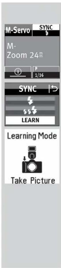
Setting procedure for the learn function
The AF pre-flash function of the camera must be switched off.
- Press the SYNC or buttons on the touch display as many times as it takes for the selection to appear.
Press the LEARN or button on the touch display. - "Learning Mode" is ready to learn.
- Press the release button on the camera so that the camera's own flash unit is activated.
If the SERVO flash unit has received a light pulse, then "LEARN OK" appears in the display as confirmation.
The macablitz digital has learned the flash of the camera flash unit.
10.4.5 Switching-off SERVO flash mode
- Press the displayed mode of operation on the touch display as many times as it takes for the display for selecting the mode of operation to appear.
Press the F s A buttons on the touch display and select the desired mode of operation, e.g. TL
Press the sensor button on the touch display for the mode of operation, e.g.
The selected mode of operation is adopted.
11 OPTION menu
11.1 RAPID mode
In flash modes A and TTL, the recycling times depend on how much light is needed for the exposure. If the recycling time is too long, the RAPID function can be switched on in the A and TTL flash modes. The RAPID function is recommended especially in cases where fast recycling times are more important and maximum flash
output is less important, such as in relatively small spaces. However, the guide number is reduced by 1 level, e.g. from a guide number of 36 (at ISO 100 zoom 35) to guide number 25 (at ISO 100 zoom 35).
Setting procedure
- Press the button as often as it takes for the selection menu to appear.
- Press the OPTION button on the touch display.
- Press the buttons on the touch display and select RAPID
- Press the RAPID button on the touch display.
Press the ofo on the touch display and switch the RAPID function on or off.
The setting is adopted immediately.
After activation of the RAPID function, appears in the display.

OPTION
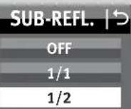
11.2 Secondary reflector (SUB-REFL.)
The secondary reflector is used for frontal brightening when using a bounce flash if the main reflector is tilted sideways or upwards. If the light from the secondary reflector is too large, it can be reduced by half.
Setting procedure
- Press the 2 button as often as it takes for the selection menu to appear.
- Press the OPTION button on the touch display.
- Press the s按钮 on the touch display and select SUB-REFL.
- Press the SUB-REFL tton on the touch display.

Pres

m = 311 ;

3
sensor
ton on the touch display and switch the secondary reflector on or off. The setting is adopted immediately.
Upon switching on the secondary reflector, appears on the display
1/1 or 2/2 is displayed in the INFO menu.
1/1 means full light output, 1/2 means half light output.
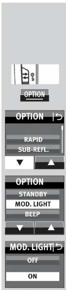
11.3 Modelling light (MOD.LIGHT)
The modelling light is a high-frequency stroboscopic flash. It creates the impression of a semi-permanent light for a duration of about 3 seconds. The modelling light enables the user to assess light distribution and the formation of shadows before taking pictures. The modelling light is triggered with the manual firing button (6).
Setting procedure
- Press the button as often as it takes for the selection menu to appear.
-
Press the OPTION button on the touch display.
-
Press the s buttons on the touch display and select MOD.LIGHT
-
Press the MOD, LIGHT button on the touch display.
-
Press the tens OFF button on the touch display and switch the modelling light on or off. The setting is adopted immediately.
After activation of the modelling light, " appears in the INFO menu.
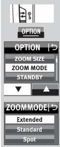
11.4 Zoom Mode (ZOOM MODE)
11.4.1 Extended Zoom Mode
In extended zoom mode the zoom position of the reflector is reduced to one level below the focal length of the camera lens. The resulting expanded and broader light coverage provides additional dispersed light (reflections) inside rooms so that a softer flash illumination is possible.
Example:
The focal length of the camera lens is 50mm The extended zoom mode sets a 35~mm reflector position on the flash unit. However, 50~mm continues to be shown on the display.
Setting procedure
- Press the 2 button as often as it takes for the selection menu to appear.
- Press the OPTION button on the touch display.
-
Press the buttons on the touch display and select ZOOM MODE
-
Press the ZOOM MODE often as it takes for the selection menu to appear.
- Press the EXTENDED button on the touch display.
The setting is adopted immediately. After activation of extended zoom mode, "EXT" appears in the INFO menu. Depending on the system, the extended zoom mode is supported for lens focal lengths of 28mm or more (35-mm format)
The camera must be equipped with a CPU lens and be able to transfer data on the lens focal length to the flash unit.
11.4.2 SPOT zoom mode
In spot zoom mode, the zoom position of the reflector is increased by one level compared to the focal length of the camera lens. The resulting reduced illumination provides centre-weighted illumination or alternatively shadowy edge lighting.
Example:
The focal length of the camera lens is 50mm . The spot zoom mode sets a 70~mm reflector position on the flash unit. However, 50~mm continues to be shown on the display.

OPTION
OPTION
ZOOM SIZE
ZOOM MODE
STANDBY


ZOOMMODE
EXTENDED STANDARD
SPOT
Setting procedure
- Press the button as often as it takes for the selection menu to appear.
- Press the OPTION button on the touch display.
- Press the s. a. t. u. n. o. n. on the touch display and select ZOOM MODE
- Press the ZOOM MODEtton on the touch display.
- Press the SPOT button on the touch display. The setting is adopted immediately.
After activation of spot zoom mode, "SP" appears in the INFO menu.
Depending on the system, the spot zoom mode is supported for lens focal lengths of 24mm - 180mm or more (35-mm format).
The camera must be equipped with a CPU lens and be able to transfer data on the lens focal length to the flash unit.

OPTION
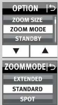
11.4.3 STANDARD zoom mode
In standard zoom mode, the zoom position of the reflector is adjusted to the focal length of the camera lens.
Setting procedure
- Press the 4 button as often as it takes for the selection menu to appear.
- Press the OPTION button on the touch display.
- Press the トtons on the touch display and select ZOOM MODE
Press the ZOOM MODEton on the touch display. - Press the STANDARD button on the touch display. The setting is adopted immediately.

OPTION
OPTION
SUB-REFL.
ZOOM SIZE
ZOOM MODE


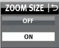


touch display. The setting is adopted immediately.
" appears in the INFO menu after activation of the zoom size function.
once the zoom size function has been deactivated, the symbol will be deleted from the INFO menu.
The Zoom Size function cannot be set with cameras which do not support shooting format adjustment!
11.6 AF auxiliary light (AF-BEAM)
If the AF metering system of a digital AF reflex camera is unable to focus due to insufficient ambient lighting, the camera activates the AF auxiliary light built into the flash unit.
This projects a stripe pattern onto the subject which the camera uses to focus.
With the "AF-BEAM" function, the AF auxiliary light can be switched on or off.
The range is approx. 6m 9m with a standard 1.7 / 50~mm lens). Parallax error between the lens and AF auxiliary light limits the close-up range with the AF auxiliary light to approximately 0.7m to 1m
If the automatic AF auxiliary light 14 is to be activated by the camera, the "Single-AF (S-AF)" autofocus mode must be set on the camera and the flash unit must indicate flash readiness.
Some camera models support only the camera's internal AF auxiliary light. In this case, the automatic AF auxiliary light of the flash unit is not activated (as in the case of compact cameras; see the camera's operating instructions).
Low-speed zoom lenses can significantly curtail the range of the AF auxiliary light!

- Press the button as often as it takes for the selection menu to appear.
- Press the OPTION button on the touch display.
Press the s. buttons on the touch display and select AF BEAM
Press the AF BEAM button on the touch display.
Press the pen off button on the touch display.
The setting is adopted immediately.
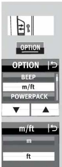
11.7 Range display in m or ft
The range indication in the display can either be shown in metres (m) or feet (ft).
Setting procedure
- Press the button as often as it takes for the selection menu to appear.
- Press the OPTION button on the touch display.
- Press the s buttons on the touch display and select m/ft
Press the m/ft button on the touch display.
Press the m selitbr button on the touch display.
The setting is adopted immediately.
11.8 Flash Bracketing Series (FLASH BRACK.)
A series of flash exposures (flash-bracketing FB) can be carried out in the TTL and automatic flash modes. A flash bracketing series consists of three successive flash shots with different flash exposure correction values.
When a flash bracketing series is set, FB and the correction value appear on the display. The possible correction values range from 1/3 to 3 apertures in onethird aperture increments.
Setting procedure
- Press the button as often as it takes for the selection menu to appear.
- Press the OPTION button on the touch display.
-
Press the buttons on the touch display and select FLASH BRACK.
Press the FLASH BRACK on on the touch display.
Press the s buttons on the touch display and select a correction value. -
Press the sensor button on the touch display for the selected correction value, e.g. 1.
The setting is adopted immediately.
The first shot is taken without a correction value. FB will also appear on the display.
The second shot is taken with minus correction. ^ FB II" and the minus correction value (EV) will also appear on the display.
The third shot is taken with plus correction. "FB III" and the plus correction value (EV) will also appear on the display.
After the third shot, the flash bracketing series is automatically deleted. FB^ will disappear from the display
When the flash bracketing series is set, the correction value is always shown as a positive value!!
Flash bracketing series in the TTL flash mode
A flash bracketing series in the TTL flash mode is only possible if the camera supports the setting of a manual flash exposure correction on the flash unit (see camera instruction manual)! Otherwise, the shots are taken without a correction value!
Flash bracketing in automatic flash mode A
The type of camera is not important for a flash bracketing series in automatic flash mode A.
11.9 Beep function (BEEP)
The beep function allows the user to receive an acoustic signal for certain functions of the flash unit. This allows the photographer to concentrate fully on the subject and taking the picture, and not have to worry about any optical status indicators.
The beep function acoustically signals when the flash is ready or when an error occurs.

OPTION
BEEP

m/ft
BEEP
OFF
ON
Setting procedure
- Press the button as often as it takes for the selection menu to appear.
- Press the OPTION button on the touch display.
- Press the s buttons on the touch display and select BEEP
- Press the BEEP button on the touch display.
- Press the On sor button on the touch display. The setting is adopted immediately.
appears in the INFO menu after activation of the BEEP function.
Acoustic signals after the flash unit has been turned on:
- A short (about two seconds) uninterrupted beep signal after turning the flash on indicates that the flash unit is ready.
Set Beep signals when adjusting automatic mode settings:
- A short beep signal as an alarm in automatic mode indicates that the aperture and ISO settings exceed the permissible light control range. The auto aperture of the mecablitz is then automatically adjusted to the next permissible value.
11.10 Locking / unlocking
The setting on the flash unit can be locked against unintended changes.
To lock or unlock, hold down the
button for approximately 3 seconds.
On the screen, all the sensor buttons are shown in white and can no longer be accessed.
Only the INFO sensor button can be pressed.
11.11 Connecting a power pack (accessory)
A power pack (accessory) can be connected to the flash unit using port 18.
You need a connection cable (special accessory) to connect the power pack.
The power pack extends the operating time of the flash unit and provides faster flash recycling times.

OPTION


AF BEAM

Setting procedure
- Press the button as often as it takes for the selection menu to appear.
- Press the OPTION button on the touch display.
- Press the s. buttons on the touch display and select POWERPACK
- Press the POWERPACK on on the touch display.
- On the touch display, press the sensor button for a very fast recycling time or the sensor button for a fast recycling time.
The setting is adopted immediately.
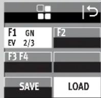
12 Favorite programme
In flash photography there are always recurring standard situations (e.g. birthday celebrations at home, etc.). The ecablitz permits the settings for such standard situations to be stored as a favorite programme so that the selected flash parameters can be instantly reset.
The flash unit has 4 memory locations for saving the settings made on the flash unit.
Procedure for saving a favourite programme
- Set the flash unit parameters.
- Press the button as often as it takes for the selection menu to appear.
-
Press the 1 sor button on the touch display.
-
Press the SAVE button on the touch display.
Press the F1 send F4 button on the touch display.
The settings are saved to the selected memory location.
Procedure for loading a favourite programme


- Press the 7 button as often as it takes for the selection menu to appear.
- Press the hhsor button on the touch display.
- Press the LOAD button on the touch display.
- Press the F1 sen F4 button on the touch display.. The settings are loaded from the selected memory location.
13 Flash techniques
13.1 Bounce flash
Bounce flash illuminates the subject more softly and reduces dense shadows. It also reduces the drop in light from foreground to background that occurs for physical reasons.
The reflector of the flash unit can be swivelled horizontally and tilted vertically for bounce flash.
Tilting the reflector
- Press the release button ② and remove the reflector from the lock while turning it to the desired position.
The reflector is locked only in the normal position.
To avoid colour cast in your shots, the reflective surface should be colour-neutral or white.
When tilting the reflector vertically, make sure that it is turned through an angle that is wide enough to prevent direct light from falling on the subject. For this reason the reflector should be tilted at least as far as the 60^ lock-in position.
When the reflector head is tilted, the reflector is moved to a position of 70mm in order to prevent the subject from being additionally illuminated by dispersed light.
The range and position of the reflector is not displayed.
13.2 Bounce flash with a reflector card
The use of bounce flash with the integrated reflector card ⑧ can bring out highlights in the eyes of human subjects:
- Tilt the reflector head upwards by 90^ .
- Pull the reflector card together with the wide-angle diffuser from above out of the reflector head and forwards.
- Hold the reflector card (8) and push the wide-angle diffuser (9) back into the reflector head.
13.3 Close-ups / macro shots
In close-ups and macro shots, parallax error between the flash unit and lens may result in shadows on the lower edge of the image. To compensate for this, the main reflector can be tilted downwards by an angle of -9^ . To do this, depress the reflector release button ⑫ and tilt the reflector downward.

If the main reflector is tilted downwards, "is shown on the display to indicate this. The second reflector is not supported and does not flash.
Certain minimum lighting distances must be maintained for close-up shots to avoid overexposure.

14 Flash synchronisation
14.1 Automatic flash sync speed control
Depending on the camera model and camera mode, the shutter speed is switched to flash sync speed when flash readiness is reached (see the camera's operating instructions).
Shutter speeds cannot be set faster than the flash sync speed, or they are switched automatically to the flash sync speed. Various cameras have a sync speed range, for example from 1/60 sec to 1/250 sec (see the camera's operating instructions). The sync speed set by the camera depends on the camera mode, the ambient light, and the focal length of the lens used.
Shutter speeds slower than the flash sync speed can be set according to the camera mode and the selected flash synchronisation.
If a camera with a between-the-lens shutter and high-speed synchronisation (see 7.4) is used, flash sync speed is not controlled automatically. As a result, the flash can be used at all shutter speeds. If you need the full light output of the flash unit, you should not select a shutter speed that is any faster than 1/125 sec.
14.2 Normal synchronisation
In normal synchronisation the flash unit is triggered at the beginning of the shutter time (first curtain synchronisation). Normal synchronisation is the standard mode on all cameras. It is suitable for most flash shots. The camera, depending on the mode being used, is switched to the flash sync speed.
Speeds between 1/30 sec. and 1/125 sec. are customary (see the camera's operating instructions).
No settings are necessary on the flash unit, nor is there any display for this mode.
14.3 Slow synchronisation (SLOW)
A slow exposure (SLOW) gives added prominence to the image background at lower ambient light levels. This is achieved by adjusting the shutter speed to the ambient light. Accordingly, shutter speeds that are slower than the flash sync speed (e.g., shutter speeds up to 30 sec.) are automatically adjusted by the camera. Slow synchronisation is activated automatically on some camera models in connection with certain camera programs (e.g., a night shot program, etc.), or it can be set on the camera (see the camera's operating instructions). No settings are necessary on the flash unit, nor is there any display for this mode.
Slow synchronisation SLOW is set on the camera (see camera's operating instructions)! Use a tripod when shooting with slow shutter speeds to avoid blurred images!
14.4 Second curtain synchronisation (REAR)
Some cameras offer the option of secondcurtain synchronisation (REAR), in which the flash unit is not triggered until the end of the exposure time.
This is particularly advantageous when used with lower shutter speeds (slower than 1/30 sec.) and moving subjects that have their own source of light. With second-curtain synchronisation, a moving light source will trail a light streak instead of building one up ahead itself, as it does when the flash is synchronised with the first shutter curtain. In this way a "more natural" image of the photographic situation is produced!
Depending on its operating mode, the camera sets shutter speeds slower than its sync speed.
On some cameras the REAR function is not possible in certain operating modes (e.g., certain vari- or subject programs, or with red eye reduction). In these cases, the REAR mode cannot be selected and/or is automatically cancelled or ignored (see camera's operating instructions).
The REAR mode is set on the camera (see camera's operating instructions).

14.5 Synch socket
The flash can be triggered in automatic flash mode A manual flash mode a strobe flash mode via the sync socket.
An old flash unit with high-voltage ignition system may not be connected to the sync socket.
16 Care and maintenance
- The screen surface should only be cleaned with a soft, dry cleaning cloth (e.g. microfibre cloth).
- If significant soiling nevertheless occurs, the screen surface can be cleaned with a slightly moist soft cloth.
Never spray cleaning fluid on the surface of the screen! If cleaning fluid penetrates into the frame of the screen, the components there will be damaged beyond repair.
16.1 Firmware updates
The firmware version (V.10 in the example) of the flash unit is shown in the start screen after switching on.
The flash unit's firmware can be updated through the USB port (1) and adjusted to the technical requirements of future cameras (Firmware Update).
For more information, visit the Metz homepage at www.metz-mecatech.de.

SERVICE

BRIGHTNESS
ROTATION
RESET

OFF
ON
16.2 Conditioning the flash capacitor
The flash capacitor built into the flash unit undergoes a physical change when the device has not been used for a long time. For this reason it is necessary to switch the device every three months for approx. 10 mins. The power supplies must deliver enough power so that flash standby lights up no later than 1 min after switching on.
16.3 Factory settings (RESET)
The flash unit can be reset to the factory settings when delivered.
Setting procedure
- Press the ⑦ button as often as it takes for the selection menu to appear.
- Press the SERVICE button on the touch display.
- Press the RESET button on the touch display.
- Press the ON or button on the touch display. All settings are adopted immediately at the flash unit is reset to its factory set
This will not affect the firmware updates for the flash unit!
17 Troubleshooting
Should the flash unit fail to function properly or meaningless content appear on the flash unit display panel, switch the flash unit off with the main switch (2) for approximately 10 seconds. Check the camera settings and make sure the foot of the flash unit is mounted correctly in the camera's accessory shoe.
Replace the batteries with new or freshly charged batteries.
The flash unit should function normally again once it is switched back on. If this is not the case, contact your local dealer.
Below is a list of some of the problems that may occur when the flash unit is used. For each item, possible causes and remedies for the problem are listed.
No maximum flash range indication appears on the display panel.
- There has been no exchange of data between the flash unit and the camera.
Tap the camera's shutter release. - The reflector is not in normal position.
- The flash unit has been set to remote operation.
The AF measuring beam of the flash unit is not activated.
The flash unit is not ready for firing.
The camera is not in „Single-AF (S-AF)" mode.
- The camera supports only its own internal AF measuring beam.
- Some cameras support the AF measuring beam in the flash unit only with the camera's central AF sensor. If a peripheral AF sensor is selected, then the AF measuring beam will not be activated in the flash unit.
Activate the central AF sensor.
- The "AF BEAM" is switched off. Switch on "AF BEAM", see 11.6
The reflector position is not automatically adjusted to the current zoom position of the lens.
- The camera does not transfer data to the flash unit
- There is no exchange of data between the flash unit and the camera.
Tap the camera's shutter release.
- The camera is equipped with a lens without CPU.
- The flash unit operates in manual zoom mode „MZoom".
Switch to Auto-Zoom (see 11.4.3)
- The reflector is swivelled out of its locked normal position.
- The wide-angle diffuser folds out from the reflector.
- A Mecabounce is mounted in front of the reflector.
The aperture setting on the flash unit is not automatically adjusted to that of the lens.
- The camera does not transfer data to the flash unit
- There is no exchange of data between the flash unit and the camera.
Tap the camera's shutter release.
- The camera is equipped with a lens without CPU.
Automatic switching to the flash sync speed fails to occur.
- The camera has a between-the-lens shutter (as do most compact cameras), Switching to sync speed is therefore unnecessary.
- The camera operates with high-speed synchronisation HSS (camera settings). Switching to sync speed does not occur in the process.
- The camera operates with shutter speeds that are slower than the flash sync speed. Depending on the camera mode, there is no switch to flash sync speed (see the camera's operating instructions).
The shots are too dark.
The subject is beyond the range of the flash unit. Note: Using bounce flash reduces the range of the flash unit.
- The subject contains very bright or highly reflective areas. The metering system of the camera or flash unit is deceived as a result. Set a positive manual flash exposure correction, e.g., +1 EV.
The shots are too bright.
- In close-up shots, overexposure (shots that are too bright) may result if the shutter speed is faster than the flash sync speed.
The aperture (f-stop) cannot be adjusted on the flash unit.
- There is an exchange of digital data between the flash unit and camera. Adjustment of the aperture is not possible!
18 Technical data
Max. guide numbers at ISO 100/21°, zoom 200 mm:
In the metric system: 64
In the imperial system: 210
Flash modes:
TTL, TTL FP flash mode, manual flash mode, M FP flash mode, automatic A, strobe flash mode, Remote slave flash mode, Servo mode.
automatic aperture setting at ISO 100/21°:
F1.4 to F64, including intermediate values
Manual partial light output levels:
P1/1... P1/ 256 in one-third increments.
P1/1 . . . P1/256 light output, in automatic high-speed synchronisation (HSS)
Flash durations: see table 2, page (Page 291)
Colour temperature: Ca. 5600 K
Sensitivity to light: ISO 6 to ISO 51200
Synchronisation:
low-voltage ignition
Number of flashes
140 with alkali-manganese-batteries (1,5V)
- 190 with NiMH rechargeable batteries (1,2V / 2100 mAh)
290 with lithium batteries (1,5V)
360 with Metz Power Pack P76
Recycling times in sekc (min./max.)
- 0,1/4,4 with alkali-manganese-batteries (1,5V)
- 0,1/1,8 with NiMH rechargeable batteries (1,2V / 2100 mAh)
- 0,1/4,2 with lithium batteries (1,5V)
0,1/1,6 with Metz Power Pack P76
Light coverage:
Reflector from 24mm (35 mm format)
Reflector with wide-angle diffuser from 12 mm (35 mm format)
Swivelling ranges and locking positions of the reflector:
upwards: 45^ 60^ 75^ 90^
counter-clockwise:
60^90^120^150^180^
clockwise:
60^90^120^
Dimensions, approx., in mm (W x H x D):
Ca. 78 × 148 × 112
Weight :
Flash unit without batteries approx. 422g
Included:
Flash unit with integrated wide-angle diffuser, operating instructions, Flash unit mounting foot S60, Belt pouch T64, operating instructions.
19 Optional accessories
We accept no liability for malfunctions of or damage to the flash unit caused by the use of accessories of other manufacturers!
- mecabounce Diffuser MBM-03
(Order No. 000003902)
With this diffuser, soft lighting can be achieved in a very simple manner. It gives your pictures a marvellous soft appearance. Skin tones are captured more faithfully.
The maximum working range is reduced by about half in conformity with the loss of light.
- Bounce diffuser 58-23
(Order No. 000058235)
Softens heavy shadows with reflected light.
- Flash unit mounting foot S60
(Order No. 000000607)
Flash unit mounting foot for slave mode.
- Connecting cable V58-50
(Order No. 000058504)
also fits power pack P76
Powerpack
Easy Softbox ESB 60-60
(Order No. 009016076)
Dimensions: 60 × 60 cm
Including front and background diffusers, carrying case and Bowens-compatible adapter to connect to a Metz TL or BL studio flash device
Easy Softbox ESB 40-40
(Order No. 009014047)
Dimensions: 40 × 40 cm
Including front and background diffusers, carrying case and
Bowens-compatible adapter to connect to a Metz TL or BL studio flash device
- Flash device holder FGH 40-60
(Order No. 009094065)
Adapter for compact flash devices and Easy Softboxes
Adjustable flash foot height
Connects to Metz lighting tripods LS-247 and LS-200
- Mini Softbox SB 30-20
(Order No. 009013023)
Colour: white, Dimensions: 30 × 20 cm
- Mini Softbox SB 22-16
(Order No. 009012217)
Colour: white, Dimensions: 22 × 16 cm
- Mini Softbox SB 18-15
(Order No. 009011817)
Colour: white, Dimensions: 18 × 15 cm
- Mini Octagon Softbox SB 34-34
(Order No. 009023432)
Colour: white, Dimensions: 0.34 cm
- Mini Octagon Softbox SB 20-20
(Order No. 009022029)
Colour: white, Dimensions: 20cm
- Mini Octagon Softbox SB 15-15
(Order No. 009021516)
Colour: white, Dimensions: 0.15 cm - Spot bounce diffuser SD 30-26 W
(Order No. 009043021)
Colour: white for neutral light / Dimensions: 30 × 26 cm
- Spot bounce diffuser SD 30-26 S
(Order No. 00904303A)
Colour: silver for cool light / Dimensions: 30 × 26 cm
- Spot bounce diffuser SD 30-26 G
(Order No. 009043048)
Colour: gold for warm light / Dimensions: 30 × 26 cm
- TTL connecting cable for Olympus TCC-30
(Order No. 000305134)
The 1.8m long TTL connection cable for compact flash devices provides full TTL lighting control. Equipped with a tripod socket.
Disposal of batteries
Do not dispose of spent batteries with domestic rubbish.
Please return spent batteries to collecting points should they exist in your country!
Please return only fully discharged batteries.
Normally, batteries are fully discharged if:
-
the device they powered switches itself off and indicates "Spent Batteries".
-
they no longer function properly after prolonged use.
To ensure short-circuit safety please cover the battery poles with adhesive tape.

ZOOM MODE (illumination), cap. 11.4
In all operating modes, the brightness of the screen is reduced by 50 per cent after approx. 10 seconds to save energy. The screen brightness is restored again whenever a button or a symbol on the screen is pressed.

OPTION
ZOOM MODE
STANDBY
MOD.LIGH


OFF
1 min
10 min
Easy Softbox ESB 40-40
art.no.009014047
Misure: 40 × 40 cm
m / ft (metros/pies), consultar 11.7
POWERPACK (Powerpack externo),
consultar 11.11
AF BEAM (luz auxiliar AF), consultar 11.6
(N ^9 ref. 009016076)
Dimensiones: 60 × 60 cm
Easy Softbox ESB 40-40
(N*ref.009014047)
Dimensiones: 40 × 40 cm
(N ^g ref. 009012217)
Color: blanco, dimensiones: 22 × 16 cm
- Mini Softbox SB 18-15
(N* ref. 009011817)
Color: blanco, dimensiones: 18 × 15 cm
- Mini Octagon Softbox SB 34-34
(N ^o ref. 009021516)
Color: blanco, dimensiones: 0 15 cm
- Spot Reflexschirm SD 30-26 W
(N*ref.009043021)
Color: blanco para luz neutral / dimensiones: 30 × 26 cm
- Spot Reflexschirm SD 30-26 S
(N ^圆 ref. 00904303A)
Your Metz product was developed and manufactured with high-quality materials and components which can be recycled and/or re-used.
This symbol indicates that electrical and electronic equipment must be disposed of separately from normal garbage at the end of its operational lifetime.
Please dispose of this product by bringing it to your local collection point or recycling centre for such equipment. This will help to protect the environment in which we all live.

Metz - always first class.

C
D F NL GB I E


- mecablitz 64 AF-1 digital
- Rotation (ROTATION)
- Easy Softbox ESB 40-40
- Gewicht :
- Declaration
- Proper Use
- Safety instructions
- Dedicated flash functions
- Preparing the flash unit for use
- Mounting the flash unit
- Mounting the flash unit on the camera
- Power supply
- Suitable batteries/rechargeable batteries
- Replacing batteries
- INFO
- Auto OFF for the flash unit
- LED displays on the flash unit
- Flash readiness indication
- Correct exposure indication
- Information in Display
- Display illumination
- Display of the flash mode
- Range display
- The flash range is not displayed when . . .
- Range display in TTL-
- TTL FP- flash modes
- Range display in manual flash mode M
- Exceeding the display range
- Displays in the camera viewfinder
- Flash symbol flashes
- Flash symbol is illuminated
- Incorrect exposure guidelines:
- Flash modes
- TTL flash mode (TL)
- Setting the mode of operation
- Automatic TTL Fill-in flash mode
- Ensure that the contre-jour light source does not shine directly into the lens, as this will interfere with the camera's TTL metering system!
- Manual flash mode
- Manual partial light output levels
- Setting procedure
- Automatic high-speed synchronisation (FP)
- Automatic flash mode
- Strobe flash mode
- Strobe number of flashes (N)
- Strobe flash frequency (f)
- Set number of flashes (N)
- Setting the flash frequency (f(Hz))
- Manual flash exposure correction
- Tip:
- Light subject against dark background: negative correction factor.
- Special functions
- Motor zoom reflector (.,Zoom")
- Auto zoom
- Manual zoom mode
- In this case auto-zoom mode is not possible!
- Wide-angle diffuser
- mecabounce Diffuser MBM-03
- Cordless flash mode
- Remote master mode settings
- Remote master mode settings
- Remote channel settings
- Remote slave flash mode
- Remote slave flash mode settings
- Setting the slave channel
- Setting the slave group
- Testing remote flash mode
- SERVO mode
- Setting SERVO flash mode
- Pre-flash suppression or synchronisation settings
- Servo mode partial light output settings
- Learn function (LEARN)
- Setting procedure for the learn function
- Switching-off SERVO flash mode
- OPTION menu
- RAPID mode
- Secondary reflector (SUB-REFL.)
- Modelling light (MOD.LIGHT)
- Zoom Mode (ZOOM MODE)
- Extended Zoom Mode
- Example:
- SPOT zoom mode
- STANDARD zoom mode
- AF auxiliary light (AF-BEAM)
- Range display in m or ft
- Flash Bracketing Series (FLASH BRACK.)
- Flash bracketing series in the TTL flash mode
- Flash bracketing in automatic flash mode A
- Beep function (BEEP)
- Acoustic signals after the flash unit has been turned on:
- Set Beep signals when adjusting automatic mode settings:
- Locking / unlocking
- Connecting a power pack (accessory)
- Favorite programme
- Procedure for saving a favourite programme
- Procedure for loading a favourite programme
- Flash techniques
- Bounce flash
- Tilting the reflector
- The reflector is locked only in the normal position.
- Bounce flash with a reflector card
- Close-ups / macro shots
- Flash synchronisation
- Automatic flash sync speed control
- Normal synchronisation
- Slow synchronisation (SLOW)
- Second curtain synchronisation (REAR)
- Synch socket
- Care and maintenance
- Firmware updates
- Conditioning the flash capacitor
- Factory settings (RESET)
- Troubleshooting
- No maximum flash range indication appears on the display panel.
- The AF measuring beam of the flash unit is not activated.
- The aperture setting on the flash unit is not automatically adjusted to that of the lens.
- Automatic switching to the flash sync speed fails to occur.
- The shots are too dark.
- The shots are too bright.
- The aperture (f-stop) cannot be adjusted on the flash unit.
- Technical data
- Flash modes:
- Manual partial light output levels:
- Synchronisation:
- Number of flashes
- Recycling times in sekc (min./max.)
- Light coverage:
- Swivelling ranges and locking positions of the reflector:
- Weight :
- Included:
- Optional accessories
- - mecabounce Diffuser MBM-03
- - Bounce diffuser 58-23
- - Flash unit mounting foot S60
- - Connecting cable V58-50
- Powerpack
- Easy Softbox ESB 60-60
- - Flash device holder FGH 40-60
- - Mini Softbox SB 30-20
- - Mini Softbox SB 22-16
- - Mini Softbox SB 18-15
- - Mini Octagon Softbox SB 34-34
- - Mini Octagon Softbox SB 20-20
- Disposal of batteries
Brand : METZ
Model : Mecablitz 64 AF1 digital
Category : Flash