Mecablitz 52 AF1 Olympus digital - Flash METZ - Free user manual and instructions
Find the device manual for free Mecablitz 52 AF1 Olympus digital METZ in PDF.

| Product Type | Electronic flash for Olympus, Panasonic, and Leica cameras (FourThirds/Micro-FourThirds system) |
| Dimensions (H x W x D) | Approx. 73 × 134 × 90 mm |
| Weight | Approx. 346 g (without batteries) |
| Power Supply | 4 AA batteries (alkaline, lithium) or NiMH rechargeable batteries 1.2 V (type HR6) |
| Maximum Guide Number (ISO 100/21°, 105 mm) | 52 (meters) / 170 (feet) |
| Flash Modes | TTL, TTL FP (high-speed sync), Manual (M), M FP, Remote Slave, Servo |
| Flash Exposure Compensation | From -3 EV to +3 EV in 1/3 EV steps |
| Manual Partial Power | From P 1/1 to P 1/128 |
| Motorized Zoom Head | From 24 mm to 105 mm (35mm film); built-in wide-angle diffuser for 12 mm |
| Zoom Modes | Auto, manual, extended, spot, standard |
| Sync | Normal (1st curtain), slow speed (SLOW), 2nd curtain (REAR), high speed (FP) |
| Wireless Multi-Flash | Remote master/slave mode; 4 channels, 3 groups (A, B, C) |
| Modelling Light | Yes, series of high-frequency stroboscopic flashes (duration ~3 s) |
| AF Assist Light (AF Beam) | Yes, range of 6 to 9 m (standard 50mm lens) |
| Firmware Update | Via USB port |
| Color Temperature | Approx. 5600 K |
| Head Tilt/Swivel | Vertical: -10° to +90° (stops at 45°, 60°, 75°, 90°); Horizontal: 180° to the right |
| Auto Power Off | Adjustable: Off, 1 min, 10 min; standby after 10 min by default |
| Maintenance and Cleaning | Soft, dry or silicone cloth; do not use detergent |
| Optional Accessories | Mecabounce diffuser MBM-02, reflector screen 58-23, flash stand S60 |
Frequently Asked Questions - Mecablitz 52 AF1 Olympus digital METZ
See 7.1 TTL Operating Modes.
See 7.4 Automatic High-Speed Sync (FP).
User questions about Mecablitz 52 AF1 Olympus digital METZ
0 question about this device. Answer the ones you know or ask your own.
Ask a new question about this device
Download the instructions for your Flash in PDF format for free! Find your manual Mecablitz 52 AF1 Olympus digital - METZ and take your electronic device back in hand. On this page are published all the documents necessary for the use of your device. Mecablitz 52 AF1 Olympus digital by METZ.
USER MANUAL Mecablitz 52 AF1 Olympus digital METZ
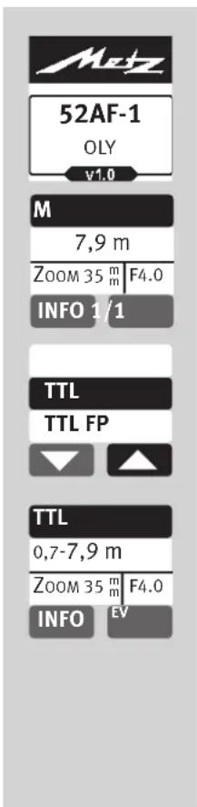
mecablitz 52 AF-1 Olympus digital

Learning Mode
Take Picture
14.2 Brightness (Helligkeit)
AbmaBe in mm (B x H x T):
Ca. 73 × 134 × 90
Gewicht:
14.2 Brightness (Luminosite)
m = 311 ;
M
7,9m
ZOOM35 m F4.0
INFO 1/1
TTL
TTL FP


TTL
0,7-7,9m
ZOOM35m F4.0
INFO

Learning Mode
Take Picture
m = 311
11 OPTION-Menu
11.1 Instellicht
12.1 Indirect flitsen
14.2 Brightness (Helderheid)
Afmetingen ong. in mm (B x H x D):
Ca. 73 × 134 × 90
Gewicht :
1 Safety instructions 132
2 Dedicated flash functions 133
3 Preparing the flash unit for use 134
3.1 Mounting the flash unit 134
3.2 Power supply 135
3.3 Switching the flash unit on and off 136
3.4 The selection menu 136
3.5 INFO 137
3.6 Auto OFF for the flash unit 138
4 LED displays on the flash unit. 139
4.1 Flash readiness indication 139
4.2 Correct exposure indication 139
5 Information in Display 140
5.1 Display of the flash mode 140
5.2 Range display 140
6 Displays in the camera viewfinder 142
7 Flash modes 142
7.1 TTL-flash mode 142
7.2 Automatic TTL Fill-in flash mode 143
7.3 Manual flash mode 144
7.4 Automatic high-speed synchronisation (FP) 145
8 Manual flash exposure correction 146
9 Special functions 147
9.1 Motor zoom reflector (,Z_om^ ) 147
10 Cordless flash mode 150
10.1 Remote master mode settings 150
10.1.1 Remote master mode settings 150
10.1.2 Remote channel settings 150
10.2 Remote slave flash mode 151
10.2.1 Remote slave flash mode settings 151
10.2.2 Setting the slave channel 152
10.2.3 Setting the slave group 152
10.3 Testing remote flash mode 153
10.4 SERVO mode 153
10.4.1 Setting SERVO flash mode 153
10.4.2 Pre-flash suppression or synchronisation settings .154
10.4.3 Servo mode partial light output settings 154
10.4.4 Learn function 155
10.4.5 Switching-off SERVO flash mode 156
11 OPTION menu. 156
11.1 Modelling light 156
11.2 Zoom Mode 157
11.2.1 Extended Zoom Mode 157
11.2.2 SPOT zoom mode 157
11.2.3 STANDARD zoom mode 158
11.2.4 Shooting format adjustment (Zoom-Size) 159
11.3 AF-BEAM (AF auxiliary light) 159
11.4 Locking / unlocking 160
11.5 Range display in m or ft 160
12 Flash techniques 161
12.1 Bounce flash 161
12.2 Bounce flash with a reflector card 161
13 Flash synchronisation 162
13.1 Automatic flash sync speed control 162
13.2 Normal synchronisation 162
13.3 Slow synchronisation (SLOW) 162
13.4 Second curtainsinchronisation (REAR) 163
14 Touch display settings 164
14.1 Contrast 164
14.2 Brightness 164
14.3 Rotation 165
15 Care and maintenance. 166
15.1 Firmware-Update 166
15.2 Conditioning the flash capacitor 166
15.3 Reset 166
16 Troubleshooting 167
17 Technical data 170
18 Optional accessories 171
Introduction
Thank you for choosing a Metz product. We are delighted to welcome you as a customer. You will of course be impatient to start using the flash unit.
However, it is worthwhile reading the operating instructions and learning how to use the unit correctly.
This flash unit is suited for:
- Olympus - Digital cameras with TTL flash control and flash socket system, as well as the compatible digital cameras from Panasonic and Leica.
This flash unit is not suited for other brands of cameras!
Take a look at the diagrams at the end of the manual.
Declaration
Tip, note
Attention - Extremely important safety information!
GB
1 Safety instructions
The flash unit may in no event be activated in the vicinity of inflammable gases or liquids (petroleum, solvents etc.). RISK OF EXPLOSIONS!
Do not flash directly into eyes from a close distance! Direct flashing into the eyes of persons or animals can cause damage to the retina and severe disruption of the vision - up to and including permanent blindness!
Never use a flash unit to photograph car, bus, bicycle, motorbike or train drivers while they are driving. Blinding the driver can lead to an accident!
If the housing has been damaged in such a way that internal components are exposed, the flash unit may no longer be used. Remove the batteries! Do not touch any internal components. HIGH VOLTAGE!
After repeated flashing, do not touch the diffuser. Risk of burns!
Do not dismantle the flash unit! HIGH VOLTAGE! Repairs should only be performed by authorised service personnel.
The flash unit is exclusively designed and authorised for use in photographic applications!
- Only use the power sources designated and autho-rised in the operating manual!
- Do not open the batteries or short them!
- In no event the batteries be exposed to high temperatures like direct sunlight, fire or similar!
- Never throw flat/dead batteries onto a fire!
- Do not use any toxic batteries or rechargeable batteries!
- Remove the used batteries immediately from the device! Chemicals can escape from used batteries (so-called "leaks") resulting in damage to the device.
- Batteries may not be recharged.
- Do not expose the flash unit to water drops and splashes!
- Protect your flash unit from heat and high air humidity! Do not keep it in the glove compartment of your car!
Rapid changes in temperature may lead to condensation. If this occurs, allow time for the unit to become acclimatized!
- When you activate the flash, there should be no opaque material directly in front of or on the reflector cover (flash window). The intense energy emissions can otherwise lead to scorching or spotting of the material and/or the reflector cover.
After a series of flashes with full power and short intervals, a pause of at least 3 minutes must be observed after each series of 20 flashes! - When taking a series of flash shots at full light output and with rapid recycling times, and with zoom positions of 35mm and less, the diffuser heats up, due to the high level of thermal energy.
- This flash unit may be used in combination with a camera-integrated flash only if the flash can be folded out completely!
2 Dedicated flash functions
Dedicated flash functions are flash functions that have been specially adapted to a given camera system. Depending on the type of camera, different flash functions are supported.
- Flash-ready indication in camera viewfinder.
Automatic flash sync speed control.
- TTL flash mode.
- FourThirds/Micro-FourThirds-System compatible.
Automatic fill-in flash control.
- Manual flash exposure correction for TTL.
- 1st or 2nd curtain in synchronisation (SLOW2).
- FP high speed synchronisation with TTL and M.
Automatic motor zoom control.
- Extended zoom mode.
- Spot zoom mode.
Automatic AF measuring beam control.
Automatic flash range indication.
- Programmed auto flash mode.
- Wireless TTL remote flash mode.
Servo mode.
- Preflash for red-eye reduction.
- Wake-up function for the flash unit.
- Firmware updates.

It is impossible to describe all camera types and their individual dedicated flash functions within the scope of these instructions. Therefore, please refer to the flash mode description in your camera's operating instructions to find out which functions are supported and which ones have to be set manually on the camera! Bij het gebruik van objekteven zonder CPU (bijv. objekteven zonder autofocus) treden ten dele beperkingen op!


3 Preparing the flash unit for use
3.1 Mounting the flash unit
Mounting the flash unit on the camera
Turn off the camera and flash before mounting or removing.
- Turn the knurled nut towards the flash unit housing as far as it will go. The locking pin in the adapter shoe is now fully retracted into the case.
- Slide the flash unit foot completely into the camera accessory shoe.
- Turn the knurled nut ② towards the camera housing as far as it will go, clamping the flash unit in place. If the camera does not have a locking hole, the spring-loaded locking pin retracts into the adapter case so as not to damage the surface.
Removing the flash unit from the camera
Turn off the camera and flash before mounting or dismounting.
- Turn the knurled nut ⑫ towards the flash unit housing as far as it will go.
- Remove the flash unit from the camera's accessory shoe.
3.2 Power supply
Suitable batteries/rechargeable batteries
The flash unit can be operated with any of the following batteries:
- 4 nickel-metal-hydride batteries
1.2V, type IEC HR6 (size AA).
They have a significantly higher capacity than NiCad batteries and are less harmful to the environment, since they have no cadmium.
4 alkaline-manganese dry cell batteries 1.5V, type IEC LR6 (size AA). Maintenance-free power source for moderate power requirements. - 4 lithium batteries 1.5V, type IEC FR6 (size AA). Maintenance-free high-capacity power source with a low self-discharge rate.
Please only use the power sources given above. If other power sources are used, there is a risk of damaging the flash unit.
If your flash unit is not going to be used for an extended period of time, remove the batteries.
Replacing batteries
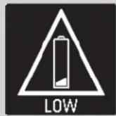
The disposable/rechargeable batteries are empty or used up if the recycling time (time from the triggering of a full-power flash, e.g. in the M mode, to the moment the flash-ready indicator lights up again) exceeds 60 seconds. In addition "LOW" appears in the touch display.
- Switch off the flash unit. To do this, press the ② button until all displays turn off.
- Remove the flash unit from the camera and slide down the battery compartment cover ⑩
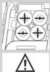
- Insert the batteries and slide the battery compartment cover ⑩ back up.
When inserting batteries, ensure that the polarity is correct and matches the symbols in the battery compartment. Inserting the batteries in the wrong direction can destroy the flash unit! Always replace all batteries simultaneously, and make sure that batteries are the same brand and have the same capacity. Flat or dead batteries should not be disposed of with ordinary household waste. Help protect the environment, and dispose of flat/dead batteries at the appropriate collection points!


3.3 Switching the flash unit on and off
- Switch on the flash unit with the ① ② button.
The start screen appears.
The flash unit always switches on
afterwards with the mode of operation that was used last (e.g. manual flash mode M).
The button flashes red in stand-by mode. To switch off the flash unit, press the ② button until all displays turn on
If the flash unit will not be used for an extended period of time, we recommend that you switch off the flash unit with the button and remove the power source (disposable/rechargeable batteries).
3.4 The selection menu
- Press the 7 button as often as it takes for the selection menu to appear.
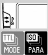
The selection menu is divided into 4 sensor buttons:
The modes of operation can be set after pressing the MODE.
TTL, see 7.1
TTL FP, see 7.4
M, see 7.3
MFP,see 7.4
SLAVE, see 10.2
SERVO,see 10.4
The flash parameters can be set after pressing the PARA
EV (exposure correction), see 8
Zoom(reflector setting), see 9.1
F (aperture)
ISO (light sensitivity),
P (partial light output),
see 7.3 and 10.4.3
CHANNEL3) (Channel), see 10.1.2, 10.2.2
GROUP3) (slave group), see 10.2.3.
3) only in SLAVE mode
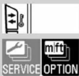
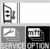
The touch display can be configured after pressing the SERVICE, or the flash unit can be reset to the factory setting.
CONTRAST see 14.1
BRIGHTNESS see 14.2
ROTATION (rotate the screen display), see 14.3
RESET, see 15.3
The options can be set after pressing the OPTION button.
ZOOM SIZE (shooting format adjustment), see 11.2.4
ZOOM MODE (illumination), see 11.2
STANDBY (autom., unit switch-off), see 3.6
MOD.LIGHT (modelling light), see 11.1 AF BEAM (AF auxiliary light), see 11.3 m / ft (metres / feet), see 11.5
In the menus shown on the flash unit, all fields that have a black background are configured as sensor buttons that can be pressed for modifications/changes in the menu.
In the images in the user's guide, only the sensor buttons that must be pressed for setting the described function are marked in black.
TTL
0.3-3,9m

INFO
—INFO
F>8,0
A.Zoom 35mm
ISO 100
EV +1 2/3
3.5 INFO
The current settings of the flash unit can be displayed during operation.
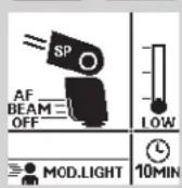
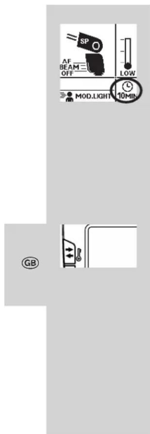
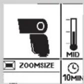
- Press the Info sensor button on the touch display. Info panel 1 appears.
- Spot zoom mode (SP) is set, (see 11.2.2).
- Shooting format adjustment (ZOOMSIZE) (see 11.2.4)
- AF-BEAM (AF auxiliary light) is switched off, (see 11.3).
- Modelling light (MOD.LIGHT) is set, (see 11.1).
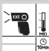
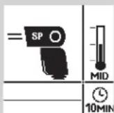
- The automatic unit switch-off is set for 10 minutes (see 3.6).
- The temperature display increases after intensive use.
- While info panel 1 is being displayed, press the touch display once again.
Info panel 2 will be displayed.
3.6 Auto OFF for the flash unit
The flash unit is factory-set to automatically switch to standby mode (Auto OFF) 10 minutes after -
-
being switched on,
-
a flash is fired,
- the shutter release is actuated,
- the camera's exposure metering system is switched off. ..
... switched to stand-by mode, (Auto-OFF) to save energy and to protect the power source from unintentional discharging. The active automatic unit switch-off is shown in the INFO display. The flash ready indicator 6 and the indicators on the LC display disappear.
The button flashes red in stand-by mode.
The most recently used operating setting is retained after automatic shutdown and is immediately restored when the camera is switched on.
The flash unit can be turned on again by pressing the 4 button, or by tapping on the shutter release (wake-up function).
In slave-/ servo mode, the automatic cut-off is not activated.
The flash unit should always be turned off using the main switch ② if it is not going to be used for an extended period!
If necessary, the Auto OFF function can be set to occur after 1 minute of inactivity, or can be deactivated.
The flash unit switches off completely about 1 hour after its last use.


SERVICE OPTION
ZOOM MODE
STANDBY
MOD.LIGHT


STANDBY
Off
1 min
10 min
Setting the automatic unit switch-off
- Switch on the flash unit with the ① button. The start screen appears. The flash unit always switches on afterwards with the mode of operation that was used last (e.g. manual flash mode M).
- Press the 4 button as often as it takes for the selection menu to appear.
- Press the OPTION button on the touch display.
- Press the 8s. 3 buttons on the touch display and select "STANDBY".
- Press the STANDBY button on the touch display.
- Tap the sensor button on the touch display for the desired time. The setting is adopted immediately. The operation display appears after about 10 seconds, or press the button repeatedly until the operation display appears.
The button flashes red in stand-by mode.


4 LED displays on the flash unit
4.1 Flash readiness indication
When the flash capacitor on the flash unit is charged, the 6 button lights up in green, thus indicating that the flash unit is ready. This means that flash light can be used for the next shot. Flash readiness is also transmitted to the camera and indicated accordingly in the camera's viewfinder. If a photograph is taken before flash readiness appears, then the flash unit will not be triggered. If the camera has already switched to flash sync speed, the shot may have the wrong exposure (see 13.1).
4.2 Correct exposure indication
If the exposure is correct, then button lights up in red for around 3 seconds if the photograph has been correctly exposed in flash modes TTL and TTL FP (see 7.1)! If there is no exposure control indication after the shot, then the photograph was underexposed. In that case, you must:
- set the next smaller f-stop (e.g. use f-stop 8 instead of 11), or
GB

- reduce the distance to the subject or to the reflection surface (e.g. for indirect flashes), or
- set a higher ISO value on the camera. Note the maximum flash range indicated on the display of the flash unit (see 5.2).
5 Information in Display
The Olympus cameras transmit the settings for ISO, lens focal length (mm) and aperture to the flash unit.
It calculates the maximum flash range from the settings and their guide number.
Flash mode, range, aperture and zoom position of the reflector are displayed in the display of the flash unit.
If the flash unit is operated without receiving data from the camera, then the values set on the flash unit will be shown.
Display illumination
After pressing the button on the flash unit, or after tapping the touch display, the display illumination will be activated for approximately 10 sec.
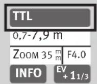

5.1 Display of the flash mode
The current flash mode is shown in the display. Depending on the type of camera, different displays are available for the selected TTL flash mode (e.g. TTL, TTL FP, see 7.1) and the manual flash mode M (see 7.3).
5.2 Range display
The flash range is displayed when using cameras that transmit ISO, lens focal length and aperture data. For this a data exchange must have occurred between the camera and flash unit, for example by tapping the shutter release. The range can be displayed either in metres (m) or feet (ft) - see 11.6).
The flash range is not displayed when . . .
- no data is transmitted from the camera.
- when the reflector head is tilted out of its normal position (upwards or sideways).
- The flash unit is working in SLAVE or SERVO mode.
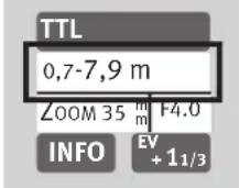
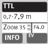
Range display in TTL and TTL FP flash modes
In the TTL flash modes TTL and TTL FP; see 7.1) the value for the minimum and the maximum range of the flash unit is displayed. The value indicated relates to subjects with a reflection factor of 25% which applies to most photographic situations.
Strong deviations from this reflection factor, as in the case of highly reflective or poorly reflective subjects, may affect the flash range of the flash unit.
The subject should be in the range of 40% to 70% of the maximum range. This will give the electronics sufficient scope for compensation.
To prevent overexposure, the minimum distance to the subject should not be undershot
Adjustment to the photographic situation at hand can be achieved by, for example, changing the aperture of the setting on the lens.
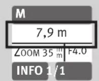
Range display in manual flash mode M
In manual flash mode, the distance that must be maintained from the subject for correct flash exposure is indicated.
Adjustment to the photographic situation at hand can be achieved by, for example, changing the aperture setting on the lens or selecting a manual partial light output level (see 7.3).
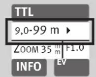
Exceeding the display range
Flash ranges of up to 99 m or 99 ft can be shown in the display.
This display range can be exceeded in the case of high ISO values and large aperture openings.
An arrow or triangle after the distance value indicates that the display range has been exceeded.
6 Displays in the camera viewfinder
Examples for the camera display:
Flash symbol flashes:
Prompt indicating that the flash unit is to be switched on or used (by some cameras).
Flash symbol is illuminated:
The flash unit is ready for use (by some cameras).
For information applicable to the displays in the viewfinder of your camera model, refer to the camera's operating instructions!
7 Flash modes
You can choose from the following operating modes:
-TTL
-TTLFP
-M
-MFP
- REMOTE-SLAVE
-M-SERVO
The flash mode is set using the touch display.
7.1 TTL-flash mode
These flash modes offer a very simple method of obtaining very good flash shots. Here, the exposure is measured by a sensor in the camera. It measures the light reflected by the subject through the lens (TTL = "Through The Lens").
If the shot was exposed correctly, the correct exposure indication will illuminate for about 3 seconds (see 4.2).
Please note whether there are limitations for your camera in terms of film sensitivity for TTL flash mode (for example, ISO 64 to ISO 1000; see camera's operating instructions)!
When taking a shot, an almost imperceptible measurement pre-flash is triggered by the camera prior to the actual exposure process.
Setting the mode of operation
- Switch on the flash unit with the button. The start screen appears. Thereafter, the flash unit always switches on with the mode of operation that was used last (e.g. M flash mode).
- Press the displayed mode of operation on the touch display as many times as it takes for the display for selecting the mode of operation to appear.
- Press the s buttons on the touch display and select the desired mode of operation.
- Press on the selected mode of operation that is highlighted in black. The setting is adopted immediately.
- Set a suitable mode of operation on the camera, e.g. P, Tv, Av, M etc.
- Tap the shutter release to transfer data between the flash unit and the camera.

7.2 Automatic TTL Fill-in flash mode
The automatic TTL fill-in flash mode is activated by most cameras when the automatic programme P is selected and by Vari or subject programmes during daylight (see camera operating manual). Fill-in flash mode overcomes troublesome shadows and produces a more balanced exposure between subject and background with centre-jour shots. The camera's computer-controlled metering system sets the most suitable combination of shutter speed, aperture and flash output.
Ensure that the contre-jour light source does not shine directly into the lens, as this will interfere with the camera's TTL metering system!
There is no setting or display for automatic TTL fill-in flash in the flash unit.
GB

7.3 Manual flash mode
In the manual flash mode M, the flash unit emits the full uncontrolled amount of light if no partial light output has been selected. The specific photographic situation can be taken into account by adjusting the aperture setting or by selecting a suitable manual partial light setting.
The setting area ranges from P 1/1 to P 1/128 in Mm mod display shows the distance at which the subject is correctly lit (see 5.2).
Setting the mode of operation
- Switch on the flash unit with the ① ② button. The start screen appears. Thereafter, the flash unit always switches on with the mode of operation that was used last (e.g. TTL flash mode).
-
Press the sensor button of the displayed mode of operation on the touch display as many times as it takes for the display for selecting the mode of operation to appear.
-
Press the 品 s. buttons on the touch display and select M
- Press the Mhsor button on the touch display.

7,9m
ZOOM 35 m F4.0
INFO 1/1

- Set a suitable mode of operation on the camera, e.g. M.
- Tap the shutter release to transfer data between the flash unit and the camera.
Various cameras support manual flash mode M only in the camera's M mode (manual). In other camera models, an error message appears in the display and the release is locked.
Manual partial light output levels
Partial light output can be set in manual flash mode M
Setting procedure
- Press the sensor button for partial light output on the touch display as many times as it takes for the partial light output display to appear.
- Press sensor buttons to touch display and set the desired partial light output to 1/1, 1/2, 1/8 or 1/128.
1/16
1/16 1/3
1/16 2/3


- Press the sensor button on the touch display for the selected partial light output.
The setting is immediately effective and automatically saved.
The distance display is adjusted to the partial light output automatically (see 5.2).
7.4 Automatic high-speed synchronisation (FP)
Various cameras support automatic high-speed synchronisation (see the camera's operating instructions). This flash mode makes it possible to use a flash unit even with shutter speeds that are faster than the flash sync speed.
Interesting results may by achieved in this mode when, for example, a wide open aperture (e.g., f/2.0) is used to limit the depth of field in portrait shots taken in very bright ambient light. The flash unit supports high-speed synchronisation in TTL and M flash modes.
For physical reasons, however, high-speed synchronisation significantly reduces the number and the maximum flash range!
Be sure to note, therefore, the flash range on the display of the flash unit. High-speed synchronisation is activated automatically if a shutter speed faster than the flash sync speed is set on the camera, whether
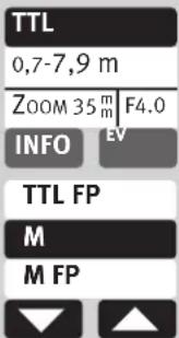
TTL
0,7-7,9 m
ZOOM35mF4.0
INFO
TTL
TTL FP
M


manually or automatically by the exposure program.
Note that in the case of high speed synchronisation the guide number of the flash unit also depends on the shutter speed.
The faster the shutter speed, the lower the guide number!
Setting the mode of operation
- Switch on the flash unit with the ① ② button. The start screen appears. Thereafter, the flash unit always switch on with the mode of operation that was used last (e.g. TTL flash mode).
- Tap the shutter release to transfer data between the flash unit and the camera.
- Press the sensor button of the displayed mode of operation on the touch display as many times as it takes for the display for selecting the mode of operation to appear.
- Press the s buttons on the touch display and select TTL FP
- Press the button on the touch display.
The setting will take effect immediately.
8 Manual flash exposure correction
The auto flash exposure mode of most cameras is adjusted to a reflection factor of 25% (the average reflection factor of flash subjects).
A dark background that absorbs much of the light or a highly reflective bright background (backlit shots, for example) may result in, respectively, underexposure or overexposure of the subject.
To offset these effects, the flash exposure can be adjusted manually for the shot with a correction value. The extent of the correction depends on the contrast between the subject and background!
In TTL flash modes, manual flash exposure correction factors of from -3 EV (f-stops) to +3 EV (f-stops) can be adjusted on the flash unit in one-third increments.
Tip:
Dark subject against light background: positive correction factor.
Light subject against dark background: negative correction factor.
Exposure correction by means of alteration of the lens aperture setting is impossible, since the camera's automatic exposure program regards the altered aperture setting as the normal working aperture setting. When setting the correction factor, the distance shown
TTL
0.7-7,9m
ZOOM 35 m F4.0
INFO
-1 1/3
-1
-2/3


TTL
0,7-7,9 m
ZOOM 35 m F4,0
INFO
EV -1
in the display can change and be adjusted to the correction factor (depending on the camera model)!
Setting procedure
-
Press the EV hsor buttons on the touch display as many times as it takes for the partial light output selection to appear.
-
Press the s buttons on the touch display and set a correction value.
- Press the selected correction value on the touch display, e.g.
The setting will take effect immediately.
Manual flash exposure correction is only possible in TTL flash mode if the camera supports this function (consult the camera's operating instructions)!
If the camera does not support this function, the adjusted correction will have no effect.
For some camera models, the manual flash exposure corrections must be adjusted on the camera. If this is the case, no correction value will appear on the flash unit display.

After the shot, remember to cancel the TTL flash exposure correction in the camera!
Strongly reflecting objects in the motif can have a negative impact on the camera's automatic exposure. The photograph will be underexposed. Remove reflecting objects or set a positive correction value.
9 Special functions
Depending on the camera model various special functions are available.
For this purpose, data exchange must first occur between the flash unit and camera to access and set the special functions, for example by tapping the shutter release.
The setting must occur immediately after accessing the special functions since otherwise the flash unit automatically switches back to normal flash operation after a few seconds!
9.1 Motor zoom reflector (.,Zoom")
The motor zoom reflector of the flash unit can illuminate lens angles from 24mm (35 mm format).
Thanks to the use of the integrated wide-angle diffuser (9), the illumination widens to 12mm .
Auto zoom.
The zoom position of the reflector is automatically adjusted to the lens focal length when the flash unit is used with a camera that transmits the data related to the lens focal length. After the flash unit has been switched on, „Zoom“ and the current zoom position of the reflector are shown in the display.
Automatic adjustment occurs for lens focal lengths from 24mm
The automatic adjustment will not be activated if the reflector is swivelled, if the wide-angle diffuser 9 is pulled out, or a Mecabounce (accessory) is mounted. If so desired, the position of the reflector can be manually adjusted in order to achieve particular lighting effects (such as spot effect etc.).
Manual zoom mode
The zoom position of the reflector must be adjusted manually to the lens focal length when used with a camera that doesn't transmit the data related to the lens focal length.
In this case auto-zoom mode is not possible!
After switching on the flash unit, „Zoom“ appears in the display and the current zoom position of the reflector appears.

ISO
MODE
PARA
EV
DM


50
70
13/14
85


Setting procedure
- Press the button as often as it takes for the selection menu to appear.
- Press the PARA button on the touch display.
- Press the Yes按钮 on the touch display and select "Zoom".
- Press the Zoom button on the touch display.
- Press the s buttons on the touch display and select the desired zoom value.
After around 10 seconds, the operation display appears, or press the button repeatedly until the operation display appears. The following zoom positions are possible for the reflector: 24 - 28 - 35 - 50 - 70 - 85 - 105 mm (35 mm format).
Tip:
If you do not necessarily need the full guide number and maximum flash range of the flash unit, you can leave the zoom reflector at the position for the shortest focal length of the zoom lens.
This will provide full light coverage of the picture and eliminate the need to continually adjust it to the focal length of the lens.
EV

ZOOM


A.Zoom
24

Example :
You use a zoom lens with a focal length range of 35mm to 105mm . In this case, you set the position of the reflector of the flash unit to 35mm .
Resetting to auto-zoom
- Touch the shutter release to begin a data transfer between the flash unit and the camera.
- Press the button as often as it takes for the selection menu to appear.
- Press the PARA button on the touch display.
- Press the s. buttons on the touch display and select "Zoom".
- Press the Zoom button on the touch display.
Press the 4sor buttons on the touch display and select A.Zoom
After around 10 seconds, the operation display appears, or press the button repeatedly until the operation display appears.
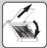

Wide-angle diffuser
With the wide angle diffuser 9, focal lengths of 12mm or more can be illuminated (35 mm format).
Pull the wide-angle diffuser ⑨ out from the reflector as far as it will go, and then release it.
The wide-angle diffuser 9 automatically folds downwards. The reflector automatically moves to the required position.
The distance readings and the zoom value are corrected to 12mm on the display panel.
The automatic adjustment of the motor-zoom reflector ⑨ is not activated if the wide-angle diffuser is in use.
To insert the wide-angle diffuser ⑨, turn it upwards 90^ and push it all the way in.
mecabounce Diffuser MBM-02
If the Mecabounce (optional accessories, see 18) is fitted to the reflector of the flash unit, the reflector is automatically guided to the position required. The distance data and zoom factor are corrected to 16mm .
The automatic adjustment of the motor-zoom reflector is not activated if the Mecabounce is in use.
The simultaneous use of the wide-angle diffuser and the Mecabounce is not possible.

10 Cordless flash mode
The flash unit is compatible as a slave flash unit with the wireless Olympus RC flash system (RC=remote control or remote mode).
The remote system consists of a master flash unit on the camera and one or more slave flash units. The slave flash unit(s) are controlled via wireless technology by the reflector of the master flash unit.
The slave flash unit is assigned to one of three possible groups (A, B or C). Each group can in turn consists of one or more slave flash units.
The entire remote system can be operated either with TTL mode or M mode.
There are four independent remote channels to use so that multiple remote systems in the same room do not interfere with one another. Master and Slave flash units belonging to the same remote system must be set to the same remote channel.
The slave flash units must be able to receive the light from the master flash unit with the integrated sensor for remote mode.
In remote flash mode, the maximum flash range is not indicated on the flash unit's display panel.

ZOOM 35 mm

10.1 Remote master mode settings
RC mode is in general set on the camera. If the master flash unit is deactivated, it only controls the slave units and does not contribute to exposing the shot!
10.1.1 Remote master mode settings
- Switch on the flash unit with the button. The start screen appears.
- Set RC mode on the camera.
Remote master mode is shown in the picture.
10.1.2 Remote channel settings
There are four independent remote channels to use so that multiple remote systems in the same room do not interfere with one another. Master and Slave flash units belonging to the same remote system must be set to the same remote channel.
The RC mode must be set on the camera and is transmitted to the flash units involved after a test flash.
10.2 Remote slave flash mode
The flash unit supports Olympus's wireless E TTL Remote System in slave flash mode.
At the same time, one or more slave flash units can be remotely controlled from one master flash unit on the camera (e.g. mecablitz 52 AF-1 O digital).
A slave flash unit can be assigned to one of three possible slave groups (GROUP A, B or C). The master flash unit can control all of these slave groups simultaneously and at the same time take the settings for each slave group into account.
So that multiple remote systems in the same room do not interfere with one another, there are four independent remote channels available (CH 1, 2, 3 or 4).
Master and slave flash units belonging to the same remote system must be set to the same remote channel.
The slave flash units must be able to receive the light from the master flash unit with the integrated sensors for the remote mode.
Depending on the camera model, the camera's internal flash unit can also function as master flash unit. Please consult the respective camera operating instructions for further tips on setting the master flash unit.
TTL
0.7-7,9m
ZOOM 35 m F4.0
INFO
MFP
SLAVE
SERVO

REMOTE SLAVE

CH A1
ZOOM 35 mm
INFO
10.2.1 Remote slave flash mode settings
- Switch on the flash unit with the ① button. The start screen appears. Thereafter, the flash unit always switches on with the mode of operation that was used last (e.g. M flash mode).
-
Press the displayed mode of operation on the touch display as many times as it takes for the display for selecting the mode of operation to appear.
-
Press the v s u buttons on the touch display and select "SLAVE".
- Press the SLAVE button on the touch display.
Remote slave mode is set.
In addition, the selected slave group (e.g. A) and the remote channel (e.g. CH 1) are displayed.
GB
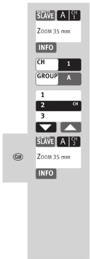
10.2.2 Setting the slave channel
- Press the sensor button on the touch display for the channel group (e.g. A TCH1) The window for selecting the channel and group appears.
- Press the sensor buttons on the touch display for the channel "CH".
- Press the s. buttons on the touch display and select the desired channel.
- Press the selected channel on the touch display.
The setting will take effect immediately.
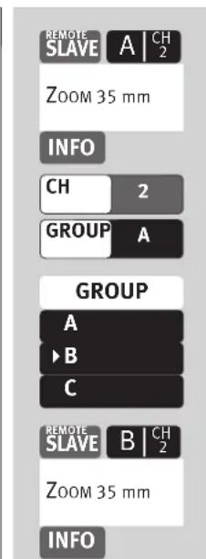
10.2.3 Setting the slave group
- Press the sensor button on the touch display for the channel group (e.g. A ICH2). The window for selecting the channel and group appears.
- Press the sensor button on the touch display for the group "GROUP".
- Press the sensor button on the touch display for the desired group "A", "B" or "C".
The setting will take effect immediately.
10.3 Testing remote flash mode
- Place the slave flash units in the desired positions for the shot. Use flash unit mounting foot S60 to set up the slave flash unit.
- Wait until the slave flash unit and the camera's controller flash unit are ready. Once the slave flash unit is ready, its AF measuring beam.
Take a test shot and check whether the slave flash unit(s) respond. - If the slave flash unit does not flash, correct the position of the slave flash unit so that it can receive the light from the controller flash unit or reduce the distance between the controller flash unit and the slave flash unit.
- Following the successful completion of the flash test, you can start taking shots.


10.4 SERVO mode
SERVO mode is a simple slave mode without or with complete pre-flash suppression in which the slave flash unit always triggers a flash as soon as the camera flash unit receives a light pulse.
In SERVO mode, only manual flash mode is possible. Manual flash mode is automatically activated after switching to SERVO mode.
10.4.1 Setting SERVO flash mode
- Set the camera to TTL mode.
-
Press the sensor button of the displayed mode of operation on the touch display as many times as it takes for the display for selecting the mode of operation to appear.
-
Press the 8-s 7-t按钮 on the touch display and select „SERVO".
- Press the SERY0 button on the touch display.
The mode of operation is adopted. If desired, partial light output can be set, see 10.4.3.
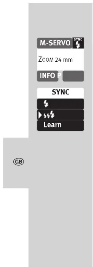
10.4.2 Pre-flash suppression or synchronisation settings
- Set the camera to TTL mode.
-
Press the sensor button SYNC e touch display as many times as it takes for the display for selecting the type of synchronisation.
-
Press the sensor button on the touch display: synchronisation without pre-flash synchronisation with pre-flash The mode of operation is adopted
If the synchronisation set here does not work properly, then proceed as described in 10.4.4.
M-SERVO
ZOOM 24 mm
INFO

1/1
1/1 1/3


1/8 -²/3
1/16
1/16 -1/3


M-SERVO
ZOOM 35 mm
INFO
16
10.4.3 Servo mode partial light output settings
- Press the sensor button P partial light output on the touch display as many times as it takes for the partial light output display to appear.
- Press sensor buttons
touch display and set the desired partial light output to 1/1, 1/2, 1/8 or 1/128.
- Press the sensor button on the touch display for the selected partial light output (e.g. 1/16 1/16).
The partial light output is adopted.
Once the slave flash units have achieved flash-readiness, the AF measurement flash flashes.
Slave groups and remote channels cannot be set in SERVO mode.
The camera flash unit may not work in the remote mode
10.4.4 Learn function
The "Learn function" enables individual automatic adjustment of the slave flash unit to the flash technology of the camera's flash unit.
In the process, one or more pre-flashes, e.g. to reduce the "red-eye effect" of the camera flash unit can be taken into account. The slave flash unit is then fired to coincide with the main flash that illuminates the actual picture.
If the camera's own flash device provides for automatic focussing AF measuring flashes, then due to the system characteristics no learn operation is possible. If possible, use another camera mode or change to manual focussing.
M-SERVO
Zoom 24 mm
INFO

SYNC


Learn
Learning Mode

Take Picture
Setting procedure for the learn function
The AF pre-flash function of the camera must be switched off.
-
Press the SYNC or buttons on the touch display as many times as it takes for the selection to appear.
-
Press the Learn or button on the touch display.
-
"Learning Mode" is ready to learn.
- Press the release button on the camera so that the camera's own flash unit is activated. If the SERVO flash unit has received a light pulse, then "LEARN OK" appears in the display as confirmation.
The macablitz 52 AF-1 digital has learned the flash of the camera flash unit.
M-SERV0
ZOOM 24 mm
INFO:16
SLAVE
SERVO

TTL

10.4.5 Switching-off SERVO flash mode
- Press the displayed mode of operation on the touch display as many times as it takes for the display for selecting the mode of operation to appear.
- Press the s. buttons on the touch display and select the desired mode of operation, e.g. TTL
- Press the sensor button on the touch display for the mode of operation, e.g.
The selected mode of operation is adopted.
STANDBY
MOD.LIGHT
AF BEAM

MOD.LIGHT
Off

12 =
11 OPTION menu
11.1 Modelling light
The modelling light is a high-frequency stroboscopic flash. It creates the impression of a semi-permanent light for a duration of about 3 seconds. The modelling light enables the user to assess light distribution and the formation of shadows before taking pictures.
The modelling light is triggered with the manual firing button 6.
Setting procedure
- Press the 2 button as often as it takes for the selection menu to appear.
- Press the OPTION button on the touch display.
- Press the s buttons on the touch display and select "MOD.LIGHT".
- Press the MOD. Lightton on the touch display.
- Press the ON button on the touch display and switch the modelling light on or off. The setting is adopted immediately.
After activation of the modelling light, "MOD.LIGHT" appears in the INFO menu.
11.2 Zoom Mode
11.2.1 Extended Zoom Mode
In extended zoom mode the zoom position of the reflector is reduced to one level below the focal length of the camera lens.
The resulting expanded and broader light coverage provides additional dispersed light (reflections) inside rooms so that a softer flash illumination is possible.
Example :
The focal length of the camera lens is 50~mm . The extended zoom mode sets a 35~mm reflector position on the flash unit. However, 50~mm continues to be shown on the display.
Setting procedure
- Press the button as often as it takes for the selection menu to appear.
- Press the OPTION button on the touch display.
- Press the 6s 1 buttons on the touch display and select „ZOOM MODE".
- Press the zoom mode often as it takes for the selection menu to appear.
ZOOM MODE
EXTENDED
STANDARD
SPOT
- Press the EXTENDED button on the touch display.
The setting is adopted immediately.
After activation of extended zoom mode, "EXT" appears in the INFO menu.
Depending on the system, the extended zoom mode is supported for lens focal lengths of 28mm or more (35-mm format). The camera must be equipped with a CPU lens and be able to transfer data on the lens focal length to the flash unit.
11.2.2 SPOT zoom mode
In spot zoom mode, the zoom position of the reflector is increased by one level compared to the focal length of the camera lens. The resulting reduced illumination provides centre-weighted illumination or alternatively shadowy edge lighting.
Example :
The focal length of the camera lens is 50mm . The spot zoom mode sets a 70~mm reflector position on the flash unit. However, 50~mm continues to be shown on the display.
ZOOM SIZE
ZOOM MODE
STANDBY

ZOOM MODE
EXTENDED
STANDARD
SPOT
Setting procedure
- Press the 12 button as often as it takes for the selection menu to appear.
-
Press the OPTION button on the touch display.
-
Press the 按钮ons on the touch display and select "ZOOM MODE".
-
Press the ZOOM MODE button on the touch display.
-
Press the SPOT button on the touch display.
The setting is adopted immediately.
After activation of spot zoom mode, "SP" appears in the INFO menu.
Depending on the system, the spot zoom mode is supported for lens focal lengths to 85mm or more (35-mm format).
The camera must be equipped with a CPU lens and be able to transfer data on the lens focal length to the flash unit.


SERVICE OPTION
ZOOM SIZE
ZOOM MODE
STANDBY


ZOOM MODE
EXTENDED
STANDARD
SPOT
11.2.3 STANDARD zoom mode
In standard zoom mode, the zoom position of the reflector is adjusted to the focal length of the camera lens.
Setting procedure
- Press the button as often as it takes for the selection menu to appear.
- Press the OPTION button on the touch display.
- Press the 0s 1 buttons on the touch display and select "ZOOM MODE".
-
Press the ZOOM MODEtton on the touch display.
-
Press the STANDARD button on the touch display.
The setting is adopted immediately.


ZOOM SIZE
ZOOM MODE


ZOOM SIZE

11.2.4 Shooting format adjustment (Zoom-Size)
Certain types of digital cameras allow the display for the position of the reflector to be adjusted to chip-format (dimensions of the recording module) using the Zoom Size function.
Setting procedure
- Press the button as often as it takes for the selection menu to appear.
- Press the OPTION button on the touch display.
- Press the s. buttons on the touch display and select "ZOOM SIZE".
- Press the ZOOM SIZE button on the touch display.
- Press the ON or button on the touch display. The setting is adopted immediately.
"ZOOM SIZE" appears in the INFO menu after activation of the zoom size function.
The Zoom Size function cannot be set with cameras which do not support shooting format adjustment!
11.3 AF-BEAM (AF auxiliary light)
If the AF metering system of a digital AF reflex camera is unable to focus due to insufficient ambient lighting, the camera activates the AF auxiliary light ⑬ built into the flash unit. This projects a stripe pattern onto the subject which the camera uses to focus.
With the "AF-BEAM" function, the AF auxiliary light can be switched on or off.
The range is approx. 6m 9m with a standard 1.7 / 50~mm lens). Parallax error between the lens and AF auxiliary light ③ limits the close-up range with the AF auxiliary light to approximately 0.7m to 1m
If the automatic AF auxiliary light ⑬ is to be activated by the camera, the "Single-AF (S)" autofocus mode must be set on the camera and the flash unit must indicate flash readiness.
Some camera models support only the camera's internal AF auxiliary light. In this case, the automatic AF auxiliary light of the flash unit is not activated (as in the case of compact cameras; see the camera's operating instructions)!
Low-speed zoom lenses can significantly curtail the range of the AF auxiliary light!
Some cameras support the AF auxiliary light in the flash unit only with the camera's central AF sensor 13. If a peripheral AF sensor 13 is selected, then the AF auxiliary light will not be activated in the flash unit!!
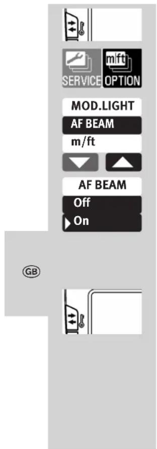
Setting procedure
- Press the button as often as it takes for the selection menu to appear.
- Press the OPTION button on the touch display.
- Press the 8s. 10tions on the touch display and select "AF BEAM".
- Press the AF BEAM button on the touch display.
- Press the On Gen button on the touch display.
The setting is adopted immediately.
11.4 Locking / unlocking
The setting on the flash unit can be locked against unintended changes.
To lock or unlock, hold down the button for approximately 3 seconds.
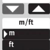
11.5 Range display in m or ft
The range indication in the display can either be shown in metres (m) or feet (ft).
be shown in metre Setting procedure
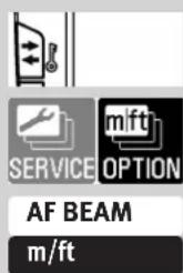
- Press the 7 button as often as it takes for the selection menu to appear.
- Press the OPTION button on the touch display.
- Press the s buttons on the touch display and select "m/ft".
-
Press the m/ft r button on the touch display.
-
Press the m sel fbr button on the touch display.
The setting is adopted immediately.
12 Flash techniques
12.1 Bounce flash
Bounce flash illuminates the subject more softly and reduces dense shadows. It also reduces the drop in light from foreground to background that occurs for physical reasons.
The reflector of the flash unit can be swivelled horizontally and tilted vertically for bounce flash.
To avoid colour cast in your shots, the reflective surface should be colour-neutral or white.
When tilting the reflector vertically, make sure that it is turned through an angle that is wide enough to prevent direct light from falling on the subject. For this reason the reflector should be tilted at least as far as the 60^ lock-in position. When the reflector head is tilted, the reflector is moved to a position of 70mm in order to prevent the subject from being additionally illuminated by dispersed light.
The range and position of the reflector is not displayed.
12.2 Bounce flash with a reflector card
The use of bounce flash with the integrated reflector card ⑧ can bring out highlights in the eyes of human subjects:
- Tilt the reflector head upwards by 90^ .
- Pull the reflector card together with the wide-angle diffuser from above out of the reflector head and forwards.
- Hold the reflector card ⑧ and push the wide-angle diffuser ⑨ back into the reflector head.
13 Flash synchronisation
13.1 Automatic flash sync speed control
Depending on the camera model and camera mode, the shutter speed is switched to flash sync speed when flash readiness is reached (see the camera's operating instructions).
Shutter speeds cannot be set faster than the flash sync speed, or they are switched automatically to the flash sync speed.
Various cameras have a sync speed range, for example from 1/60 sec to 1/250 sec (see the camera's operating instructions). The sync speed set by the camera depends on the camera mode, the ambient light, and the focal length of the lens used.
Shutter speeds slower than the flash sync speed can be set according to the camera mode and the selected flash synchronisation.
If a camera with a between-the-lens shutter and high-speed synchronisation (see 7.4) is used, flash sync speed is not controlled automatically. As a result, the flash can be used at all shutter speeds. If you need the full light output of the flash unit, you should not select a shutter speed that is any faster than 1/125 sec.
13.2 Normal synchronisation
In normal synchronisation the flash unit is triggered at the beginning of the shutter time (first curtain synchronisation). Normal synchronisation is the standard mode on all cameras. It is suitable for most flash shots. The camera, depending on the mode being used, is switched to the flash sync speed. Speeds between 1/30 sec. and 1/125 sec. are customary (see the camera's operating instructions).
No settings are necessary on the flash unit, nor is there any display for this mode.
13.3 Slow synchronisation (SLOW)
A slow exposure (SLOW) gives added prominence to the image background at lower ambient light levels. This is achieved by adjusting the shutter speed to the ambient light. Accordingly, shutter speeds that are slower than the flash sync speed (e.g., shutter speeds up to 30 sec.) are automatically adjusted by the camera. Slow synchronisation is activated automatically on some camera models in connection with certain camera programs (e.g., a night shot program, etc.), or it can be set on the camera (see the camera's operating instructions). No settings are necessary on the flash unit, nor is there any display for this mode.
No settings are necessary on the flash unit, nor is there any display for this mode!
Slow synchronisation SLOW is set on the camera (see camera's operating instructions)! Use a tripod when shooting with slow shutter speeds to avoid blurred images!
13.4 Second curtain synchronisation (REAR)
Some cameras offer the option of second-curtain synchronisation (REAR), in which the flash unit is not triggered until the end of the exposure time.
This is particularly advantageous when used with lower shutter speeds (slower than 1/30 sec.) and moving subjects that have their own source of light. With second-curtain synchronisation, a moving light source will trail a light streak instead of building one up ahead itself, as it does when the flash is synchronised with the first shutter curtain. In this way a „more natural“ image of the photographic situation is produced!
Depending on its operating mode, the camera sets shutter speeds slower than its sync speed.
The REAR mode is set on the camera (see camera's operating instructions).
There is no display for REAR mode in the flash unit.
CONTRAST
BRIGHTNESS

CONTRAST
High
Middle
Low
14 Touch display settings
14.1 Contrast
The screen contrast can be changed in three levels.
Setting procedure
- Press the 12 button as often as it takes for the selection menu to appear.
- Press the SERVICE button on the touch display.
- Press the s buttons on the touch display and select "CONTRAST".
- Press the CONTRAST button on the touch display.
- Press the following sensor buttons on the touch display
High for high contrast.
Middle for medium contrast.
LOW for low contrast.
The setting is adopted immediately.


SERVICE OPTION
BRIGHTNESS
ROTATION


CONTRAST
High
Middle
Low
14.2 Brightness
The screen brightness can be changed in three levels.
Setting procedure
- Press the button as often as it takes for the selection menu to appear.
- Press the SERVICE button on the touch display.
- Press the s buttons on the touch display and select "BRIGHTNESS".
- Press the BRIGHTNESS button on the touch display.
- Press the following sensor buttons on the touch display
High for maximum brightness.
Middle for medium brightness.
Low for low brightness.
The setting is adopted immediately.
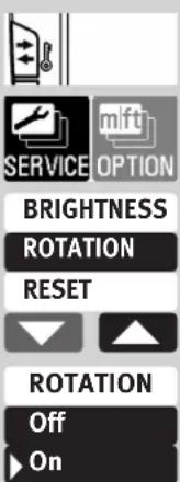
14.3 Rotation
When the flash unit is rotated in the horizontal direction, the screen display can also be rotated.
Setting procedure
- Press the button as often as it takes for the selection menu to appear.
- Press the SERVICE button on the touch display.
- Press the 串 buttons on the touch display and select "RATATION".
- Press the ROTATION button on the touch display.
- Press the ON or button on the touch display.
The setting is adopted immediately.
GB
15 Care and maintenance
Remove dust and grime with a soft dry cloth or silicon-treated cloth.
Do not use cleaning agents as these may damage the plastic parts.
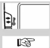
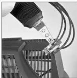
15.1 Firmware-Update
The firmware version (V.10 in the example) of the flash unit is shown in the start screen after switching on.
The flash unit's firmware can be updated through the USB port (1) and adjusted to the technical requirements of future cameras (Firmware Update).
For more information, visit the Metz homepage at www.metz.de
15.2 Conditioning the flash capacitor
The flash capacitor built into the flash unit undergoes a physical change when the device has not been used for a long time. For this reason it is necessary to switch the device every three months for approx. 10 mins. The power supplies must deliver enough power so that flash standby lights up no later than 1 min after switching on.

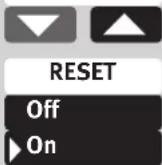
15.3 Reset
The flash unit can be reset to the factory settings when delivered.
Setting procedure
-
Press the button as often as it takes for the selection menu to appear.
-
Press the SERVICE button on the touch display.
-
Press the s buttons on the touch display and select "RESET".
-
Press the RST button on the touch display.
-
Press the ON or button on the touch display. All settings are adopted immediately and the flash unit is reset to its factory settings.
This will not affect the firmware updates for the flash unit!
16 Troubleshooting
Should the flash unit fail to function properly or meaningless content appear on the flash unit display panel, switch the flash unit off with the main switch 2 for approximately 10 seconds. Check the camera settings and make sure the foot of the flash unit is mounted correctly in the camera's accessory shoe.
Replace the batteries with new or freshly charged batteries!
The flash unit should function normally again once it is switched back on. If this is not the case, contact your local dealer.
Below is a list of some of the problems that may occur when the flash unit is used.
For each item, possible causes and remedies for the problem are listed.
No maximum flash range indication appears on the display panel.
- There has been no exchange of data between the flash unit and the camera.
Tap the camera's shutter release.
The reflector is not in normal position.
The AF measuring beam of the flash unit is not activated.
The flash unit is not ready for firing.
The camera is not in „Single-AF (S" mode.
- The camera supports only its own internal AF measuring beam.
- Some cameras support the AF measuring beam in the flash unit only with the camera's central AF sensor. If a peripheral AF sensor is selected, then the AF measuring beam will not be activated in the flash unit.
Activate the central AF sensor.
The "AF BEAM" is switched off. Switch on "AF BEAM", see 11.4.
The reflector position is not automatically adjusted to the current zoom position of the lens.
The camera does not transfer data to the flash unit
- There is no exchange of data between the flash unit and the camera.
Tap the camera's shutter release.
- The camera is equipped with a lens without CPU.
The flash unit operates in manual zoom mode, MZoom". Switch to Auto-Zoom (see 11.2.3).
The reflector is swivelled out of its locked normal position.
The wide-angle diffuser folds out from the reflector.
- A Mecabounce is mounted in front of the reflector.
The aperture setting on the flash unit is not automatically adjusted to that of the lens.
The camera does not transfer data to the flash unit
- There is no exchange of data between the flash unit and the camera.
Tap the camera's shutter release.
- The camera is equipped with a lens without CPU.
The indicator for the zoom position of the reflector is blinking on display panel
- Warning of shadowing on the edge of the image: the focal length set on the camera lens (converted to the 35mm format, 24x36) is shorter than the adjusted zoom position of the reflector.
The setting for manual TTL flash exposure correction has no effect.
The camera does not support manual TTL flash exposure correction on the flash unit.
Automatic switching to the flash sync speed fails to occur.
- The camera has a between-the-lens shutter (as do most compact cameras), Switching to sync speed is therefore unnecessary.
- The camera operates with high-speed synchronisation FP (camera settings). Switching to sync speed does not occur in the process.
- The camera operates with shutter speeds that are slower than the flash sync speed. Depending on the camera mode, there is no switch to flash sync speed (see the camera's operating instructions).
The shots are too dark.
The subject is beyond the range of the flash unit.
Note: Using bounce flash reduces the range of the flash unit.
- The subject contains very bright or highly reflective areas. The metering system of the camera or flash unit is deceived as a result.
Set a positive manual flash exposure correction, e.g., +1 EV.
The shots are too bright.
- In close-up shots, overexposure (shots that are too bright) may result if the shutter speed is faster than the flash sync speed.
The minimum distance from the subject should be at least 10% of the maximum flash range indicated on the display.
The aperture (f-stop) cannot be adjusted on the flash unit.
- There is an exchange of digital data between the flash unit and camera.
Adjustment of the aperture is not possible!
17 Technical data
Max. guide numbers at ISO 100/21°, zoom 105 mm:
In the metric system: 52
In the imperial system: 170
Flash modes:
TTL, Manuel M, Automatic high-speed synchronisation TTL FP, M FP, Remote slave mode, servo flash mode.
Manual partial light output levels:
P1/1... P1/ 128 in one-third increments.
P1/1... P1/64 light output, in automatic high-speed synchronisation (FP)
Flash durations: see table 2, page (Page 256)
Colour temperature: Ca. 5600 K
Sensitivity to light: ISO 6 to ISO 51200
Synchronisation:

low-voltage ignition
Number of flashes: see table 3, page (Page 257)
Recycling time: see table 3, page (Page 257)
Light coverage:
Reflector from 24 mm (35 mm format)
Reflector with wide-angle diffuser from 12mm (35 mm format).
Swivelling ranges and locking positions of the reflector:
upwards: 45^ 60^ 75^ 90^
counter-clockwise:
60^90^120^150^180^
clockwise:
60^90^120^
Dimensions, approx., in mm (W x H x D):
ca. 73 × 134 × 90
Weight :
Flash unit without batteries approx. 346g
Included:
Flash unit with integrated wide-angle diffuser, operating instructions, Flash unit mounting foot S60, Belt pouch T58.
18 Optional accessories
We accept no liability for malfunctions of or damage to the flash unit caused by the use of accessories of other manufacturers!
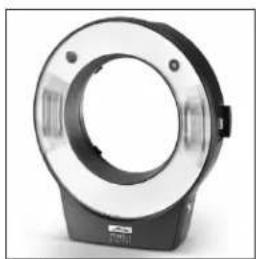
- mecabounce Diffuser MBM-02
(Order No. 000001908)
With this diffuser, soft lighting can be achieved in a very simple manner.
It gives your pictures a marvellous soft appearance. Skin tones are captured more faithfully.
The maximum working range is reduced by about half in conformity with the loss of light.
- Bounce diffuser 58-23
(Order No. 000058235)
Softens heavy shadows with reflected light.
- Flash unit mounting foot S60
(Order No. 000000607)
Flash unit mounting foot for slave mode.

Disposal of batteries
Do not dispose of spent batteries with domestic rubbish.
Please return spent batteries to collecting points should they exist in your country!
Please return only fully discharged batteries.
Normally, batteries are fully discharged if:
-
the device they powered switches itself off and indicates "Spent Batteries".
-
they no longer function properly after prolonged use.
To ensure short-circuit safety please cover the battery poles with adhesive tape.
Errors excepted. Subject to changes!
Premessa 173
14.2 Brightness (Brillo)
(N ^2 ref. 000001908)
Table 1: Guide numbers at maximum light output (P 1/1)
Your Metz product was developed and manufactured with high-quality materials and components which can be recycled and/or re-used.

This symbol indicates that electrical and electronic equipment must be disposed of separately from normal gar-bage at the end of its operational lifetime.
Please dispose of this product by bringing it to your local collection point or recycling centre for such equipment.
This will help to protect the environment in which we all live.

Within the framework of the CE approval symbol, correct exposure was evaluated in the course of the electromagnetic compatibility test.
Do not touch the SCA contacts! In exceptional cases the unit can be damaged if these contacts are touched.

Atencion:

Errors excepted. Subject to changes!
Consumer electronics Photoelectronics Plastics technology
711470057.A2
Metz - always first class.

C
D F
NL GB
(1)
E