CJ 110VA - Saw HITACHI - Free user manual and instructions
Find the device manual for free CJ 110VA HITACHI in PDF.
User questions about CJ 110VA HITACHI
0 question about this device. Answer the ones you know or ask your own.
Ask a new question about this device
Download the instructions for your Saw in PDF format for free! Find your manual CJ 110VA - HITACHI and take your electronic device back in hand. On this page are published all the documents necessary for the use of your device. CJ 110VA by HITACHI.
USER MANUAL CJ 110VA HITACHI
INSTRUCTION MANUAL AND SAFETY INSTRUCTIONS
WARNING
Improper and unsafe use of this power tool can result in death or serious bodily injury!
This manual contains important information about product safety. Please read and understand this manual before operating the power tool. Please keep this manual available for others before they use the power tool.
MODE D'EMPLOI ET INSTRUCTIONS DE SECURITE
AVERTISSEMENT
MEANINGS OF SIGNAL WORDS .... 3
SAFETY
IMPORTANT SAFETY INSTRUCTIONS
FOR USING ALL POWER TOOLS 4
IMPORTANT SAFETY INSTRUCTIONS
FOR USE OF THE DEMOLITION HAMMER ... 7
REPLACEMENT PARTS 7
POLARIZED PLUGS 7
USE OF EXTENSION CORD 8
SERVICE AND REPAIRS 17
TABLE DES MATIERES
Français
Page
INFORMATIONS IMPORTANTES .... 19
SIGNIFICATION DES MOTS D'AVERTISSEMENT .. 19
SECURITE
CONSIGNES DE SECURITE IMPORTANTES POUR
L'UTILISATION DE TOUS LES OUTILS ELECTRIQUES... 20
CONSIGNES DE SECURITE IMPORTANTES
POUR L'UTILISATION DU SCIE SAUTEUSE 24
PIECES DE RECHANGE 24
FICHE POLARISEES 24
CORDON DE RALLONGE 25
DOUBLE ISOLATION POUR UN
FONCTIONNEMENT PLUS SUR 26
Page
UTILISATION ET ENTRETIEN
NOM DES PIECES 27
SPECIFICATIONS 27
ACCESSIONES 28
ACCESSIONS STANDARD 28
ACCESSOIRESN OPTION 28
APPLICATIONS 28
Read and understand all of the operating instructions, safety precautions and warnings in the Instruction Manual before operating or maintaining this power tool.
Most accidents that result from power tool operation and maintenance are caused by the failure to observe basic safety rules or precautions. An accident can often be avoided by recognizing a potentially hazardous situation before it occurs, and by observing appropriate safety procedures.
Basic safety precautions are outlined in the "SAFETY" section of this Instruction Manual and in the sections which contain the operation and maintenance instructions.
Hazards that must be avoided to prevent bodily injury or machine damage are identified by WARNINGS on the power tool and in this Instruction Manual.
Never use this power tool in a manner that has not been specifically recommended by HITACHI, unless you first confirm that the planned use will be safe for you and others.
MEANINGS OF SIGNAL WORDS
WARNING indicates a potentially hazardous situations which, if ignored, could result in serious personal injury.
CAUTION indicates a hazardous situations which, if ignored, could result in moderate personal injury, or could cause machine damage.
NOTE emphasizes essential information.
SAFETY
IMPORTANT SAFETY INSTRUCTIONS FOR USING ALL POWER TOOLS
WARNING: Death or serious bodily injury could result from improper or unsafe use of power tools. To avoid these risks, follow these basic safety instructions:
READ ALL INSTRUCTIONS
Never place your hands, fingers or other body parts near the tool's moving parts.
2. NEVER OPERATE WITHOUT ALL GUARDS IN PLACE.
Never operate this tool without all guards or safety features in place and in proper working order. If maintenance or servicing requires the removal of a guard or safety feature, be sure to replace the guard or safety feature before resuming operation of the tool.
3. ALWAYS WEAR EYE AND EAR PROTECTOR.
Protect yourself from flying or expelled wood chips, metal particles or other debris by using protective goggles or equivalent eye protector. Wear ear protector to protect yourself from excessive noise.
4. PROTECT YOURSELF AGAINST ELECTRIC SHOCK.
Prevent body contact with grounded surfaces such as pipes, radiators, ranges and refrigeration enclosures. Never operate the tool in damp or wet locations.
5.DISCONNECT TOOLS.
Never leave the tool connected to a power source. Always disconnect the tool from its power source before servicing, inspecting, maintaining, cleaning and before changing or checking any parts.
6. AVOID UNINTENTIONAL STARTING.
Don't carry the tool while it is connected to its power source. Don't carry the tool with your finger near the power switch. Be sure the power switch is in the "off" position before connecting the tool to its power source.
7. STORE TOOL PROPERLY.
When not in use, the tool should be stored in a dry place. Keep out of reach of children. Lock-out the storage area.
8. KEEP WORK AREA CLEAN.
Cluttered areas and benches invite injuries. Clear all work areas and work benches of unnecessary tools, debris, furniture, etc.
9. CONSIDER WORK AREA ENVIRONMENT.
Don't expose power tools to rain. Don't use power tools in damp or wet locations. Keep work area well lit and well ventilated.
Don't use tool in presence of flammable liquids or gases.
Power tools produce sparks during operation. They also spark when switching ON/OFF. Never use power tools in sites containing lacquer, paint, benzine, thinner, gasoline, gases, adhesive agents, and other materials which are combustible or explosive.
10. KEEP CHILDREN AWAY.
Do not let visitors contact tool or extension cord.
All visitors should be kept safely away from work area.
11. DON'T FORCE TOOL.
It will do the job better and safer at the rate for which it was intended.
12. USE RIGHT TOOL.
Don't force small tool or attachment to do the job of a heavy-duty tool.
Don't use tool for purpose not intended—for example—don't use circular saw for cutting tree limbs or logs.
13. DRESS PROPERLY.
Do not wear loose clothing or jewelry. They can be caught in moving parts.
Rubber gloves and non-skid footwear are recommended when working outdoors.
Wear protective hair covering to contain long hair.
14. USE FACE, DUST MASK OR RESPIRATOR IF OPERATION IS DUSTY.
All persons in the area where power tools are being operated should also wear face, dust mask or respirator.
15. DON'T ABUSE CORD.
Never carry tool by cord or yank it to disconnect from receptacle.
Keep cord from heat, oil and sharp edges.
16. SECURE WORK.
Use clamps or a vise to hold work. It's safer than using your hand and it frees both hands to operate tool.
17. DON'T OVERREACH.
Keep proper footing and balance at all times.
18. MAINTAIN TOOLS WITH CARE.
Keep tools sharp and clean for better and safer performance.
Follow instructions for lubricating and changing accessories.
Inspect tool cords periodically and if damaged, have repaired by an authorized service center. Inspect extension cords periodically and replace if damaged.
Keep handles dry, clean, and free from oil and grease.
19. REMOVE ADJUSTING KEYS AND WRENCHES.
Keys and adjusting wrenches remove from tool before turning it on.
20. OUTDOOR USE EXTENSION CORD.
When tool is used outdoors, use only extension cord intended for use outdoors and so marked.
21. STAY ALERT.
Watch what you are doing. Use common sense. Do not operate tool when you are tired.
Tools should never be used by you if you are under the influence of alcohol, drugs or medication that makes you drowsy.
22. CHECK DAMAGED PARTS.
Before further use of the tool, a guard or other part that is damaged should be carefully checked to determine that it will operate properly and perform its intended function. Check for alignment of moving parts, binding of moving parts, breakage of parts, mounting, and any other conditions that may affect its operation.
A guard or other part that is damaged should be properly repaired or replaced by an authorized service center unless otherwise indicated elsewhere in this Instruction Manual.
Have defective switches replaced by the authorized service center.
Do not use tool if switch does not turn it on and off.
- NEVER USE A POWER TOOL FOR APPLICATIONS OTHER THAN THOSE SPECIFIED.
Never use a power tool for applications other than those specified in the Instruction Manual.
- HANDLE TOOL CORRECTLY.
Operate the tool according to the instructions provided herein. Do not drop or throw the tool. Never allow the tool to be operated by children, individuals unfamiliar with its operation or unauthorized personnel.
- CHECK FOR LIVE WIRES.
Avoid the risk of severe electrical shock by checking for live electrical wires that may be buried in walls, floors or ceilings. The wires should be de-energized before work begins.
- KEEP ALL SCREWS, BOLTS AND COVERS TIGHTLY IN PLACE.
Keep all screws, bolts, and plates tightly mounted. Check their condition periodically.
- DO NOT USE POWER TOOLS IF THE PLASTIC HOUSING OR HANDLE IS CRACKED.
Cracks in the tool's housing or handle can lead to electric shock. Such tools should not be used until repaired.
- BLADES AND ACCESSORIES MUST BE SECURELY MOUNTED TO THE TOOL.
Prevent potential injuries to yourself or others. Blades, cutting implements and accessories which have been mounted to the tool should be secure and tight.
- KEEP MOTOR AIR VENT CLEAN.
The tool's motor air vent must be kept clean so that air can freely flow at all times. Check for dust build-up frequently.
- OPERATE POWER TOOLS AT THE RATED VOLTAGE.
Operate the power tool at voltages specified on its nameplate.
If using the power tool at a higher voltage than the rated voltage, it will result in abnormally fast motor revolution and may damage the unit and the motor may burn out.
- NEVER USE A TOOL WHICH IS DEFECTIVE OR OPERATING ABNORMALLY.
If the tool appears to be operating unusually, making strange noises, or otherwise appears defective, stop using it immediately and arrange for repairs by a Hitachi authorized service center.
Don't leave tool until it comes to a complete stop.
- CAREFULLY HANDLE POWER TOOLS.
Should a power tool be dropped or struck against hard materials inadvertently, it may be deformed, cracked, or damaged.
- DO NOT WIPE PLASTIC PARTS WITH SOLVENT.
Solvents such as gasoline, thinner benzine, carbon tetrachloride, and alcohol may damage and crack plastic parts. Do not wipe them with such solvents.
Wipe plastic parts with a soft cloth lightly dampened with soapy water and dry thoroughly.
- USE ONLY Genuine HITACHI REPLACEMENT PARTS.
Replacement parts not manufactured by Hitachi may void your warranty and can lead to malfunction and resulting injuries. Genuine Hitachi parts are available from your dealer.
IMPORTANT SAFETY INSTRUCTIONS FOR USE OF THE JIG SAW
WARNING: Death or serious bodily injury could result from improper or unsafe use of the jig saw. To avoid these risks, follow these basic safety instructions:
This machine employs a high-power motor. If the machine is used continuously at low speed, an extra load is applied to the motor which can result in motor seizure. Always operate the power tool so that the blade is not caught by the workpiece during operation. Always adjust the blade speed to enable smooth cutting.
REPLACEMENT PARTS
When servicing use only identical replacement parts.
Repairs should be conducted only by a Hitachi authorized service center.
POLARIZED PLUGS
To reduce the risk of electric shock, this equipment has a polarized plug (one blade is wider than the other).
This plug will fit in a polarized outlet only one way.
If the plug does not fit fully in the outlet, reverse the plug.
If it still does not fit, contact a qualified electrician to install the proper outlet.
Do not change the plug in any way.
USE OF EXTENSION CORD
Make sure your extension cord is in good condition. When using an extension cord, be sure to use one heavy enough to carry the current your product will draw. An undersized cord will cause a drop in line voltage resulting in loss of power and overheating. Table shows the correct size to use depending on cord length and nameplate ampere rating. If in doubt, use the next heavier gage. The smaller the gage number, the heavier the cord.
MINIMUM GAGE FOR CORD SETS
| Total Length of Cord in Feet (Meter) | |||||
| 0 - 25(0 - 7.6) | 26 - 50(7.9 - 15.2) | 51 - 100(15.5 - 30.5) | 101 - 150(30.8 - 45.7) | ||
| Ampere Rating AWG More Not More Than Than | |||||
| 0 - 6 | 1 | 8 | 1 | 6 | 1 |
| 6 - 10 18 16 14 12 | |||||
| 10 - 12 | 16 16 14 12 | ||||
| 12 - 16 | 14 | 12 | Not Recommended | ||

WARNING: Avoid electrical shock hazard. Never use this tool with a damaged or frayed electrical cord or extension cord.
Inspect all electrical cords regularly. Never use in or near water or in any environment where electric shock is possible.
To ensure safer operation of this power tool, HITACHI has adopted a double insulation design. "Double insulation" means that two physically separated insulation systems have been used to insulate the electrically conductive materials connected to the power supply from the outer frame handled by the operator. Therefore, either the symbol "回" or the words and "Double insulation" appear on the power tool or on the nameplate.
Although this system has no external grounding, you must still follow the normal electrical safety precautions given in this Instruction Manual, including not using the power tool in wet environments.
To keep the double insulation system effective, follow these precautions:
- Only HITACHI AUTHORIZATIONED SERVICE CENTER should disassemble or assemble this power tool, and only genuine HITACHI replacement parts should be installed.
Clean the exterior of the power tool only with a soft cloth moistened with soapy water, and dry thoroughly.
Never use solvents, gasoline or thinners on plastic components; otherwise the plastic may dissolve.
SAVE THESE INSTRUCTIONS AND MAKE THEM AVAILABLE TO OTHER USERS OF THIS TOOL!
The information contained in this Instruction Manual is designed to assist you in the safe operation and maintenance of the power tool.
Some illustrations in this Instruction Manual may show details or attachments that differ from those on your own power tool
NAME OF PARTS
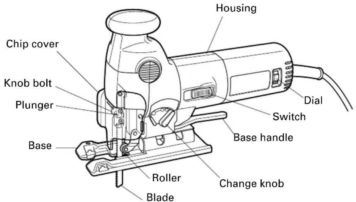
Fig. 1
SPECIFICATIONS
| Motor Single-Phase, Series Commutator Motor | |
| Power Source Single-Phase, 115V AC 60Hz | |
| Capacity Wood 4-1/4" (110mm) | Mind steel 3/8" (10mm) |
| Current 5.2A | |
| No-load speed 700 ~ 3200 spm | |
| Stroke 1" (26mm) | |
| Min. cutting radius 1" (25mm) | |
| Weight 5.3 lbs (2.4 kg) | |
ACCESSIONS
WARNING: Accessories for this power tool are mentioned in this Instruction Manual. The use of any other attachment or accessory can be dangerous and could cause injury or mechanical damage.
STANDARD ACCESSORIES
No. 41 Blade
No. 42 Blade
No. 46 Blade
Splinter guard (Code No. 306363) 1
OPTIONAL ACCESSORIES ...... sold separately
1 Blade (Long) (Code No. 879227)
.95 Blade (Code No. 950482)
.11 Blade (Code No. 963390)
.96 Blade (Code No. 950480)
.12 Blade (Code No.963391)
.97 Blade (Code No. 963400)
.15 Blade (Code No.963392)
Dust collector
.16 Blade (Code No.963393)
Rectilinear guide (Code No. 305955)
.21 Blade (Code No. 963394)
Circular guide (Code No. 305956)
.22 Blade (Code No. 963395)
Bench stand (Model TR12-B)
NOTE:
Accessories are subject to change without any obligation on the part of the HITACHI.
APPLICATIONS
Cutting various lumber and pocket cutting
Cutting mild steel plate, aluminum plate, and copper plate
Cutting plastics, such as phenol resin and vinyl chloride
Cutting thin and soft construction materials
Cutting stainless steel plate (With No. 95, No. 96 or No. 97 blade)
PRIOR TO OPERATION
1. Power source
Ensure that the power source to be utilized conforms to the power source requirements specified on the product nameplate.
2. Power switch
Ensure that the switch is in the OFF position. If the plug is connected to a receptacle while the switch is in the ON position, the power tool will start operating immediately and can cause serious injury.
3. Extension cord
When the work area is far away from the power source, use an extension cord of sufficient thickness and rated capacity. The extension cord should be kept as short as practicable.
WARNING: Damaged cord must be replaced or repaired.
4. Check the receptacle
If the receptacle only loosely accepts the plug, the receptacle must be repaired. Contact a licensed electrician to make appropriate repairs.
If such a faultly receptacle is used, it may cause overheating, resulting in a serious hazard.
5. Confirming condition of the environment:
Confirm that the work site is placed under appropriate conditions conforming to prescribed precautions.
6. Mounting the blade
(1) Open the chip cover. (Fig. 2)
(2) Fully loosen the knob screw at the end of the plunger (Fig. 3).
(3) Fully insert the blade mount into the ring with the back of the blade in the roller slot and the blade edge facing forward, then firmly tighten the knob screw (Fig. 3, 4).
(4) Close the chip cover. (Fig. 2)
NOTES:
O Blade damage can result if the knob screw is loose; therefore, tighten it firmly. Also, any chips from cutting that enter between the knob screw, washer and set piece, or into the blade mount of the set ring can result in improper blade mounting. Use caution.
Periodically lubricate by using spindle oil between the rotating parts of the rollers, washers and set pieces, and on the threads of the knob screw.
- Adjusting the blade operating speed The jig saw is equipped with the electric control circuit which enables stepless speed control. To adjust the speed, turn the dial shown in Fig. 5. When the dial is set to "1", the jig saw operates at the minimum speed (700/min.). When the dial set to "5", the jig saw operates at the maximum speed (3200/min.). Adjust the speed according to the material to be cut and working efficiency.
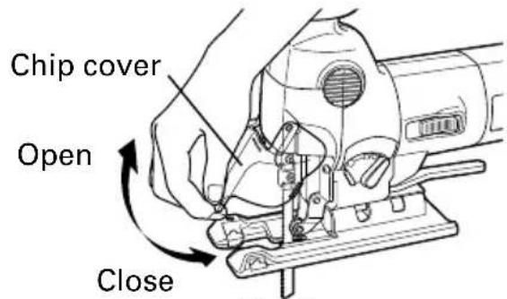
Fig. 2
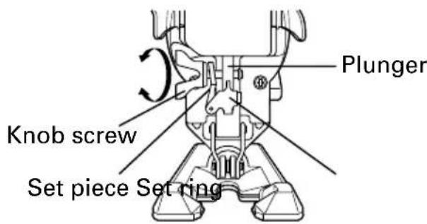
Fig. 3
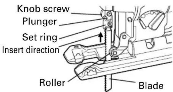
Fig. 4
CAUTION
-
At low speed (dial setting: 1 or 2) do not cut a wood with a thickness of more than 3/8'' (10 mm) or metal with a thickness of more than 1/32'' (1 mm).
-
Adjusting the orbital operation
(1) This machine employs orbital operation which moves the blade back and forth, as well as up and down. Set the change knob shown in Fig. 6 to "0" to eliminate the orbital operation (the blade moves only up and down). The orbital operation can be selected in 4 steps from "0" to "III".
(2) For the hard material, such as a steel plate, etc., decrease the orbital operation. For the soft material, such as lumber, plastic, etc., increase the orbital operation to increase work efficiency. To cut the material accurately, decrease the orbital operation.
- Cutting stainless steel plates
The jig saw model, when used with the No. 95, No. 96 or No. 97 blade, can cut stainless steel plates. Carefully read "Concerning cutting of stainless steel plates" for proper operation.
10.Splinter guard
Using the splinter guard when cutting wood materials will reduce splintering of cut surfaces.
Insert the splinter guard in the space between the base and sub-base (A), push forward and attach (see Fig. 7).
CUTTING
CAUTIONS
While sawing, the base must be firmly in contact with the material surface, and the blade must be held at a right angle. If the base becomes separated from the material, it could cause the blade to break.
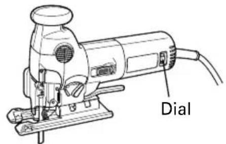
Fig. 5
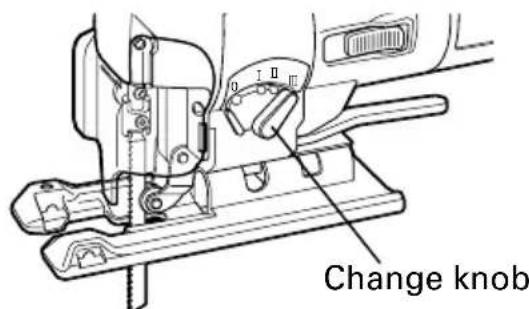
Fig. 6
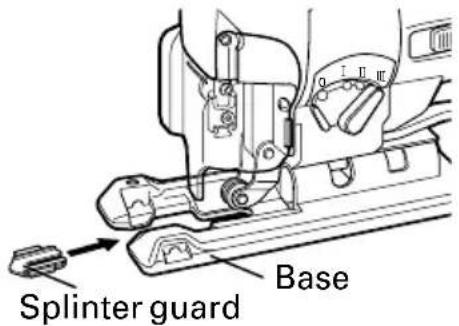
Fig. 7
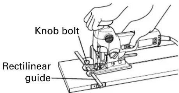
Fig. 8
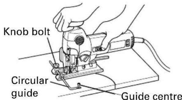
Fig. 9
1. Rectilinear cutting
When cutting on a straight line, first draw a marking gauge line and advance the saw along that line. Using the auxiliary straight guide (sold separately) will make it possible to cut accurately on a straight line. Attach the guide by passing it through the attachment hole on the base and tightening the M5 knob bolt. (Fig. 8)
2. Sawing curved lines
When sawing a small circular arc, reduce the feeding speed of the machine. If the machine is fed too fast, it could cause the blade to break.
3. Cutting a circle or a circular arc
In this case it will be helpful to use the auxiliary circular guide and guide center (sold separately) (Fig. 9).
Loosen the base handle located directly below the housing by rotating it approximately 90 degrees. Then move the base fully forward, rotate base handle approximately 90 degrees counterclockwise, return the base to directly below the housing and tighten (Figs. 10, 11).
Pass the circular guide through the attachment hold on the base and tighten the M5 knob bolt.
4. Cutting metallic materials
Always use an appropriate cutting agent (spindle oil, soapy water, etc.) When a liquid cutting agent is not available, apply grease to the back surface of the material to be cut.
5. Pocket cutting
(1) In lumber
Aligning the blade direction with the grain of the wood, cut step by step until a window hole is cut in the center of the lumber. (Fig. 12)
(2) In other materials
When cutting a window hole in materials other than lumber, initially bore a hole with a drill or similar tool from which to start cutting.
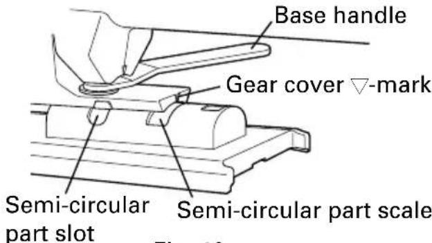
Fig. 10
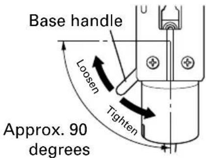
Fig. 11
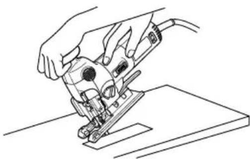
Fig. 12
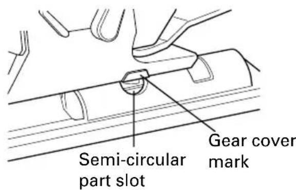
Fig. 13
6. Angular cutting
To adjust the slant angle, loosen the base handle located directly below the housing by rotating it approximately 90 degrees and then move the groove in the semicircular part to the position indicated by the mark on the gear cover.
Next, align the scale (from 0 degrees to 45 degrees in 15-degree increments) of the semi-circular part of the base with the [V] mark on the gear cover, rotate the base handle approximately 90 degrees counterclockwise, return to directly below the housing and tighten (Figs. 10, 11, 13, 14).
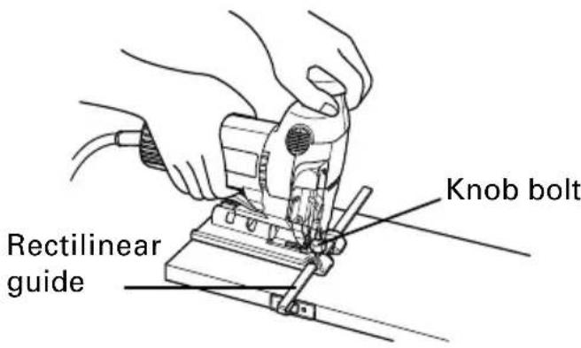
Fig. 14
CONCERNING CUTTING OF STAINLESS STEEL PLATES
When used with the No. 95, No. 96 or No. 97 blade, can cut stainless steel plates. Note the following to adjust the unit
CAUTION
While sawing, the base must be firmly in contact with the workpiece surface, and the blade must be held at a right angle. If the base becomes separated from the material, it could cause the blade to break.
When cutting stainless steel plates, adjust the unit as described below:
- Adjust the speed.....
| Blade Thickness of material Dial Scale | |
| No. 96 1/64" ~ 1/16" (0.5 mm ~ 1.5 mm) | Middle groove position between scales “2” and “3” |
| No. 95 1/16" ~ 5/32" (1.5 mm ~ 2.5 mm) | |
| No. 97 1/16" ~ 5/32" (1.5 mm ~ 2.5 mm) |
NOTE
Dial scale reading is for reference only. The higher the speed is, the quicker the material is cut. But the service life of the blade will be reduced in this case. When the speed is too low, cutting will take longer, although the service life will be prolonged. Make adjustments as desired.
- Set the orbital position to "0"
NOTE
When cutting use cutting fluid (oil base cutting fluid) to prolong the blade's service life.
SELECTION OF BLADES
Accessory blades
To ensure maximum operating efficiency and results, it is very important to select the appropriate blade best suited to the type and thickness of the material to be cut. Three types of blades are provided as standard accessories. The blade number is engraved in the vicinity of the mounting portion of each blade. Select appropriate blades by referring to Table 1 (page 18).
MAINTENANCE AND INSPECTION
WARNING: Be sure to switch power OFF and disconnect the plug from the receptacle during maintenance and inspection.
- Inspecting the blade
Continued use of a dull or damaged blade will result in reduced cutting efficiency and may cause overloading of the motor. Replace the blade with a new one as soon as excessive abrasion is noted.
- Inspecting the mounting screws
Regularly inspect all mounting screws and ensure that they are properly tightened. Should any of the screws be loosened, retighten them immediately.
WARNING: Using this jig saw with loosened screws is extremely dangerous.
- Inspecting the carbon brushes (Fig. 15)
The motor employs carbon brushes which are consumable parts. Replace the carbon brushes with new ones when it becomes worn to its wear limit. When an auto-stop carbon brush is equipped, the motor will stop automatically. At that time, replace both carbon brushes with new ones. Always keep carabon brushes clean and ensure that they slide freely within the brush holders.
CAUTION
Using this jig saw with a carbon brush which is worn in excess of the wear limit will damage the motor
NOTE: Use HITACHI carbon brush No. 46 indicated in Fig. 15.
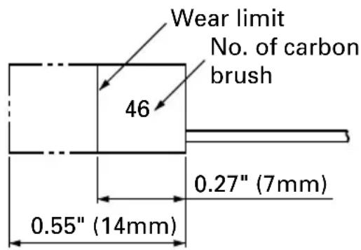
Fig. 15
4. Replacing carbon brushes (Fig. 16)
(1) Loosen the D4 tapping screw (1 screw) retaining the tail cover and remove the tail cover.
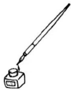
(2) Use a small screwdriver to pull up the edge of the spiral springs that are holding down the carbon brushes. Remove toward the outside of the brush holders.
(3) Remove the edge of the pig-tails on the carbon brushes, from the wiring block group (A) and then remove the carbon brushes from the brush holders.
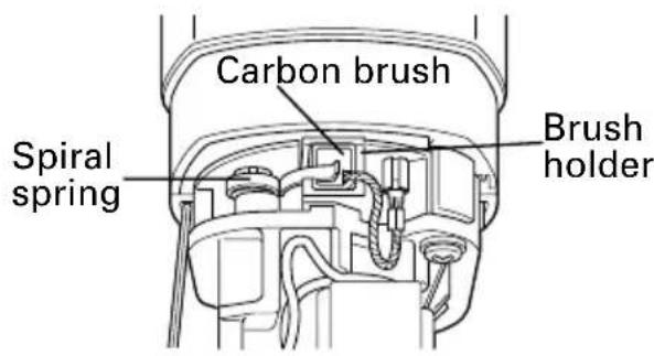
Fig. 16
(1) Insert the end of the pig tails of the carbon brushes in the terminal section of the wiring block (A).
(2) Insert the carbon brushes in the brush holders.
(3) Use the small screwdriver to return the edge of the spiral spring to the head of the carbon brushes.
(4) Check that the pig tail of the carbon brushes are completely inserted in the pig tail groove on the brush holders.
(5) Close the tail cover and tighten the D4 tapping screw (1 screw).
SERVICE AND REPAIRS
All quality power tools will eventually require servicing or replacement of parts because of wear from normal use. To assure that only authorized replacement parts will be used, all service and repairs must be performed by a HITACHI AUTHORIZATION SERVICE CENTER, ONLY.
NOTE:
Specifications are subject to change without any obligation on the part of the HITACHI.
Table 1 List of appropriate blades
| Material to be cut | Blade Material quality | No. 1 (Long) | No. 11 | No. 12,42 | No. 15 | No. 16,46 | No. 21,41 No. 22 No. 95 | No. 96 No. 97 | ||
| Thickness of material: inch (mm) | ||||||||||
| Lumber | General lumber | Below 3/8 4-1/4 (110) | ~2-1/2 Below 3/8 (10~65) 3/4 (20) (10) | ~2-1/2 3 ~65) (5 | 16 ~1-9/16 ~40) | |||||
| Plywood | 3/16~1-3/16 (5~30) 3/8 | Below 3/16 (10) (5) | ~1-3/16 ~30) | 1/8 ~3/4 (3~20) | ||||||
| Iron plate | Mild steel plate | 1/8~3/8 Below 1/8(3) (3) | 1/8 ~1/4 Below 1/6) | low 5/64 1/8(3) | ~3/16 (2~5) | |||||
| Stainless steel plate | 1/16~5/32 (1.5~2.5) | 1/16~5/32 (1.5~2.5) | ||||||||
| Nonferrous metal | Aluminium copper, brass | 1/8~15/32 (3~12) Below 1/8(3) (3) | 1/8~15/32 ~12) | Below Below 1/8(3) 3/16(5) | ||||||
| Aluminium sash | Height up to 1-3/8(35) | Height up to 1-3/8(35) | Height up to 1-3/8(35) | |||||||
| Plastics | Phenol resin, melamin resin, etc. | 3/16~3/4 (5~20) Below 1/4(6) | 3/16~19/32 (5~15) | Below 1/4(6) | 3/16~3/4 (5~20) | Below 1/4(6) | 3/16~19/32 (5~15) | |||
| Vinyl chloride, acryl resin, etc. | 3/16~1-3/16 (5~30) | Below 3/8(10) | 3/16~3/4 (5~20) Below 3/16(5) | 3/16~1-3/16 (5~30) (3 | 1/8 ~3/4 ~20) | 3/16~3/4 (5~20) | Below 3/16(5) (5 | 3/16~19/32 ~15) | ||
| Foamed polyethyl-ene, foamed styrol | 3/8~2-1/2 (10~65) (3 | 1/8~1-3/16 ~30) | 3/16~1-1/2 (5~40) | 1/8~1-3/16 (3~30) (10 | 3/8~2-1/2 ~65) (3 | 1/8~1-1/2 (5~40) | 1/8 ~1-3/16 (3~30) (5 | 3/16 ~1-3/8 ~35) | ||
| Pulp | Card board, corrugated paper | 3/8~2-1/2 (10~65) (3 | 1/8~1-3/16 ~30) | 3/8~2-1/2 (10~65) (3 | 1/8~1-1/2 ~40) | |||||
| Hardboard | 1/8~1-3/16 (3~30) Below 1/4(6) | 1/8 | ~1-3/16 (3~30) | Below 1/8 1/4(6) | ~1-3/16 (3~30) | |||||
| Fiberboard | Below 1/4(6) | |||||||||
NOTE
The minimum cutting radius of No. 1 (Long), No. 21, No. 22 and No. 41 blades is 3 - 15 / 16'' (100 mm).
No. 1 (Long), No. 11, No. 12, No. 15, No. 16, No. 21, No. 22, No. 95, No. 96 and No. 97 blades are sold separately.
INFORMATIONS IMPORTANTES
No. 1 Lame (Long) (No. de code 879227)
No. 11 Lame (No. de code 963390)
No. 12 Lame (No. de code 963391)
No. 15 Lame (No. de code 963392)
No. 16 Lame (No. de code 963393)
No. 21 Lame (No. de code 963394)
No. 22 Lame (No. de code 963395)
No.95 Lame (No.de code 950482)
REMARQUE
Le rayon de coupe minimal des Iames No. 1 (Long), No. 21, No. 22 et No. 41 est de 100~mm
Les Iames No. 1(Long), No. 11, No. 12, No. 15, No. 16, No. 21, No. 22, No. 95, No. 96 et No. 97 sont vendues séparément.
INFORMACION IMPORTANTE
2. Serrar lines as curvas
Cuchillas accessories
NOTA
El radio minimo de corte de las cucillas, No. 1 (Largo), No. 21, No. 22 y No. 41 es de 100mm
Las cuchillas No. 1 (Largo), No. 11, No. 12, No. 15, No. 16, No. 21, No. 22, No. 95, No. 96 y No. 97 se venden separamente.
Hitachi Koki Co., Ltd.
Nippon Bldg., 6-2, Ohtemachi 2-chome, Chiyoda-ku, Tokyo 100-0004, Japan