
CJ160V - Saw HITACHI - Free user manual and instructions
Find the device manual for free CJ160V HITACHI in PDF.

| Product Type | Jigsaw |
| Brand | Hitachi |
| Model | CJ160V / CJ160VA |
| Power Supply | 120 V, 60 Hz, single phase |
| Rated Current | 7.0 A |
| No-load speed | 800 - 2,800 /min |
| Stroke | 26 mm (1-1/32 in) |
| Cutting capacity (wood) | 160 mm (6-19/64 in) |
| Cutting capacity (aluminum) | 20 mm (25/32 in) |
| Cutting capacity (mild steel) | 10 mm (25/64 in) |
| Min. cutting radius | 25 mm (1 in) |
| Weight | 2.5 kg (5.5 lb) |
| Double insulation | Yes (symbol ☐) |
| Speed adjustment | 5-position dial (1-5) + AUTO mode |
| Orbital action | 4 positions (0 to III) |
| Anti-splinter | Yes, included |
| Auxiliary base | Yes, included |
| LED light | Yes, integrated |
| Vacuum connection | Possible via included adapter |
| Blades supplied | No. 41, No. 42, No. 123X |
| Maintenance | Regular blade inspection and replacement, screw inspection, exterior cleaning |
| Repairability | Genuine Hitachi parts, authorized after-sales service only |
| Optional accessories | Blades No. 1, 11, 12, 15, 16, 21, 22, 31, 97; cutting guide |
Frequently Asked Questions - CJ160V HITACHI
User questions about CJ160V HITACHI
0 question about this device. Answer the ones you know or ask your own.
Ask a new question about this device
Download the instructions for your Saw in PDF format for free! Find your manual CJ160V - HITACHI and take your electronic device back in hand. On this page are published all the documents necessary for the use of your device. CJ160V by HITACHI.
USER MANUAL CJ160V HITACHI
natural_image
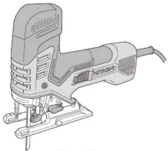
Line drawing of a Nitrogen Jigsaw tool with screw base (no text or symbols)CJ160V
natural_image
Line drawing of a JF50 electric shaver with screw base (no text or symbols)CJ160VA
SAFETY INSTRUCTIONS AND INSTRUCTION MANUAL
! WARNING
IMPROPER OR UNSAFE use of this power tool can result in death or serious bodily injury! This manual contains important information about product safety. Please read and understand this manual BEFORE operating the power tool. Please keep this manual available for other users and owners before they use the power tool. This manual should be stored in safe place.
INSTRUCTIONS DE SECURITE ET MODE D'EMPLOI
! AVERTISSEMENT
IMPORTANT SAFETY INSTRUCTIONS ......3
MEANINGS OF SIGNAL WORDS ....3
SAFETY....3
GENERAL POWER TOOL SAFETY WARNINGS ....3
SPECIFIC SAFETY RULES AND SYMBOLS .....5
ASSEMBLY AND OPERATION....8
APPLICATIONS......8
CONNECTING WITH CLEANER 15
MAINTENANCE AND INSPECTION....16
ACCESSORIES 18
STANDARD ACCESSORIES ....18
OPTIONAL ACCESSORIES (sold separately) ....18
PARTS LIST....54
TABLE DES MATIÈRES
Français
Page Page
CONSIGNES DE SÉCURITÉ IMPORTANTES ...19
SIGNIFICATION DES MOTS D'AVERTISSEMENT....19
SÉCURITÉ ......19
AVERTISSEMENTS DE SÉCURITÉ GÉNÉRAUX CONCERNANT LES OUTILS ÉLECTRIQUES ......19
REGLES DE SECURITE SPECIFIQUES ET SYMBOLES ....21
DOUBLE ISOLATION POUR UN FONCTIONNEMENT PLUS SUR......22
UTILISATION D'UN CORDON DE RALLONGE....23
DESCRIPTION FONCTIONNELLE ......24
NOM DES PARTIES 24
SPECIFICATIONS 24
ASSEMBLAGE ET FONCTIONNEMENT....25
APPLICATIONS....25
AVANT L'UTILISATION ....25
COUPE 30
AU SUJET DU DECOUPAGE DE PLAQUES EN ACIER INOXYDABLE ....32
CHOIX DES LAMES ....32
RANGEMENT DE LA CLÉ ALLEN 32
RACCORDEMENT AU NETTOYEUR ....32
ENTRETIEN ET INSPECTION ....33
ACCESSOIRES 35
ACCESSOIRES STANDARD ....35
IMPORTANT SAFETY INSTRUCTIONS
Read and understand all of the safety precautions, warnings and operating instructions in the instruction manual before operating or maintaining this power tool.
Most accidents that result from power tool operation and maintenance are caused by the failure to observe basic safety rules or precautions. An accident can often be avoided by recognizing a potentially hazardous situation before it occurs, and by observing appropriate safety procedures.
Basic safety precautions are outlined in the “SAFETY” section of this instruction manual and in the sections which contain the operation and maintenance instructions.
Hazards that must be avoided to prevent bodily injury or machine damage are identified by WARNINGS on the power tool and in this instruction manual.
Never use this power tool in a manner that has not been specifically recommended by HITACHI.
MEANINGS OF SIGNAL WORDS
WARNING indicates a potentially hazardous situations which, if ignored, could result in death or serious injury.
CAUTION indicates a potentially hazardous situations which, if not avoided, may result in minor or moderate injury, or may cause machine damage.
NOTE emphasizes essential information.
SAFETY
GENERAL POWER TOOL SAFETY WARNINGS
WARNING
Read all safety warnings and all instructions.
Failure to follow the warnings and instructions may result in electric shock, fire and/or serious injury.
Save all warnings and instructions for future reference.
The term “power tool” in the warnings refers to your mains-operated (corded) power tool or battery-operated (cordless) power tool.
1) Work area safety
a) Keep work area clean and well lit.
Cluttered or dark areas invite accidents.
b) Do not operate power tools in explosive atmospheres, such as in the presence of flammable liquids, gases or dust.
Power tools create sparks which may ignite the dust or fumes.
c) Keep children and bystanders away while operating a power tool.
Distractions can cause you to lose control.
2) Electrical safety
a) Power tool plugs must match the outlet.
Never modify the plug in any way.
Do not use any adapter plugs with earthed (grounded) power tools.
Unmodified plugs and matching outlets will reduce risk of electric shock.
b) Avoid body contact with earthed or grounded surfaces such as pipes, radiators, ranges and refrigerators.
There is an increased risk of electric shock if your body is earthed or grounded.
c) Do not expose power tools to rain or wet conditions.
Water entering a power tool will increase the risk of electric shock.
d) Do not abuse the cord. Never use the cord for carrying, pulling or unplugging the power tool.
Keep cord away from heat, oil, sharp edges or moving parts.
Damaged or entangled cords increase the risk of electric shock.
e) When operating a power tool outdoors, use an extension cord suitable for outdoor use.
Use of a cord suitable for outdoor use reduces the risk of electric shock.
f) If operating a power tool in a damp location is unavoidable, use a residual current device (RCD) protected supply.
Use of an RCD reduces the risk of electric shock.
3) Personal safety
a) Stay alert, watch what you are doing and use common sense when operating a power tool.
Do not use a power tool while you are tired or under the influence of drugs, alcohol or medication.
A moment of inattention while operating power tools may result in serious personal injury.
b) Use personal protective equipment. Always wear eye protection.
Protective equipment such as dust mask, non-skid safety shoes, hard hat, or hearing protection used for appropriate conditions will reduce personal injuries.
c) Prevent unintentional starting. Ensure the switch is in the off-position before connecting to power source and/or battery pack, picking up or carrying the tool.
Carrying power tools with your finger on the switch or energising power tools that have the switch on invites accidents.
d) Remove any adjusting key or wrench before turning the power tool on.
A wrench or a key left attached to a rotating part of the power tool may result in personal injury.
e) Do not overreach. Keep proper footing and balance at all times.
This enables better control of the power tool in unexpected situations.
f) Dress properly. Do not wear loose clothing or jewellery. Keep your hair, clothing and gloves away from moving parts.
Loose clothes, jewellery or long hair can be caught in moving parts.
g) If devices are provided for the connection of dust extraction and collection facilities, ensure these are connected and properly used.
Use of dust collection can reduce dust-related hazards.
4) Power tool use and care
a) Do not force the power tool. Use the correct power tool for your application.
The correct power tool will do the job better and safer at the rate for which it was designed.
b) Do not use the power tool if the switch does not turn it on and off.
Any power tool that cannot be controlled with the switch is dangerous and must be repaired.
c) Disconnect the plug from the power source and/or the battery pack from the power tool before making any adjustments, changing accessories, or storing power tools.
Such preventive safety measures reduce the risk of starting the power tool accidentally.
d) Store idle power tools out of the reach of children and do not allow persons unfamiliar with the power tool or these instructions to operate the power tool.
Power tools are dangerous in the hands of untrained users.
e) Maintain power tools. Check for misalignment or binding of moving parts, breakage of parts and any other condition that may affect the power tool's operation.
If damaged, have the power tool repaired before use.
Many accidents are caused by poorly maintained power tools.
f) Keep cutting tools sharp and clean.
Properly maintained cutting tools with sharp cutting edges are less likely to bind and are easier to control.
g) Use the power tool, accessories and tool bits etc. in accordance with these instructions, taking into account the working conditions and the work to be performed.
Use of the power tool for operations different from those intended could result in a hazardous situation.
5) Service
a) Have your power tool serviced by qualified repair person using only 13 identical replacement parts.
This will ensure that the safety power tool is maintained.
SPECIFIC SAFETY RULES AND SYMBOLS
- Hold power tool by insulated gripping surfaces, when performing an operation where the cutting accessory may contact hidden wiring or its own cord.
Cutting accessory contacting a “live” wire may make exposed metal parts of the power tool “live” and could give the operator an electric shock.
- Use clamps or another practical way to secure and support the workpiece to a stable platform.
Holding the work by hand or against your body leaves it unstable and may lead to loss of control.
- Always wear ear protectors when using the tool for extended periods.

Prolonged exposure to high intensity noise can cause hearing loss.
- Handle the blades very carefully.
- Check the blade carefully for cracks or damage before operation. Replace cracked or damaged bit immediately.
- Avoid cutting nails. Inspect for and remove all nails from the workpiece before operation.
- Hold the tool firmly.
- Keep hands away from moving parts.
- Do not touch the blade immediately after operation: it may be extremely hot and could burn your skin.
- Always wear eye protection that meets

the requirement of the latest revision of ANSI Standard Z87.1.
- This Jig Saw employs a high-power motor. If the machine is used continuously at low speed, an extra load is applied to the motor which can result in motor seizure. Always operate the power tool so that the blade is not caught by the workpiece during operation. Always adjust the blade speed to enable smooth cutting.
- During use, do not touch the metal portion y a of the tool.
- Defi nitions for symbols used on this tool
dM...t h.e..volts
Hz ......hertz
A ......amperes
no ......no load speed
W ......watt
☐ ......Class II Construction
---/min ..revolutions or reciprocation per minute
\~......Alternating current
To ensure safer operation of this power tool, HITACHI has adopted a double insulation design. “Double insulation” means that two physically separated insulation systems have been used to insulate the electrically conductive materials connected to the power supply from the outer frame handled by the operator. Therefore, either the symbol “☐” or the words “Double insulation” appear on the power tool or on the nameplate.
Although this system has no external grounding, you must still follow the normal electrical safety precautions given in this Instruction Manual, including not using the power tool in wet environments.
To keep the double insulation system effective, follow these precautions:
○ Only Hitachi Authorized Service Center should disassemble or assemble this power tool, and only genuine HITACHI replacement parts should be installed.
○ Clean the exterior of the power tool only with a soft cloth moistened with soapy water, and dry thoroughly.
Never use solvents, gasoline or thinners on plastic components; otherwise the plastic may dissolve.
USE OF EXTENSION CORD
Make sure your extension cord is in good condition. When using an extension cord, be sure t use one heavy enough to carry the current your product will draw.
An undersized cord will cause a drop in line voltage resulting in loss of power and overheating. Table shows the correct size to use depending on cord length and nameplate ampere rating. If in doubt, use the next heavier gage. The smaller the gage number, the heavier the cord.
MINIMUM GAGE FOR CORD SETS
| Total Length of Cord in Feet (Meter) | ||
| 0 – 25 26 – 50 51 – 100 101 – 150(0 – 7.6) (7.9 – 15.2) (15.5 – 30.5) (30.8 – 45.7) | ||
| Ampere rating AWG | ||
| More Not more than than | ||
| 0 – 6 18 16 16 14 | ||
| 6 – 10 | 18 16 14 12 | |
| 10 – 12 | 16 16 | 14 12 |
| 12 – 16 | 14 12 | Not recommended |
WARNING
Avoid electrical shock hazard. Never use this tool with a damaged or frayed electrical cord or extension cord.
Inspect all electrical cords regularly. Never use in or near water or in any environment where electric shock is possible.
SAVE THESE INSTRUCTIONS AND
MAKE THEM AVAILABLE TO OTHER USERS
AND
OWNERS OF THIS TOOL!
FUNCTIONAL DESCRIPTION
NOTE
The information contained in this Instruction Manual is designed to assist you in the safe operation and maintenance of the power tool.
NEVER operate, or attempt any maintenance on the tool unless you have first read and understood all safety instructions contained in this manual.
Some illustrations in this instruction manual may show details or attachments that differ from those on your own power tool.
NAME OF PARTS

text_image
〈CJ160V〉 Stopper Switch trigger Dial Housing Lever Base Change knob Blade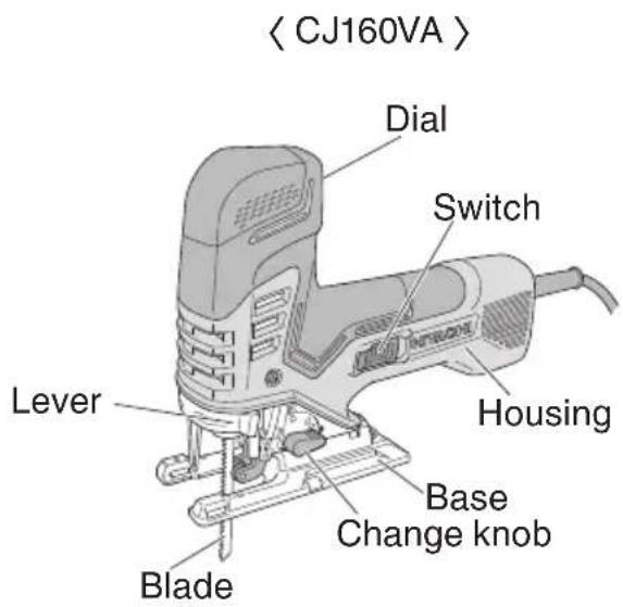
text_image
< CJ160VA > Dial Switch Housing Lever Base Change knob BladeFig. 1
SPECIFICATIONS
| Model CJ160V CJ160VA | ||
| Motor Single-Phase, Series | Commutator Motor | |
| Power Source Single-Phase, 120 V AC 60 Hz | ||
| Capacity | Wood 6-19/64" (160 mm)Aluminum 25/32" (20 mm)Mild steel 25/64" (10 mm) | |
| Current 7.0 A | ||
| No-load speed 800 – 2,800 | /min | |
| Stroke | 1-1/32" (26 mm) | |
| Min. cutting radius | 1" (25 mm) | |
| Weight | 5.5 lbs (2.5 kg) | |
ASSEMBLY AND OPERATION
APPLICATIONS
○ Cutting various lumber and pocket cutting
○ Cutting mild steel plate, aluminum plate, and copper plate
○ Cutting plastics, such as phenol resin and vinyl chloride
○ Cutting thin and soft construction materials
○ Cutting stainless steel plate (With No. 97 blade)
PRIOR TO OPERATION
1. Power source
Ensure that the power source to be utilized conforms to the power source requirements specified on the product nameplate.
2. Power switch
Ensure that the switch is in the OFF position. If the plug is connected to a receptacle while the switch is in the ON position, the power tool will start operating immediately and can cause serious injury.
3. Extension cord
When the work area is far away from the power source, use an extension cord of sufficient thickness and rated capacity. The extension cord should be kept as short as practicable.

text_image
Dam!WARNING
Damaged cord must be replaced or repaired.
4. Check the receptacle
Check the receptacle
If the receptacle only loosely accepts the plug, the receptacle must be repaired. Contact a licensed electrician to make appropriate repairs.
If such a fautly receptacle is used, it may cause overheating, resulting in a serious hazard.
5. Confirming condition of the environment:
Confirm that the work site is placed under appropriate conditions conforming to prescribed precautions.
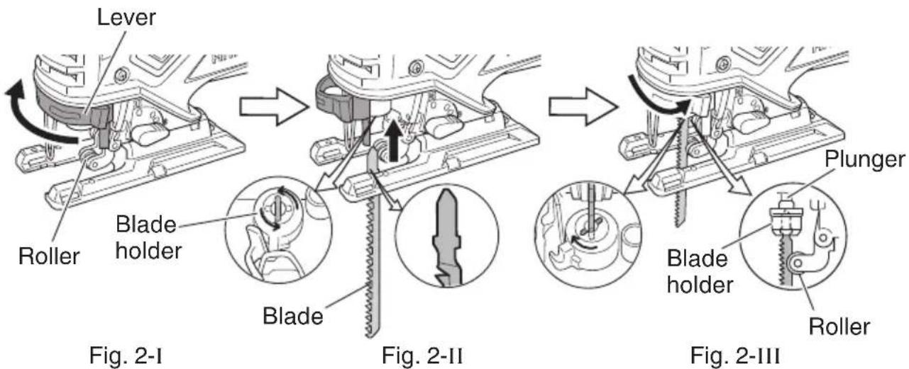
- Changing blades
(1) Pull the lever in the direction indicated by the arrow. (Fig. 2-I)
(2) With the lever pulled, insert the blade until it butts against the outlet of the blade holder tip. (Fig. 2-II)
(3) Release the lever. (Fig. 2-III)
text_image
Lever Roller Blade holder Blade Fig. 2-I Blade Fig. 2-II Plunger Blade holder Roller Fig. 2-IIIFig. 2
CAUTION
- Be sure to switch power OFF and disconnect the plug from the receptacle when changing blades.
● Do not touch the lever when plunger is moving.
NOTE
○ Confirm the protrusions of blade inserted to the blade holder surely.
○ Confirm the blade located between the groove of roller. (Fig. 3)

text_image
Roller Blade Roller BladeFig. 3
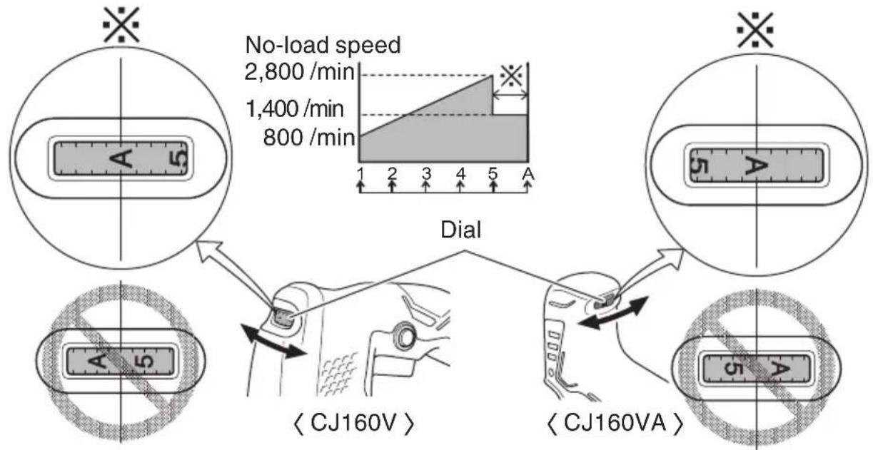
7. Adjusting the blade operating speed
The jig saw is equipped with the electric control circuit which enables stepless speed control. To adjust the speed, turn the dial shown in Fig. 4. When the dial is set to “1”, the jig saw operates at the minimum speed (800 /min). When the dial set to “5”, the jig saw operates at the maximum speed (2,800 /min). Adjust the speed according to the material to be cut and working efficiency.
flowchart
graph TD
    A["No-load speed 2,800/min"] --> B["Dial"]
    C["Instrument placement: A, 5"] --> D["< CJ160V >"]
    E["Instrument placement: 5"] --> F["< CJ160VA >"]
    G["Diagram includes a graph of dial with load speed scale and position markers"]
Fig.4
The tool is equipped with two modes: "Standard Mode" and "AUTO Mode".
(1) Standard Mode
You can change the blade operating speed between 800 to 2,800 /min by adjusting the dial from "1" to "5".
(2) AUTO Mode
Depending on the workload, AUTO Mode "A" will automatically change the blade operating speed to 1,400 /min or 2,800 /min. This has the effect of lowering vibration and noise prior to and during operation.
Adjust the dial for the mode and speed that best suits your task conditions and materials.
Blade operating speed
| Mode Dial Blade operating speed | ||
| Standard Mode 1 – 5 | 800 – 2,800 /min | |
| AUTO Mode | A | No load: 1,400 /minWith load: 2,800 /min |
With AUTO Mode, the vibration frequency may not reach 2,800 /min or return to 1,400 /min depending on variables such as the type of work.
CAUTION
At low speed (dial setting: 1 or 2) do not cut a wood with a thickness of more than 5/16" (8 mm) or metal with a thickness of more than 1/32" (1 mm).
- Adjusting the orbital operation
(1) This Jig Saw employs orbital operation which moves the blade back and forth, as well as up and down. Set the change knob shown in Fig. 5 to "0" to eliminate the orbital operation (the blade moves only up and down). The orbital operation can be selected in 4 steps from "0" to "III".
(2) For the hard material, such as a steel plate, etc., decrease the orbital operation. For the soft material, such as lumber, plastic, etc., increase the orbital operation to increase work efficiency. To cut the material accurately, decrease the orbital operation.
9. Cutting stainless steel plates
This Jig Saw can cut stainless steel plates by using No. 97 blade. Carefully read “Concerning cutting of stainless steel plates” for proper operation.
- Splinter guard
Using the splinter guard when cutting wood materials will reduce splintering of cut surfaces.
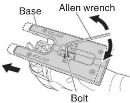
Using the provided Allen wrench, tighten the bolts in the lower area of the base, moving the base as far forward as possible. (See Fig. 6)
Insert the splinter guard in the space on the base, and push it completely. (see Fig. 7)
- Sub base
Used for curved cutting of pieces such as arcs and circles. Makes the task easier by eliminating any snags that may occur between the rear of the base and the material.
Fit into position after hooking the sub base to the tip of the base. (Fig. 8)
To detach, pull up.
NOTE
When the sub base is attached, the blade's protrusion from the material being cut will be reduced by 3mm. When the blade has been moved down to the lowest point, check to make sure that it is protruding from the material.

text_image
Change knobFig. 5
text_image
Base Allen wrench BoltFig. 6

text_image
Splinter guard BaseFig. 7

text_image
Sub Base BaseFig. 8
- Attaching and detaching the chip cover (Fig. 9)

WARNING
To prevent accidents when attaching or detaching the chip cover, make sure the unit is switched off and the power cord is unplugged.
NOTE
The chip cover cannot be attached with the base in an inclined state.
(1) Position the unit at a right angle to the surface (0-degree incline).
(2) Holding the chip cover's guide section open by hand, push into the main unit.
(3) Insert the chip cover's catches into the main unit's slots.
(4) When detaching, spread the catches of the chip cover and draw them out from the main unit's slots.
- Switch Operation (Fig. 10)
The switch will activate when pulled and will deactivate when released.
For continuous operation, pull the switch in all the way and press the stopper.
To cancel continuous operation, once again pull the switch in all the way until the stopper is freed, and then release the switch.
The switch will activate when slid forward and will deactivate when released. For continuous operation, push the switch forward and press the front portion of the switch down to lock it into position.
To unlock and shut off the switch, press the rear portion of the switch.
- How to use the LED light (Fig. 11)
When the switch is turned on, an LED lamp lights to illuminate the end of the blade. This lamp goes out when the switch is released.
CAUTION
Do not look directly into the light from the LED lamp. Continuous and direct exposure to the light from the LED lamp can injure your eyes.

text_image
Chip cover's catches Guide section SlotsFig. 9

text_image
Stopper Switch Trigger < CJ160V > Switch < CJ160VA >Fig. 10

text_image
LED lightFig. 11
CUTTING
CAUTION
In order to prevent blade dislodging, damage or excessive wear on the plunger, please make sure to have surface of the base plate attached to the work piece while sawing.
- Rectilinear cutting
When cutting on a straight line, fi rst draw a marking gauge line and advance the saw along that line. Using the guide (sold separately) will make it possible to cut accurately on line.
(1) Loosen the base bolt allen wrench attached on base. (Fig. 12)
(2) Move the base fully forward, and tighten the base bolt again. (Fig. 12)
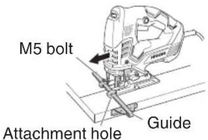
(3) Attach the guide by passing it through the attachment hole on the base and tighten the M5 bolt. (Fig. 13)
(4) Set the orbital position to "0".
NOTE: To ensure accurate cutting when using the Guide (Fig. 13), always set the orbital position to "0".
- Sawing curved lines
When sawing a small circular arc, reduce the feeding speed of the machine. If the machine is fed too fast, it could cause the blade to break.
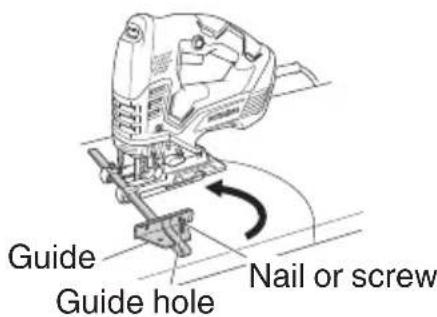
- Cutting a circle or a circular arc
The guide also will be helpful for circular cutting. After attaching the guide by same way noted as above, drive the nail or screw into the material through the hole on the guide, then use it for a axis when cutting. (Fig. 14)
NOTE: Circular cutting must be done with the blade approximately vertical to the bottom surface of the base.
- Cutting metallic materials
(1) Adjust the speed Dial between scales "3" and "4".
(2) Set the orbital position to "0" or "I".
(3) Always use an appropriate cutting fluid (spindle oil, soapy water, etc.). When a liquid cutting fluid is not available, apply grease to the back surface of the material to be cut.
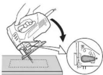
- Pocket cutting (Fig. 15)
(1) In lumber
Aligning the blade direction with the grain of the wood, cut step by step until a window hole is cut in the center of the lumber.

text_image
Base Allen wrench BoltFig. 12
text_image
M5 bolt Attachment hole GuideFig. 13
text_image
Guide Guide hole Nail or screwFig. 14
text_image
Diagram illustrating a hand using a tool to cut a component, with an inset showing the magnified view of the component's internal structure.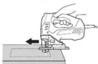
natural_image
Illustration of a hand operating a power tool on a workbench, with no visible text or symbols.Fig. 15
(2) In other materials
When cutting a window hole in materials other than lumber, initially bore a hole with a drill or similar tool from which to start cutting.
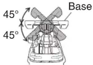
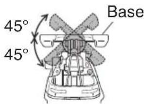
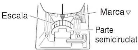
6. Angular cutting
The base can be swiveled to both sides by up to 45^ for angular cutting. (Fig. 16)
(1) Loosen the base bolt by allen wrench attached on base and move the base fully forward. (Fig. 12)
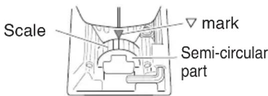
(2) Align the scale (from 0 degrees to 45 degrees by 15-degree increments) of the semi-circular part of the base with the [▽] mark on the gear cover. (Fig. 17)
(3) Tighten the M5 bolt again. (Fig. 12)
(4) Set the orbital position to "0".
NOTE: Angular cutting can not be done when adopting chip cover or dust collector.
text_image
45° 45° Base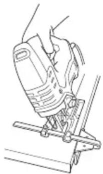
natural_image
Line drawing of a hand using a power tool on a metal bracket (no text or symbols)Fig. 16
text_image
Scale mark Semi-circular partFig. 17
CONCERNING CUTTING OF STAINLESS STEEL PLATES
When used with the No. 97 blade, can cut stainless steel plates.
Note the following to adjust the unit.
CAUTION
In order to prevent blade dislodging, damage or excessive wear on the plunger, please make sure to have surface of the base plate attached to the work piece while sawing.
When cutting stainless steel plates, adjust the unit as described below:
1. Adjust the speed
| Blade Thickness of material Dial Scale | |
| No. 97 1/16" – 5/32" (1.5 mm – 2.5 mm) | Middle groove position between scales “2” and “3” |
NOTE: Dial scale reading is for reference only. The higher the speed is, the quicker the material is cut. But the service life of the blade will be reduced in this case. When the speed is too low, cutting will take longer, although the service life will be prolonged. Make adjustments as desired.
2. Set the orbital position to "0"
NOTE: When cutting use cutting fluid (oil base cutting fluid) to prolong the blade's service life.
SELECTION OF BLADES
○ Accessory blades
To ensure maximum operating efficiency and results, it is very important to select the appropriate blade best suited to the type and thickness of the material to be cut. Three types of blades are provided as standard accessories. The blade number is engraved in the vicinity of the mounting portion of each blade. Select appropriate blades by refer (page 17).
HOUSING THE ALLEN WRENCH
○ It is possible to house the axiliary allen wrench on the base (see Fig. 18).
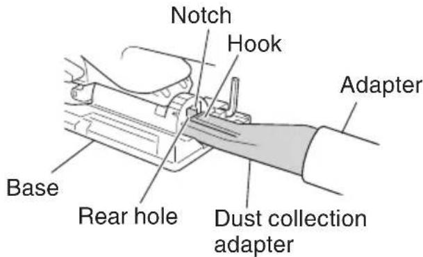
CONNECTING WITH CLEANER
By connecting with cleaner (sold separately) through dust collection adapter and adapter (sold separately), most of dust can be collected.
(1) Remove the allen wrench from the base.
(2) Move the base fully forward. (Fig.12)
(3) Connect the dust collection adapter with adapter. (Fig. 19)
(4) Connect the adapter with the nose of cleaner. (Fig. 19)
(5) Insert dust collection adapter into the rear hole of the base until the hook catches in the notch. (Fig. 20)
(6) Press the hook to remove the dust collection adapter.

text_image
Allen wrench BaseFig. 18

text_image
Adapter Nose Base Dust collection adapter CleanerFig. 19
text_image
Notch Hook Adapter Base Rear hole Dust collection adapterFig. 20
MAINTENANCE AND INSPECTION
⚠ WARNING: Be sure to switch power OFF and disconnect the plug from the receptacle during maintenance and inspection.
- Inspecting the blade
Continued use of a dull or damaged blade will result in reduced cutting efficiency and may cause overloading of the motor. Replace the blade with a new one as soon as excessive abrasion is noted.
- Maintenance of the motor
The motor unit winding is the very “heart” of the power tool. Exercise due care to ensure the winding does not become damaged and/or wet with oil or water.
⚠ WARNING: Using this Jig Saw with loosen screws is extremely dangerous.
- Maintenance of the motor
The motor unit winding is the very “heart” of the power tool. Exercise due care to ensure the winding does not become damaged and/or wet with oil or water.
- Service and repairs
All quality power tools will eventually require servicing or replacement of parts because of wear from normal use. To assure that only authorized replacement parts will service and repairs must be performed by a HITACHI AUTHORIZED SERVICE CENTER, ONLY.
- Service parts list
CAUTION: Repair, modification and inspection of Hitachi Power Tools must be carried out by an Hitachi Authorized Service Center.
This Parts List will be helpful if presented with the tool to the Hitachi Authorized Service Center when requesting repair or other maintenance. In the operation and maintenance of power tools, the safety regulations and standards prescribed in each country must be observed.
MODIFICATIONS:
Hitachi Power Tools are constantly being improved and modified to incorporate the latest technological advancements.
Accordingly, some parts may be changed without prior notice.
Table 1 List of appropriate blades
| Material to be cut | Blade Material quality | No. 1 (Super Long) | No. 11 | No. 12 | No. 15 | No. 16 | No. 21 | No. 22 | No. 31 | No. 41 | No. 97 |
| Thickness of material: inch (mm) | |||||||||||
| Lumber | General lumber | Below 5-5/16 (135) | 3/8-2-5/32 (10-55) | Below 3/4 (20) | 3/8-2-5/32 (10-55) | 3/16-1-9/16 (5-40) | 3/4-2-5/32 (20-55) | 3/8-2-9/16 (10-65) | |||
| Plywood | 3/16-1-3/16 (5-30) | Below 3/8 (10) | 3/16-1-3/16 (5-30) | 1/8-3/4 (3-20) | |||||||
| Iron plate | Mild steel plate | 1/8-15/64 (3-6) | Below 1/8 (3) | 5/64-3/16 (2-5) | |||||||
| Stainless steel plate | 1/16-5/32 (1.5-2.5) | ||||||||||
| Nonferrous metal | Aluminium, copper, brass | 1/8-15/32 (3-12) | Below 1/8 (3) | Below 3/16 (5) | |||||||
| Aluminium sash | Height up to 63/64 (25) | Height up to 63/64 (25) | |||||||||
| Plastics | Phenol resin, melamin resin, etc. | 3/16-3/4 (5-20) | Below 1/4 (6) | 3/16-19/32 (5-15) | Below 1/4 (6) | 3/16-19/32 (5-15) | |||||
| Vinyl chloride, acryl resin, etc. | 3/16-1-3/16 (5-30) | Below 3/8 (10) | 3/16-3/4 (5-20) | Below 3/16 (5) | 3/16-1-3/16 (5-30) | 1/8-3/4 (3-20) | 3/16-19/32 (5-15) | ||||
| Foamed polyethylene, foamed styrol | 3/8-2-5/32 (10-55) | 1/8-63/64 (3-25) | 3/16-63/64 (5-25) | 1/8-63/64 (3-25) | 3/8-2-5/32 (10-55) | 1/8-1-1/2 (3-40) | 3/16-63/64 (5-25) | ||||
| Pulp | Card board, corrugated paper | 3/8-2-5/32 (10-55) | 1/8-63/64 (3-25) | 3/8-2-5/32 (10-55) | 1/8-1-1/2 (3-40) | ||||||
| Hardboard | 1/8-63/64 (3-25) | Below 1/4 (6) | 1/8-63/64 (3-25) | ||||||||
| Fiberboard | Below 1/4 (6) | ||||||||||
NOTE:
☐ The minimum cutting radius of No. 1 (Super Long), No. 21, No. 22, No. 31 and No. 41 blades is 3-15/16" (100 mm).
☐ Blades except No. 41 are sold separately.
ACCESSORIES

WARNING: ALWAYS use Only authorized HITACHI replacement parts and accessories. NEVER use replacement parts or accessories which are not intended for use with this tool. Contact HITACHI if you are not sure whether it is safe to use a particular replacement part or accessory with your tool.
The use of any other attachment or accessory can be dangerous and could cause injury or mechanical damage.
NOTE: Accessories are subject to change without any obligation on the part of the HITACHI.
STANDARD ACCESSORIES
○ No. 41 Blade ....1
○ No. 42 Blade ....1
○ No. 123X Blade ....10
○ Allen wrench (Code No. 944458)....1
○ Splinter guard (Code No. 338994)....1
○ Chip Cover (Code No. 338996) ...... 1
○ Dust collection adapter (Code No. 321591)....1
○ Case....1
○ Sub base (Code No. 339018)....1
OPTIONAL ACCESSORIES.....sold separately
○ No. 1 Blade (Super Long) (Code No. 321878)
O No. 11 Blade (Code No. 963390)
○ No. 12 Blade (Code No. 963391)
○ No. 15 Blade (Code No. 963392)
○ No. 16 Blade (Code No. 963393)
O No. 21 Blade (Code No. 963394)
○ No. 22 Blade (Code No. 963395)
○ No. 31 Blade (Code No. 879356)
O No. 97 Blade (Code No. 963400)
○ Guide (Code No. 879391)
NOTE: Specifications are subject to change without any obligation on the part of the HITACHI.
CONSIGNES DE SÉCURITÉ IMPORTANTES
natural_image
Diagram of a vehicle's door and seat assembly with directional arrows indicating motion (no text or symbols)text_image
Diagram illustrating a sewing process with a hand using a sewing machine and a magnified inset showing the sewing machine's base.
natural_image
Illustration of a hand using a power tool to cut a piece of paper (no text or symbols visible)Fig. 15

text_image
45° 45° Base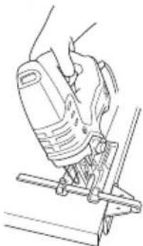
natural_image
Line drawing of a hand using a power tool to lift or stand (no text or symbols)Fig. 16

text_image
Echelle Repère ▼ Section semi- circulaireFig. 17
AU SUJET DU DECOUPAGE DE PLAQUES EN ACIER INOXYDABLE
natural_image
Black and white illustration of a hand with a lightning bolt symbol (no text or numbers)ADVERTENCIA:
text_image
Diagram illustrating a hand using a power tool to cut a component, with an inset showing the same component.
natural_image
Illustration of a hand using a J-turn tool to cut a piece of paper (no text or symbols visible)Fig. 15
text_image
45° 45° Base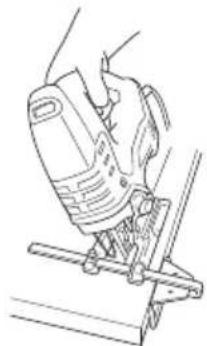
natural_image
Line drawing of a hand using a power tool on a metal base (no text or symbols)Fig. 16
text_image
Escala Marca Parte semiciruclatFig. 17
text_image
Exploded view diagram of a washing machine with numbered parts and exploded viewCJ160VA
| Item No. | Part Name Q'TY | |
| 42 | WEIGHT1HOLDER | 1 |
| 43 | BALANCE WEIGHT | 1 |
| 44 | GEAR | 1 |
| 45 | ORBITAL CAM | 1 |
| 46 | WASHER (A) | 1 |
| 47 | ORBITAL PIN | 1 |
| 48 | FELT | 1 |
| 49 | GEAR COVER | 1 |
| 50 | PLATE NOT 2 | 1 |
| 51 | LEVER SPRING 1 | |
| 52 | LEVER | 1 |
| 53 | LEVER BOLT | 1 |
| 54 | SPRING | 1 |
| 55 | PLUNGER (B) | 1 |
| 56 | HOLDER SPRING | 1 |
| 57 | HOLDER COVER | 1 |
| 58 | RETAINING RING FOR D18 HOLE | 1 |
| 59 | PLUNGER COVER | 1 |
| 60 | HOLDER PIN | 1 |
| 61 | BASE | 1 |
| 62 | MACHINE SCREW(W/WASHER) M4 | 1 |
| 63 | RUBBER BUSHING | 1 |
| 64 | ROLLER HOLDER | 1 |
| 65 | RETAINING RING (E-TYPE)FOR D5 SHAFT | 1 |
| 66 | NEEDLE ROLLER | 4 |
| 67 | BASE LOCKER | 1 |
| 68 | HEX. SOCKET HD. BOLTM5X18 | 1 |
| 69 | CHANGE KNOB | 1 |
| 70 | SPRING (C) | 1 |
| 71 | STEEL BALL D3.97 | 1 |
| 72 | BASE PLATE | 1 |
| 73 | SPECIAL BOLT | 4 |
| 501 | CASE | 1 |
| 502 | BLADE (42) | 1 |
| 503 | BLADE (123X) | 10 |
| 504 | BLADE (41) | 1 |
| 505 | CHIP COVER | 1 |
| 506 | DUST COLLECTOR | 1 |
| 507 | HEX. BAR WRENCH 4MM | 1 |
| 508 | SPLINTER GUARD | 1 |
| 509 | SUB BASE | 1 |
| Item No. | Part Name Q'TY | |
| 1 | H O U S I N | G |
| 2 RUBBER COVER 2 | ||
| 3 | SEAL LOCK SCREW(W/WASHER) M4X10 | 2 |
| 4 | S L I D E K | N |
| 5 | ARMATURE ASS'Y(MAGNET) | 1 |
| 6 BALL BEARING 1 | ||
| 7 | B R U S H H | O |
| 8 | C A R B O N | B |
| 9 RUBBER RING 1 | ||
| 10 BEARING BUSH 1 | ||
| 11 SENSOR MAGNET | 1 | |
| 12 PUSHING NUT | 1 | |
| 13 | STATOR | 1 |
| 15 | LED (A) | 1 |
| 17 | TAPPING SCREW(W/FLANGE) D4X40 | 1 |
| 18 | TAPPING SCREW(W/FLANGE) D4X20 | 6 |
| 19 | NAME PLATE | 1 |
| 20 TERMINAL M3.5 | 2 | |
| 21 CONNECTOR 50091 1 | ||
| 22 PILLAR TERMINAL | 1 | |
| 23 CONTROLLER | 1 | |
| 24 SLIDE BAR | 1 | |
| 25 | MACHINE SCREW(W/WASHER) M3.5X6 | 2 |
| 26 SWITCH | 1 | |
| 27 CORD CLIP | 1 | |
| 28 | TAPPING SCREW(W/FLANGE) D4X16 | 2 |
| 29 TERMINAL | 1 | |
| 30 CORD ARMOR 1 | ||
| 31 CORD | 1 | |
| 32 FT SCREW M4X13.5 | 4 | |
| 33 GUARD BAR | 1 | |
| 34 UPPER COVER | 1 | |
| 35 GUIDE PLATE | 1 | |
| 36 SEAL LOCK SCREW M4X10 | 4 | |
| 37 CONNECTING PIECE | 1 | |
| 38 | NEEDLE BEARING NTNK6X9X8T2 | 1 |
| 39 | RETAINING RING FOR D8SHAFT | 1 |
| 40 WASHER (B) | 1 | |
| 41 | SEAL LOCK HEX. SOCKETHD. BOLT M4X12 | 2 |

text_image
Exploded view diagram of a mechanical assembly with numbered parts and exploded viewsWARNING:
Some dust created by power sanding, sawing, grinding, drilling, and other construction activities contains chemicals known to the State of California to cause cancer, birth defects or other reproductive harm. Some examples of these chemicals are:
- Lead from lead-based paints,
- Crystalline silica from bricks and cement and other masonry products, and
- Arsenic and chromium from chemically-treated lumber.
Your risk from these exposures varies, depending on how often you do this type of work. To reduce your exposure to these chemicals: work in a well ventilated area, and work with approved safety equipment, such as those dust masks that are specially designed to filter out microscopic particles.
AVERTISSEMENT:
Shinagawa Intercity Tower A, 15-1, Konan 2-chome, Minato-ku, Tokyo 108-6020, Japan
Distributed by

Hitachi Koki U.S.A., Ltd.
PO Box 970
Braselton, GA 30517

Hitachi Koki Canada Corp.
450 Export Blvd. Unit B, Mississauga ON L5S 2A4
507
Code No. C99713761 F
Printed in China