
C10RJ - Saw HITACHI - Free user manual and instructions
Find the device manual for free C10RJ HITACHI in PDF.
| Product Type | Benchtop Table Saw |
| Brand | Hitachi |
| Model | C10RJ |
| Power Supply | 120 V ~ 60 Hz, 15 A |
| No-Load Speed | 4500 RPM |
| Blade Type | Carbide-tipped blade 10 in x 5/8 in (255 mm x 15.9 mm), 40 teeth |
| Bevel Range | 0° to 45° |
| Work Table Dimensions | 730 mm x 559 mm (28-3/4 in x 22 in) |
| Outfeed Support Dimensions | 730 mm x 50 mm (28-3/4 in x 2 in) |
| Cutting Depth at 0° | 79 mm (3-1/8 in) |
| Cutting Depth at 45° | 57 mm (2-1/4 in) |
| Max Rip Capacity Left of Blade | 559 mm (22 in) |
| Max Rip Capacity Right of Blade | 889 mm (35 in) |
| Max Dado Width | 20 mm (13/16 in) |
| Weight | 44 kg (96 lb) |
| Safety | Double insulation, blade guard, riving knife, anti-kickback pawls, overload circuit breaker, switch lock |
| Included Accessories | Blade guard, anti-kickback pawls, rip fence, outfeed support, miter gauge, push stick, blade wrenches, stand, wheels, handle |
| Maintenance | Regular cleaning, no lubrication required (lifetime lubricated bearings), blade replacement, check stops and alignment |
| Repairability | Repairs by Hitachi authorized center only, original spare parts |
Frequently Asked Questions - C10RJ HITACHI
User questions about C10RJ HITACHI
0 question about this device. Answer the ones you know or ask your own.
Ask a new question about this device
Download the instructions for your Saw in PDF format for free! Find your manual C10RJ - HITACHI and take your electronic device back in hand. On this page are published all the documents necessary for the use of your device. C10RJ by HITACHI.
USER MANUAL C10RJ HITACHI
natural_image
Technical line drawing of a tracked robotic platform with visible legs, wheels, and structural components (no text or symbols)SAFETY INSTRUCTIONS AND INSTRUCTION MANUAL
WARNING
IMPROPER OR UNSAFE use of this power tool can result in death or serious bodily injury!
This manual contains important information about product safety. Please read and understand this manual BEFORE operating the power tool. Please keep this manual available for other users and owners before they use the power tool. This manual should be stored in safe place.
INSTRUCTIONS DE SECURITE ET MODE D'EMPLOI
AVERTISSEMENT
Service under this warranty is available from Hitachi Koki U.S.A., Ltd. at:
IN THE U.S.A. IN CANADA
3950 Steve Reynolds Blvd. Norcross, GA 30093
6395 Kestrel Road Mississauga, ON L5T 1Z5
9409 Owensmouth Ave. Chatsworth, CA 91311
OR CALL: (800) 970-2299 for a service center nearest you.
OR CALL: (800) 546-1666 for a service center nearest you.
TABLE DES MATIÈRES
| Français | PAGESECTION | PAGESECTION | |
| SYMBOLES DE SÉCURITÉ | 46 | ASSEMBLAGE | |
| CONSIGNES DE SÉCURITÉ | 47 | FONCTIONNEMENT | |
| GLOSSAIRE DES TERMES | 55 | RÉGLAGES | |
| VUE D'ENSEMBLE | 57 | ENTRETIEN | |
| CARACTÉRISTIQUES TECHNIQUES | 59 | GUIDE DE DÉPANNAGE | |
| PIÈCES DÉTACHÉES | 60 | LISTE DES PIÈCES | |
CENTRES TECHNIQUES HITACHI AGREES
3950 Steve Reynolds Blvd. Norcross, GA 30093
AU CANADA
9409 Owensmouth Ave. Chatsworth, CA 91311
6395 Kestrel Road Mississauga, ON L5T 1Z5
3950 Steve Reynolds Blvd. Norcross, GA 30093
EN CANADA
9409 Owensmouth Ave. Chatsworth, CA 91311
6395 Kestrel Road Mississauga, ON L5T 1Z5
IMPORTANT SAFETY INFORMATION
Read and understand all of the safety precautions, warnings and operating instructions in the Instruction Manual before operating or maintaining this power tool.
Most accidents that result from power tool operation and maintenance are caused by the failure to observe basic safety rules or precautions. An accident can often be avoided by recognizing a potentially hazardous situation before it occurs, and by observing appropriate safety procedures.
Basic safety precautions are outlined in the "SAFETY" section of this Instruction Manual and in the sections which contain the operation and maintenance instructions.
Hazards that must be avoided to prevent bodily injury or machine damage are identified by WARNINGS on the power tool and in this Instruction Manual.
NEVER use this power tool in a manner that has not been specifically recommended by HITACHI.
SAFETY SYMBOLS
Some of these following symbols may be used on this tool. Please study them and learn their meaning. Proper interpretation of these symbols will allow you to operate the tool better and safer.
| Designation / ExplanationNameSymbol | ||
| VoltageVoltsv | ||
| CurrentAmperesA | ||
| Frequency (cycles per second)HertzHz | ||
| PowerWattsW | ||
| Type of currentAlternating current~ | ||
| --- | Type of characteristic of currentDirect current | |
| Rotational speed at no loadNo-load speedno | ||
| .../min | Per minute | Revolutions, strokes, surface speed orbits, etc., per minute |
 | Class II construction | Double insulated construction |
| [SKZT] | Be careful of your hand | Danger keep hands away from blade |
 | Eye protection | Always wear safety goggles or safety glasses with side shields and, as necessary, a full face shield when operating this product. |
The following signal words and meanings are intended to explain the levels of risk associated with this product.
| MeaningSignalSymbol | ||
| ⚠️ | DANGER: | Indicates an imminently hazardous situation, which, if not avoided, will result in death or serious injury. |
| ⚠️ | WARNING: | Indicates a potentially hazardous situation, which, if not avoided, could result in death or serious injury |
| ⚠️ | CAUTION: | Indicates a potentially hazardous situation, which, if not avoided, may result in minor or moderate injury. |
| CAUTION: | (Without Safety Alert Symbol) Indicates a situation that may result in property damage. |
WARNING:

The operation of any power tool can result in foreign objects being thrown into your eyes, which can result in severe eye damage. Before beginning power tool operation, always wear safety goggles or safety glasses with side shields and a full-face shield when needed. We recommend a Wide Vision Safety Mask for use over eyeglasses or standard safety glasses with side shields. Always use eye protection which is marked to comply with ANSI Z87.1. Everyday eyeglasses have only impact resistant lenses. They are NOT safety glasses.
⚠ WARNING: To ensure safety and reliability, all repairs should be performed by a qualified service technician.
SAFETY INSTRUCTIONS
⚠ WARNING: Read and understand all instructions. Failure to follow all instructions listed below, may result in electric shock, and/or serious personal injury. Save all warnings and instructions for future reference.
GENERAL SAFETY IMFORMATION
PROPOSITION 65 WARNING
Some dust created by using power tools contain chemicals known to the state of California to cause cancer, birth defects or other reproductive harm. Some examples of these chemicals are:
- Lead from lead-based paints.
- Crystalline silica from bricks and cement and other masonry products, and
- Arsenic and chromium from chemically treated lumber.
Your risk from these exposures varies depending on how often you do this type of work. To reduce your exposure to these chemicals: work in a well ventilated area and work with approved safety equipment, such as dust masks that are specially designed to filter out microscopic particles.
Avoid prolonged contact with dust from power sanding, sawing, grinding, drilling, and other construction activities. Wear protective clothing and wash exposed areas with soap and water. Allowing dust to get into your mouth or eyes or to lie on the skin may promote absorption of harmful chemicals.
⚠WARNING: The use of this tool can generate and/or disperse dust, which may cause serious and permanent respiratory or other injury. Always use protection appropriate for the dust exposure. Direct particles away from the face and body.
Handling the power cord on this product may expose you to chemicals known to the State of California to cause cancer and birth defects or other reproductive harm. Wash hands after handling.
⚠️CAUTION: Always follow proper operating procedures as defined in this manual — even if you are familiar with use of this or similar tools. Remember that being careless for even a fraction of a second can result in severe personal injury.
⚠ WARNING: To avoid the risk of personal injury, do not modify this power tool or use accessories not recommended to your tool.
⚠ WARNING: Read warnings and conditions about your carbide tipped saw blade.
⚠ WARNING: Do not operate the saw without the proper blade guard in place for all through cut operations. Make sure the blade guard is reinstalled immediately after finishing any non-through cut operations which require removal of the blade guard.
natural_image
Pure mechanical assembly diagram without any text, numbers, or symbols- Carbide is a very hard but brittle material. Care should be taken while mounting, using and storing carbide tipped blades to prevent accidental damage.
- Slight shocks, such as striking the tip, can seriously damage the blade. Foreign objects on the work piece, such as wire or nails, can also cause tips to crack or break off.
- Before using, always visually examine the blade and tips for cracks, breakage, missing or loose tips, or other damage.
- Do not use if damage is suspected. Failure to heed safety instructions and warnings can result in serious bodily injury or loss of eyesight.
GENERAL SAFETY RULES
- READ INSTRUCTION MANUAL AND KNOW YOUR TOOL. Read and familiarize yourself with entire instruction manual. Learning the tool's proper applications. Limitations, and specific potential hazards will greatly minimize the possibility of accidents and injury. Make sure all users are familiar with its warnings and instructions before using tool.
- GUARD AGAINST ELECTRICAL SHOCK BY PREVENTING BODY CONTACT WITH GROUNDED SURFACES. For example, pipes, radiators, ranges, refrigerator enclosures.
- KEEP GUARDS IN PLACE and in good working order. Blade guard must be in place for all through cut operations. Reinstall the blade guard immediately after finishing any non-through cut operations which require removal of the blade guard. Never operate the saw without the blade guard in place for any cut which does not require it to be removed. Make sure the blade guard is operating properly before each use. A guard that is loose, damaged, or is not functioning correctly must be repaired or replaced.
- MAKE SURE THE SAW BLADE IS NOT CONTACTING THE GUARD, RIVING KNIFE OR THE WORKPIECE BEFORE THE SWITCH IS TURNED ON. Inadvertent contact of these items with the saw blade could cause a hazardous condition
- REMOVE ADJUSTING KEYS AND WRENCHES. Form habit of checking to see that keys and adjusting wrenches are removed from tool before turning it on.
- KEEP WORK AREA CLEAN. Cluttered areas and benches invite accidents. DO NOT leave tools or pieces of wood on the saw while it is in operation. Distraction or a potential jam can be dangerous.
- DO NOT USE IN DANGEROUS ENVIRONMENTS. Do not use power tools in damp or wet locations or expose to rain. Keep the work area well lit. Locate the tool in a level area. It should be installed in an area that provides enough room to easily handle the size of your workpiece. Cramped, dark areas, and uneven slippery floors invite accidents.
- KEEP CHILDREN AND VISITORS AWAY. All visitors should wear safety glasses and be kept a safe distance from work area. Do not let visitors contact tool or extension cord while operating.
- MAKE WORKSHOP CHILDPROOF with padlocks and master switches, or by removing starter keys.
- DON'T FORCE TOOL. It will do the job better and safer at the feed rate for which it was designed.
- FEED WORKPIECE AT AN EVEN PACE. DO NOT BEND OR TWIST THE WORKPIECE. IF JAMMING OCCURS, TURN THE TOOL OFF IMMEDIATELY, UNPLUG THE TOOL THEN CLEAR THE JAM. Jamming the saw blade by the workpiece can cause kickback or stall the motor.
- USE RIGHT TOOL. Don't force the tool or attachment to do a job it was not designed for. Don't use it for a purpose not intended.
- USE THE PROPER EXTENSION CORD. Make sure your extension cord is in good condition. Use only a cord heavy enough to carry the current your product will draw. An undersized cord will cause a drop in line voltage resulting in loss of power and overheating. A wire gauge size (A.W.G.) of at least 14 is recommended for an extension cord 25 feet or less in length. If in doubt, use the next heavier gauge. The smaller the gauge number, the heavier the cord.
- DRESS PROPERLY. Do not wear loose clothing, gloves, neckties, or jewelry. They can get caught and draw you into moving parts. Rubber gloves and nonskid footwear are recommended when working outdoors. Also wear protective hair covering to contain long hair.
- ALWAYS wear safety goggles that comply with United States ANSI Z87.1 and a face shield or dust mask if operation is dusty. Everyday eyeglasses have only impactresistant lenses, they are NOT safety glasses.
- SECURE WORK. Use a clamps or vice to hold workpiece when practical. It's safer than using your hand and frees both hands to operate tool.
- DON'T OVERREACH. Keep proper footing and balance at all times.
- MAINTAIN TOOLS WITH CARE. Keep tools sharp and clean for better and safer performance. Follow instructions for lubricating and changing accessories.
- DISCONNECT TOOLS. All tools should be disconnected when not in use, before servicing, or when changing attachments, blades, bits, cutters, etc. Turn the machine "OFF" before disconnecting tools to avoid an accidental start when plugging the tools in again. The accidental start may cause serious injury. Do not touch the terminal or plug's metal part when inserting or removing the plug from an outlet.
- DO NOT PLUG IN OR PULL OUT FROM POWER SUPPLY WITH WET HANDS TO PREVENT ELECTRIC SHOCK.
- USE RECOMMENDED ACCESSORIES. Consult the operator's manual for recommended accessories.
The use of improper accessories may risk injury.
- NEVER STAND ON TOOL. Serious injury could occur if the tool is tipped or if the cutting tool is unintentionally contacted. Do not use it as a stepping stool.
- CHECK DAMAGED PARTS. Before further use of the tool, a guard or other part that is damaged should be carefully checked to determine that it will operate properly and perform its intended function. Check for alignment of moving parts, binding of moving parts, breakage of parts, mounting and any other conditions that may affect its operation. A guard or other part that is damaged must be properly repaired or replaced by an authorized service center to avoid risk of personal injury.
- USE THE RIGHT DIRECTION OF FEED. Feed workpiece into a blade or cutter against the direction of rotation of blade or cutter only. Feeding the workpiece in the same direction that the saw blade is rotating above the table may result in the workpiece, and your hand, being pulled into the saw blade.
- NEVER LEAVE TOOL RUNNING UNATTENDED. Turn the power off. Don't leave tool until it comes to a complete stop. An unattended running saw is an uncontrolled hazard.
- PROTECT YOUR LUNGS. Wear a face or dust mask if the cutting operation is dusty.
- PROTECT YOUR HEARING. Wear ear plugs or muffs during extended periods of operation.
- DO NOT ABUSE CORD. Never yank cord to disconnect from receptacle. Keep cord away from heat, oil, and sharp edges.
- WHEN OPERATING A POWER TOOL OUTSIDE, USE AN OUTDOOR EXTENSION CORD MARKED "W-A" OR "W". These cords are rated for outdoor use and reduce the risk of electric shock.
- ALWAYS KEEP THE BLADE GUARD AND SPREADER (RIVING KNIFE) IN PLACE and in working order for all through cut operations. Reinstall the blade guard immediately after finishing any non-through cut operations which require removal of the blade guard.
- ADJUST THE RIVING KNIFE AS DESCRIBED IN THIS INSTRUCTION MANUAL. Incorrect spacing, positioning and alignment can make the riving knife ineffective in reducing the likelihood of kickback.
- FOR THE RIVING KNIFE AND ANTI-KICKBACK PAWLS TO WORK, THEY MUST BE ENGAGED IN THE WORKPIECE. The riving knife and anti-kickback pawls are ineffective when cutting workpieces that are too short to be engaged with the riving knife and anti-kickback pawls. Under these conditions a kickback cannot be prevented by the riving knife and anti-kickback pawls.
- USE THE APPROPRIATE SAW BLADE FOR THE RIVING KNIFE. For the riving knife to function properly, the saw blade diameter must match the appropriate riving knife and the body of the saw blade must be thinner than the thickness of the riving knife and the cutting width of the saw blade must be wider than the thickness of the riving knife.
- KEEP BLADES CLEAN, SHARP, AND WITH SUFFICIENT SET. Sharp blades minimize stalling and kickback.
- KEEP HANDS AWAY FROM CUTTING AREA. Keep hands away from blades. Do not reach underneath work or around or over the blade while blade is rotating. Do not attempt to remove cut material when blade is moving. The material may become trapped between the fence or inside the saw blade guard and the saw blade pulling your fingers into the saw blade. Turn the saw off and wait until the saw blade stops before removing material.
- BLADE COASTS AFTER BEING TURNED OFF.
- NEVER USE IN AN EXPLOSIVE ATMOSPHERE. Normal sparking of the motor could ignite fumes.
- INSPECT TOOL CORDS PERIODICALLY. If damaged, have repaired by a qualified service technician at an authorized service facility. The conductor with insulation having an outer surface that is green with or without yellow stripes is the equipment-grounding conductor. If repair or replacement of the electric cord or plug is necessary, do not connect the equipment-grounding conductor to a live terminal. Repair or replace a damaged or worn cord immediately. Stay constantly aware of cord location and keep it well away from the rotating blade.
- INSPECT EXTENSION CORDS PERIODICALLY and replace if damaged.
- GROUND ALL TOOLS. If tool is equipped with three-prong plug, it should be plugged into a three-hole electrical receptacle.
- CHECK WITH A QUALIFIED ELECTRICIAN or service personnel, if the grounding instructions are not completely understood, or if in doubt as to whether the tool is properly grounded.
-
USE ONLY CORRECT ELECTRICAL DEVICES: 3-wire extension cords that have 3-prong grounding plugs and 3-hole receptacles that accept the tool's plug.
-
DO NOT MODIFY the plug provided. If it will not fit the outlet, have the proper outlet installed by a qualified electrician.
- KEEP TOOL DRY, CLEAN, AND FREE FROM OIL AND GREASE. Always use a clean cloth when cleaning. Never use brake fluids, gasoline, petroleum-based products, or any solvents to clean tool.
- STAY ALERT AND EXERCISE CONTROL. Watch what you are doing and use common sense. Do not operate tool when you are tired. Do not rush.
- DO NOT USE TOOL IF SWITCH DOES NOT TURN IT ON AND OFF. Have defective switches replaced by an authorized service center.
- USE ONLY CORRECT BLADES. Do not use blades with incorrect size holes. Never use blade washers or blade bolts that are defective or incorrect. The maximum blade capacity of your saw is 10 in. Blades that do not match the mounting hardware of the saw will run off-center, causing loss of control.
- BEFORE MAKING A CUT, BE SURE ALL ADJUSTMENTS ARE SECURE.
- BE SURE BLADE PATH IS FREE OF NAILS. Inspect for and remove all nails from lumber before cutting.
- NEVER TOUCH BLADE or other moving parts during use.
- FIRMLY MOUNT THE TOOL ON A SECURE SURFACE TO ENSURE ITS STABILITY BEFORE OPERATING THE TOOL.
- NEVER START A TOOL WHEN ANY ROTATING COMPONENT IS IN CONTACT WITH THE WORKPIECE.
• DO NOT OPERATE A TOOL WHILE UNDER THE INFLUENCE OF DRUGS, ALCOHOL, OR ANY MEDICATION. - WHEN SERVICING use only identical replacement parts. Use of any other parts may create a hazard or cause product damage.
- USE ONLY RECOMMENDED ACCESSORIES listed in this manual or addendums. Use of accessories that are not listed may cause the risk of personal injury. Instructions for safe use of accessories are included with the accessory.
- DOUBLE CHECK ALL SETUPS. Make sure blade is tight and not making contact with saw or workpiece before connecting to power supply.
- DO NOT ALLOW FAMILIARITY (gained from frequent use of your saw) TO CAUSE A CARELESS MISTAKE. Always remember that a careless fraction of a second is sufficient to inflict serious injury. Use extra caution and keep your attention on your operation when making repetitive cuts. Reduce the monotony of operations by frequently taking breaks, cleaning up saw dust, or checking the tool condition.
SPECIFIC SAFETY RULES
- FIRMLY BOLT THE SAW TO A WORK BENCH OR LEG STAND at approximately hip height.
- NEVER OPERATE THE SAW ON THE FLOOR.
- KEEP GUARDS IN PLACE and in good working order. Blade guard must be in place for all through cut operations. Reinstall the blade guard immediately after finishing any non-through cut operations which require removal of the blade guard.
- GUARD AGAINST KICKBACK. Kickback occurs when the blade stalls rapidly and workpiece is driven back towards the operator. It can pull your hand into the blade resulting in serious personal injury. Stay out of blade path and turn switch off immediately if blade binds or stalls.
- USE RIP FENCE. Always use a fence or straight edge guide when ripping.
- USE AN AUXILIARY FENCE IN CONTACT WITH THE TABLE TOP WHEN RIPPING WORKPIECES LESS THAN 5/64" (2 MM) THICK. A thin workpiece may wedge under the rip fence and create a kickback.
- SUPPORT LARGE PANELS. To minimize risk of blade pinching and kickback, always support large panels.
- REMOVE ALL FENCES AND AUXILIARY TABLES before transporting saw. Failure to do so can result in an accident causing possible serious personal injury.
- DON'T OVERREACH. Keep proper footing and balance at all times.
- NEVER PLACE ARMS OR HANDS IN LINE WITH THE PATH OF THE CUTTING BLADE.
- ALWAYS USE BLADE GUARD, RIVING KNIFE, AND ANTI-KICKBACK PAWLS on all through cut operations. Through cut operations are those in which the blade cuts completely through the workpiece as in ripping or cross cutting. Keep the blade guard down, the anti-kickback pawls down, and the riving knife in place. Make sure the blade guard, riving knife, and anti-kickback pawls are reinstalled immediately after finishing any non-through cut operations which require their removal.
- ALWAYS lock the rip fence and secure bevel adjustment firmly before cutting.
- ALWAYS SECURE WORK firmly against the rip fence or miter gauge.
- ALWAYS USE A PUSH STICK. A push stick is a device used to push a workpiece through the blade instead of using your hands. Size and shape can vary but the push stick must always be narrower than the workpiece to prevent the push stick from contacting the saw blade. When ripping narrow stock, always use a push stick, so your hand does not come close to the saw blade. Use a featherboard and push blocks for non-through cuts.
- NEVER perform any operation "freehand" which means using only your hands to support or guide the workpiece. Always use either the rip fence or miter fence to position and guide the work.
- PROVIDE AUXILIARY WORKPIECE SUPPORT TO THE REAR AND/OR SIDES OF THE SAW TABLE FOR LONG AND/OR WIDE WORKPIECES TO KEEP THEM LEVEL. A long and/or wide workpiece has a tendency to pivot on the table's edge, causing loss of control, saw blade binding and kickback.
- NEVER stand or have any part of your body in line with the path of the saw blade.
- NEVER reach behind, over, or within three inches of the blade or cutter with either hand for any reason.
- MOVE THE RIP FENCE out of the way when cross cutting.
- DO NOT USE THE MITER GAUGE AND RIP FENCE during the same operation.
- NEVER USE THE MITER GAUGE TO FEED THE WORKPIECE WHEN RIPPING AND DO NOT USE THE RIP FENCE AS A LENGTH STOP WHEN CROSS CUTTING WITH THE MITER GAUGE. Guiding the workpiece with the rip fence and the miter gauge at the same time increases the likelihood of saw blade binding and kickback.
- NEVER attempt to free a stalled saw blade without first turning the saw OFF and disconnecting the saw from the power source.
- PROVIDE ADEQUATE SUPPORT to the rear and sides of the saw table for wide or long work pieces. A wide or long workpiece has a tendency to pivot on the table's edge, causing loss of control, saw blade binding and kickback.
- AVOID KICKBACKS (work thrown back toward you) by:
a) Keeping blade sharp.
b) Keeping rip fence parallel to the saw blade.
c) Keeping spreader, anti-kickback pawls, and blade guard in place and operating.
d) Not releasing the work before it is pushed all the way past the saw blade using a push stick.
e) Not ripping work that is twisted or warped or does not have a straight edge to guide along the fence.
- NEVER CUT METALS, CEMENT BOARD, OR MASONRY. These materials need to be cut by other special tools. Cutting them with this tool can result in damage to the saw and personal injury.
- IF THE POWER SUPPLY CORD IS DAMAGED, it must be replaced only by the manufacturer or by an authorized service center to avoid risk.
- AVOID AWKWARD OPERATIONS AND HAND POSITIONS where a sudden slip could cause your hand to move into the cutting tool.
- MAKE SURE THE WORK AREA HAS AMPLE LIGHTING to see the work and that no obstructions will interfere with safe operation BEFORE performing any work using the table saw.
- ALWAYS TURN OFF SAW before disconnecting it, to avoid accidental starting when reconnecting to power supply.
- SAVE THESE INSTRUCTIONS. Refer to them frequently and use to instruct other users. If you loan someone this tool, loan them these instructions also.
⚠️CAUTION: Follow safety instructions that appear on the front of your saw.
DOUBLE INSULATION
Double insulation is a concept in safety in electric power tools, which eliminates the need for the usual three-wire grounded power cord. All exposed metal parts are isolated from the internal metal motor components with protecting insulation. Double insulated tools do not need to be grounded.
⚠ WARNING: The double insulated system is intended to protect the user from shock resulting from a break in the tool's internal wiring. Observe all normal safety precautions to avoid electrical shock.

natural_image
Line drawing of a plug and two socket outlets (no text or symbols)Fig. 1
To reduce the risk of electrical shock, double-insulated tools are equipped with a polarized plug (one blade is wider than the other). This plug will fit into a polarized outlet only one way. If the plug does not fit, contact a qualified electrician to install a polarized outlet. Do not change the plug in any way.
⚠ WARNING: Double insulation does not take the place of normal safety precautions when operating this tool.
⚠CAUTION: Servicing of a product with double insulation requires extreme care and knowledge of the system and should be performed only by a qualified service technician. For service, we suggest you return the tool to your nearest authorized service center for repair. Always use original factory replacement parts when servicing. Do not use power tools in wet of damp locations or expose them to rain or snow.
ELECTRICAL CONNECTION
⚠ WARNING: Do not permit fingers to touch the terminal or the plug when installing or removing the plug from an outlet.
This tool has a precision-built electric motor. It should be connected to a power supply that is 120 volts, 60 Hz, AC only (normal household current). Do not operate this product on direct current (DC). A substantial voltage drop will cause a loss of power and the motor will overheat. If the tool does not operate when plugged into and outlet, double check the power supply.
GUIDELINES FOR EXTENSION CORDS
Use a proper extension cord. Make sure extension cords are in good condition. When using an extension cord, be sure to use a cord that is heavy enough to carry the drawn current needed by the saw. An undersized cord will cause a drop in line voltage, resulting in loss of power and overheating.
The table below shows the correct size to use, depending on the cord length and nameplate amperage rating. If in doubt, use the next heavier gauge. The smaller the gauge number, the heavier the cord.
MINIMUM GAGE FOR CORD SETS
| Total Length of Cord in Feet (Meter) | ||||
| 0 - 25(0 - 7.6) | 26 - 50(7.9 - 15.2) | 51 - 100(15.5 - 30.5) | 101 - 150(30.8 - 45.7) | |
| Ampere More Than | Not More Than | AWRating | ||
| 0 - 6 | 18 | 16 | 16 | 14 |
| 6 - 10 | 18 | 16 | 14 | 12 |
| 10 - 12 | 16 | 16 | 14 | 12 |
| 12 - 16 | 14 | 12 | Not Recommended | |
Be sure extension cords are properly wired and in good condition. Always replace a damaged extension cord or have it repaired by a qualified technician before using it. Protect extension cords from sharp objects, excessive heat, and damp or wet areas.
Use a separate electrical circuit for power tools. This circuit must not be less than #14 wire with a 15 Amp timedelayed fuse, and should be protected with a timedelayed fuse. Before connecting the tool to the power line, make sure the switch is in the OFF position and the electric current is rated the same as the current stamped on the motor's nameplate. Running at a lower voltage will damage the motor.
⚠ WARNING: To avoid electrical hazards, fire hazards, or damage to the tool, use proper circuit protection.
⚠ WARNING: Keep the extension cord clear of the working area. Positon the cord so that it will not get caught on lumber, tools, or other obstructions while you are working with a power tool. Failure to do so can result in serious personal injury.
⚠ WARNING: Check extension cords before each use. If damaged, replace immediately. Never use tool with a damaged cord since touching the damaged area could cause electrical shock resulting in serious injury.
SAVE THESE INSTRUCTIONS
AND
MAKE THEM AVAILABLE TO
OTHER USERS
AND
OWNERS OF THIS TOOL!
GLOSSARY OF TERMS
The safe use of this product requires an understanding of the information on the tool and in this operator's manual as well as a knowledge of the project you are attempting. Before use of this product, familiarize yourself with all operating features and safety rules.
- Anti-kickback Pawls: Kickback is a hazard in which the workpiece is thrown back toward the operator. The teeth on the anti-kickback pawls point away from the workpiece. If the workpiece should be pulled back toward the operator, the teeth dig into the wood to help prevent or reduce the possibility of kickback.
- Bevel Scale: The easy-to-read scale on the front of the cabinet shows the exact blade angle.
- Blade: For maximum performance, it is recommended that you use the 40-tooth, 10 in. carbide tipped combination blade provided with your saw. The blade is raised and lowered with the height/bevel adjusting handwheel. Bevel angles are locked with the bevel locking lever.
⚠ WARNING: Do not use blades rated less than the speed of this tool. Failure to heed this warning could result in personal injury.
- Blade Guard: Always keep the guard down over the blade for through-sawing cuts.
- Bevel Locking Lever: This lever under the worktable surface on the front of the cabinet, locks the angle setting of the blade.
- Height/Bevel Adjusting Handwheel: Located on the front of the cabinet, this handwheel is used to lower and raise the blade for adjustments or blade replacement. The handwheel also makes the adjustment for bevel angles easy.
- Fence Rails Locking Lever: The lever under worktable surface on the left of the saw releases the fence rails or locks it in place.
- Adjusting Knob: This knob is under the worktable surface on the front of the saw. Turn it clockwise will slide the fence rails to right. Turn it counter-clockwise will slide fence rails to left.
- Outfeed Support: The outfeed support at the back of the tool gives the operator additional support when cutting long workpieces.
- Miter Gauge: The miter gauge aligns the wood for a cross cut. The easy-to-read indicator shows the exact angle for a miter cut, with positive stops at 0^ , 22.5^ and 45^ .
- Miter Gauge Grooves: The miter gauge rides in these grooves on either side of the blade.
- Front Rail: Front rail provides support for the front fence rail and rip fence.
- Rip Fence with a Narrow Fence: A sturdy metal fence guides the workpiece and It can be fixed on three positions of the extension poles with rip fence locking knobs secure in place, the narrow fence can supports workpiece that extends beyond the working table.
- Scale: Located on the front rail, the easy-to-read scale provides precise measurements for rip cuts.
- Riving Knife: A metal piece, slightly thinner than the saw blade, which helps keep the kerf open and prevent kickback.
- Overload Reset Switch: The saw is equipped with the overload reset switch to prevent the saw from overload damage. The saw will stop if the machine was with overloaded cutting or low voltage. Turn the ON/OFF switch to the OFF position and allow the motor to cool down for at least five minutes. And press the overload reset switch button to resume the overload switch. After the motor has cooled down, turn the ON/OFF switch to the ON position; the saw should now start.
- Arbor: The shaft on which a blade or cutting tool is mounted.
- Working table: Surface where the workpiece rests while performing a cutting operation.
- Kerf: The material removed by the blade in a through-cut, or the slot produced by the blade in a non-through or partial cut.
- Push Stick: A push stick should be used for narrow ripping operations when work piece 6 in. (152 mm) wide or less. These aids help to keep the operator's hands well away from the blade.
- Kickback: A hazard that can occur when the blade binds or stalls, throwing the workpiece back toward the operator.
-
Ripping or Rip Cut: A cutting operation along the length of the workpiece.
-
Bevel Cut: A cutting operation made with the blade at any angle other than 90^ to the table surface.
- Compound Cut: A crosscut made with both a miter angle and a bevel angle.
- Crosscut: A cutting or shaping operation made across the grain or width of the workpiece.
- Miter Cut: A cutting operation made with the workpiece at any angle other than 90^ to the blade.
- Non-Through Cut: Any cutting operation where the blade does not extend completely through the thickness of the workpiece.
- Through-sawing: Any cutting operation where the blade extends completely through the thickness of the workpiece.
- Dado Cut: A non-through cut which produces a square-sided notch or trough in the workpiece (requires a special blade).
- Freehand: Performing a cut without the workpiece being guided by a fence, miter gauge, or other aid. Never perform any cut freehand with this saw.
OVERVIEW
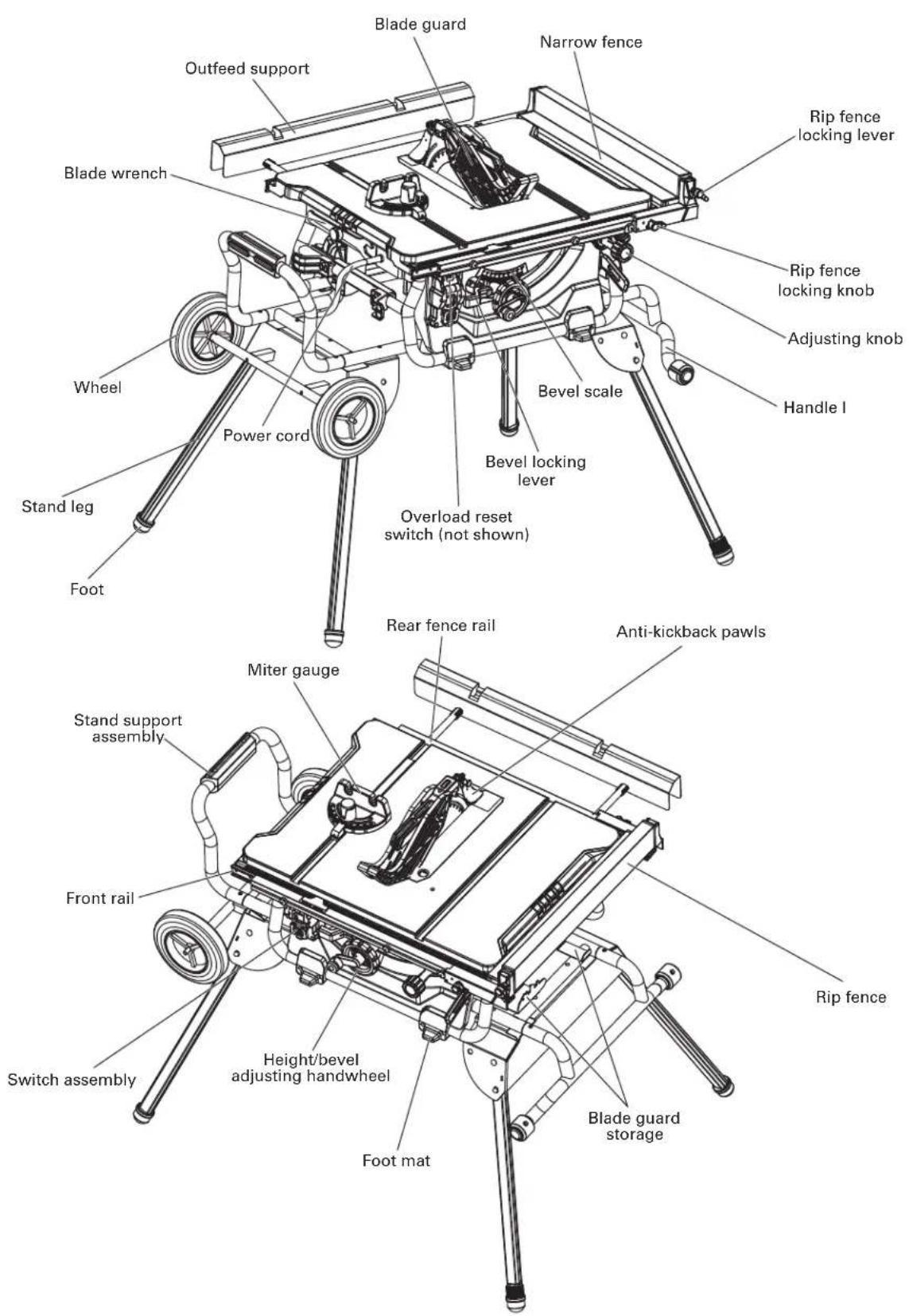
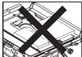
text_image
Blade guard Narrow fence Outfeed support Blade wrench Wheel Power cord Stand leg Foot Blip fence locking lever Rip fence locking knob Adjusting knob Handle I Bevel scale Bevel locking lever Overload reset switch (not shown) Rear fence rail Anti-kickback pawls Miter gauge Stand support assembly Front rail Switch assembly Height/bevel adjusting handwheel Foot mat Blade guard storage Rip fence Rear fence rail Anti-kickback pawls
SPECIFICATIONS
| C 10RJModel |
| 120V~60Hz 15AMotor |
| 4500 RPMNo load speed |
| YesDouble insulated |
| 10" x 5/8" (255mm x 15.9mm) 40T Carbide-tippedBlade |
| 0°~45°Bevel range |
| 28-3/4" x 22" (730mm x 559mm)Working table size |
| 28-3/4" x 2" (730mm x 50mm)Outfeed support size |
| 3-1/8" (79mm)Depth of cut at 0° |
| 2-1/4" (57mm)Depth of cut at 45° |
| 22" (559mm)Max rip to left of blade |
| 35" (889mm)Max rip to right of blade |
| 13/16" (20mm)Max width of dado |
| 96 lbs (44 kg)Weight |
LOOSE PARTS
The following items are included with your table saw:
text_image
Technical diagram showing various mechanical parts with labels A through M, including assembly lines and component layouts.| DESCRIPTIONPART | QUANTITY | |
| A | Table saw assembly | 1 |
| B | Blade guard assembly (in stored position) | 1 |
| C | Anti-kickback pawls assembly (in stored position) | 1 |
| D | Rip fence assembly (in stored position) | 1 |
| E | 1Outfeed support assembly | |
| F | Miter gauge (in stored position) | 1 |
| G | Push stick (in stored position) | 1 |
| H | Blade wrench (in stored position) | 2 |
| I | 1Stand assembly | |
| J | Stand support assembly | 1 |
| K | Handle I assembly | 1 |
| L | Wheel | 2 |
| M | 1Wheel shaft | |
| N | Flat round head screws M8 x 10 | 4 |
| O | Flat round head screws M8 x 45 | 4 |
| P | Flat round head screws M8 x 100 | 2 |
| Q | Locking nut M10 | 2 |
| R | Locking nut M8 | 6 |
| S | Big flat washer 10 | 2 |
| T | 5mm Hex key | 1 |
| U | 14mm Hex key | |
| V | 12.5mm Hex key |
ASSEMBLY
UNPACKING YOUR TABLE SAW
This product requires assembly.
- Carefully lift saw from the carton and place it on a level work surface.
⚠CAUTION: This tool is heavy. To avoid back injury, lift with your legs, not your back, and get help when needed.
- Inspect the tool carefully to make sure that no breakage or damage occurred during shipping.
- Do not discard the packing material until you have carefully inspected and satisfactorily operated the tool.
- The saw is factory set for accurate cutting. After assembling it, check for accuracy. If shipping has influenced the settings, refer to specific procedures explained in this Operator's Manual.
- If any part is missing or damaged, do not attempt to assemble the table saw, plug in the power cord, or turn the switch ON until the missing or damaged part is obtained and is installed correctly.
⚠ WARNING: Remove the protective polyfoam from between the saw's housing and the motor.
⚠ WARNING: The use of attachments or accessories not listed in this manual might be hazardous and could cause serious personal injury.
⚠ WARNING: Do not attempt to modify this tool or create accessories not recommended for use with this tool. Any such alteration or modification is misuse, and could result in a hazardous condition leading to possible serious personal injury.
⚠ WARNING: Do not connect to the power supply until assembly is complete. Failure to comply could result in accidental starting and possible serious personal injury.
⚠ WARNING: Always make sure the table saw is securely mounted to the stand. Failure to heed this warning can result in serious personal injury.
YOU WILL NEED
| ITEMS NOT SUPPLIED | ITEMS SUPPLIED |
| Flat head screwdriver | Blade wrench (2 pc) |
| Screwdriver | 2.5mm Hex key (1 pc) |
| 13mm wrench / Adjustment wrench | 4mm Hex key (1 pc) |
| Framing square | 5mm Hex key (1 pc) |
| Triangle square |
⚠ WARNING: To avoid injury, do not connect this table saw to a power source until it is completely assembled and adjusted and you have read and understood the operator's manual.
⚠CAUTION: Many of the illustrations in this manual show only portions of the table saw. This is intentional so that we can clearly show points being made in the illustrations. Never operate the saw without all guards securely in place and in good operating condition.
ASSEMBLE THE STAND (Fig. 2a-2e)
- Place cardboard or an old blanket on floor in order to protect the surface of the working table.
- Place the table saw assembly (A) upside down on the protective material.
- Attach the stand assembly (B) to the table saw assembly (A) with four flat round head screws M8 x 45 (C) and four locking nut M8 (D)(two holes on the side board of the stand assembly located on the blade wrench storage). (Fig. 2a)
- Attach the tubes of the stand support assembly (E) with the corresponding tubes (located on side of blade wrench storage) on the stand assembly (B) and align the holes. Insert the flat round head screws M8 x 10 (F) into the hole and tighten with 5mm hex key. (Fig. 2b)
- Slide one wheel (G), one big flat washer 10 (H) and one locking nut M10 (I) onto the wheel shaft (J), secure wheel in place by tightening the locking nut M10. Repeat with the second wheel. (Fig. 2c)
- Attach the wheel assembly (K) to the stand assembly (B) with two flat round head screws M8 x 100 (L) and two locking nut M8 (D). (Fig. 2d)
- Attach the tubes of the handle I assembly (M) with the corresponding tubes (located on side of blade guard storage) on the stand assembly (B) and align the holes. Insert the flat round head screws M8 x 10 (F) into the hole and tighten with 5mm hex key. (Fig. 2e)

OPEN THE STAND (Fig. 3a-3d)
- Grasp the handle I (A) and tilt saw back onto wheels until the stand is balanced on the wheels (B) and stand support assembly (C). (Fig. 3a)
- Fold out two lower stand legs (D) (located on side of the wheel). To do this, push the locking pins (E) until they unlock the stand legs (D) from the holes, then swing the stand legs (D) upward until the stand legs (D) are locked with the locking pins (E) engage the holes. (Fig. 3a)
- Grasp the handle I (A) firmly and slowly tilt saw to you until the saw is balanced on the ground. (Fig. 3b-3c)
- Grasp the stand support assembly (F) and lift it up until two other stand legs (G) leaving off the ground, then fold out two stand legs (G). To do this, push the lock pins (H) until they unlock the stand legs (G) from the holes, then swing the stand legs (G) downward until the stand legs are locked with the locking pins (H) engage the holes. (Fig. 3c) Make sure the table saw is balanced with four leg stands stand on the floor.
- Fig. 3d is the leg stand assembly in an open position.
⚠ WARNING: Keep your fingers clear of the hinge points while opening the stand. Danger of fingers being crushed or contused.

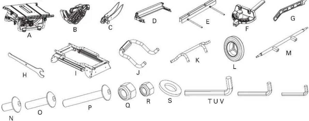
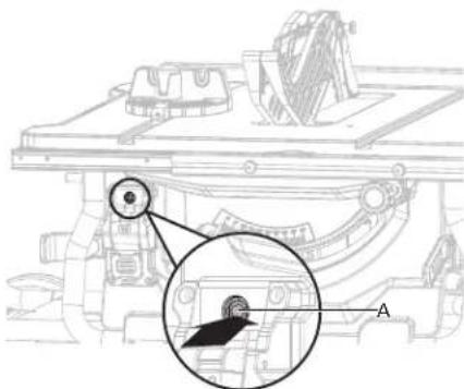
TO SECURE/LEVEL THE STAND (Fig. 4)
With the stand open, resting on a level surface, the stand should not move or rock from side to side. If the stand rocks from side to side, the adjustable foot (A) need adjusting until the stand is balanced.
natural_image
Technical line drawing of a robotic device with an inset showing a test probe and rotating component (no text or symbols)Fig. 4
- Lift the stand slightly so that you may turn the adjustable foot (A) until the stand no longer rocks.
- Turning clockwise will lower the foot.
- Turning counter-clockwise will raise the foot.
WARNING: The table saw must be secured. A table saw that is not properly secured may move or tip over.
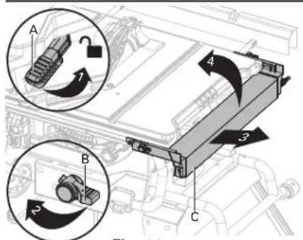
TO REMOVE/REPLACE/ALIGN THE TABLE INSERT (Fig. 5a-5b)
⚠ WARNING: The table insert must be level with the saw table. If the table insert is too high or too low, the workpiece can catch on the uneven edges, resulting in binding or kickback, which could result in serious personal injury.
⚠ WARNING: Be care of your hands avoided to be spiked with the saw blade which could result in serious personal injury when removing or reinstalling the table insert.
- Lower the blade all the way to down position by turning the height adjusting knob (A) counter-clockwise.
- Lock the blade by turning bevel-lock lever (B) clockwise.
- To remove the table insert: Place your index finger in the hole and push the locking tab (D) front, pulling the table insert (C) out toward the front of the saw.
- To reinstall the table insert: Push the locking tab (D) front, and at the same time push the table insert (C) down to secure in place.
When the table insert is not level with the saw table, using a 2.5mm hex key (not supplied), adjust the four set screws (E) pre-assembled to the table located under the table insert until the table insert is level with the saw table.
text_image
Technical diagram of a mechanical assembly with labeled components A, B, C, and D, showing internal components and assembly details.Fig. 5a

text_image
EFig. 5b
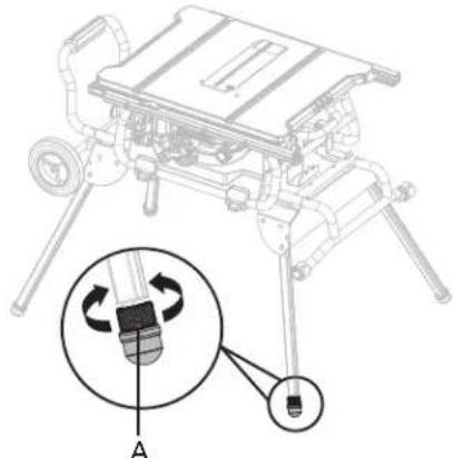
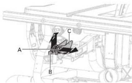
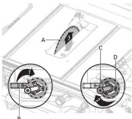
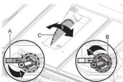
RIVING KNIFE INSTALLATION AND POSITION (Fig.6a-6c)
⚠CAUTION: This saw is shipped with riving kinfe in "DOWN" position. Riving kinfe must be placed in uppermost position to attach anti-kickback pawls and blade guard for all through cut operations.
text_image
D CIn uppermost position for through cuts
Through cutting riving kinfe installation and position
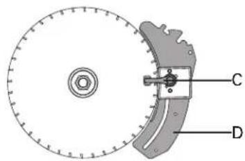
⚠WARNING: Riving knife has three holes for three positions. The uppermost position is for all through cuts. The middle position is for non-through cuts (with blade guard and anti-kickback pawls removed). The down position is for dado cuts. (with blade guard and anti-kickback pawls removed).
- Unplug the saw.
To place riving knife in uppermost position (for through cuts)
- Remove the table insert.
- Set the saw blade angle to 0^ .
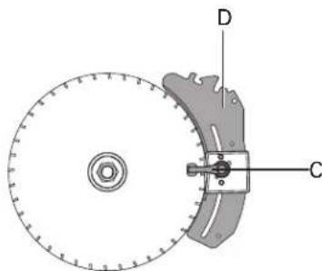
text_image
Technical diagram of a mechanical assembly with labeled components D and CIn middle position for non-through cuts
- Raise the saw blade to the uppermost positon by turning the height adjusting knob (A) clockwise.
- Lock the blade by turning bevel-lock lever (B) clockwise.
- Unlock riving knife lock knob (C) by turning it clockwise.
- Grasp the riving knife (D) and pull toward right side of saw to release it from spring-loaded locking pin.
- Position the riving knife in the uppermost position with spring-loaded locking pin is re-engaged.
- Lock the riving knife lock knob (C) by turning it counter-clockwise.
- Reinstall the table insert.
⚠WARNING: Be extremely careful when adjust the riving knife position. Do not allow hands to contact blade.
text_image
Technical diagram of a mechanical component with labeled parts C and DIn down position for dado cuts
To place riving knife in middel or down position, refer to the above procedure.
Fig. 6a

text_image
A D BFig. 6b

text_image
D CFig. 6c
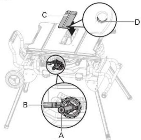
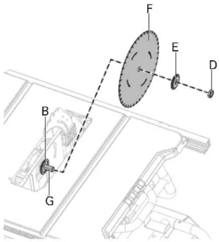
REMOVING AND INSTALLING THE BLADE (Fig. 7a-7b)
⚠CAUTION: To work properly, the saw blade teeth must point down toward the front of the saw. Failure to heed this instruction could cause damage to the saw blade, the saw or the workpiece.
⚠ WARNING: Make sure that the saw blade is installed to rotate in the proper direction. Do not use grinding wheels, wire brushes, or abrasive wheels on a table saw. Improper saw blade installation or use of accessories not recommended may cause serious injury.
⚠ WARNING: Only use a 10 in. diameter blade. To avoid injury from an accidental start, make sure the switch is in the OFF position and the plug is not connected to the power source outlet.
text_image
A C F DFig. 7a
text_image
Technical diagram showing labeled components (A, B, C, D, E, F, G) of a mechanical assembly with dashed lines indicating connections.Fig. 7b
- Unplug the saw.
- Turn height-adjustment knob clockwise to raise blade to maximum height.
- Remove the table insert.
- Remove the blade wrenches from storage area.
Remove the blade:
- Using one opened-ended blade wrench (A), place the flat open end on the flats on the inner blade flange (B).
- Using the other opened-ended blade wrench (C), place the flat open end on the flats on the arbor nut (D). Holding both wrenches firmly, pull the opened-ended blade wrench on the arbor nut (D) forward to the front of the machine.
- Remove arbour nut (D), outer blade flange (E) and saw blade (F).
⚠ WARNING: Be extremely careful when loosening arbour nut. Keep firm grasp on both wrenches. Do not allow hands to slip and contact blade.
Install the blade:
- Place one new blade on arbour (G). Make sure saw blade teeth point down at the front side of saw table. Place outer flange (E) and nut (D) on arbour and use blade wrenches to tighten nut securely. DO NOT over tighten.
⚠ WARNING: The large, flat surface of the outer flange faces the the saw blade and the saw blade (F) is firmly seated against the inner flange (B).
- Lower the saw blade to lowest position and replace table insert.
⚠ WARNING: If the inner flange has been removed, reinstall it before placing the saw blade on arbor. Failure to do so could cause an accident.
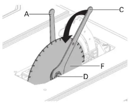
ANTI-KICKBACK PAWLS AND BLADE GUARD INSTALLATION (Fig. 8a-8b)
Anti-kickback pawls should only be installed for through cuts.
⚠WARNING: Make sure the anti-kickback pawls are reinstalled immediately after finishing any non-through cut operations which require their removal.
⚠ WARNING: Replace dull or damaged anti-kickback pawls. Dull or damaged anti-kickback pawls may not stop a kickback, increasing the risk of serious personal injury.
text_image
A B CFig. 8a
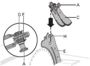
text_image
G F A A C H D EFig. 8b
- Unplug the saw.
- Set the blade angle to 0^ .
- Raise the saw blade to maximum height by turning height adjustment knob clockwise.
- Lock the blade by turning bevel-lock lever clockwise.
- Place the riving knife in the highest position.
- Pull out and hold knob (A) and push anti-kickback pawls up, remove it from the anti-backpawls storage (B) located on inside of the left side of saw. (Fig. 8a)
- Pull out and hold knob (A). Align slot in anti-kickback pawls (C) over the slot (D) indicated of riving knife (E). Place the spring pin (F) on the anti-kickback pawls (C) into the slot (D) indicated on the riving knife (E).
- Press anti-kickback pawls (C) down until it snaps into place and release knob (A) to insert the pin (G) into hole (H) indicated on the riving knife (E).
⚠CAUTION: Pull up on anti-kickback pawl assembly to make sure it is secured to riving knife.
⚠WARNING: Use extra caution when cutting wood products having slippery surface as the anti-kickback pawls may not always be effective.
BLADE GUARD INSTALLATION (Fig. 9a-9c)

text_image
A B C F 1 2Fig. 9a
⚠ WARNING: KEEP GUARDS IN PLACE
and in good working order for all through cut operations. Reinstall the blade guard immediately after finishing any non-through cut operations

natural_image
Pure mechanical assembly diagram without any text, numbers, or symbolswhich require removal of the blade guard. Failure to heed this instruction could result in serious personal injury.
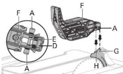
text_image
F A E D A F A G HFig. 9b
- Unplug the saw.
- Hold the knobs (A) (one on either side of the blade guard) and push the knobs forward to the front of the blade guard and up until the pin comes out from the slot in the mounting bracket (blade guard storage) (B) at bottom front right side of the saw, then remove the blade guard from the U-bracket (blade guard storage) (C) at bottom middle right side of the saw (Fig. 9a).
- Hold and push knobs (A) forward to the front of the blade guard. Place the pins (D, E) on the blade guard (F) into the slots (G, H) indicated on the riving knife. (Fig. 9b)
- Pull blade guard fully back onto riving knife. Push pin and release it to lock guard into position.
- If blade guard is not parallel to table when riving knife is in uppermost position (through cuts), adjust the set screw (I) as necessary. (Fig. 9c)

text_image
I FFig. 9c
⚠WARNING: After the installation, check the blade guard to ensure that it is properly placed and workable before operation the saw.
OUTFEED SUPPORT ASSEMBLY INSTALLATION (Fig. 10a-10b)

text_image
A B C BFig. 10a

text_image
Fig. 10b A 2 3 4 5 6 7 8 9 10 11 12 13 14 15 D C- Loosen two stop screws (A) on the extension poles (B) of the outfeed support (C).
- Loosen the locking knobs (D) under the working table counterclockwise.
- Insert the rear extension table poles (B) into the two holes in the rear of the work table and into the extension tube brackets that are located under the work table. Position the outfeed support.
- Thread the locking knobs (D) into the the holes under the work table and tighten them.
- Thread the two stop screws (A) into the holes located on ends of the extension poles (B) and tighten them.
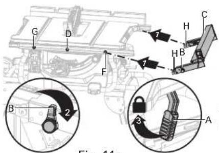
RIP FENCE INSTALLATION (FIG. 11a-11c)
text_image
A B C 4 3 2 Fig. 11Fig. 11a

text_image
G E F D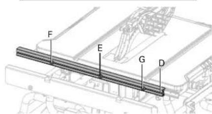
text_image
F E G DFig. 11b
- Push down the fence rails lever (A) toward the rear of the saw to unlock it.
- Loosen the rip fence locking knobs (B) on the rip fence.
- Sliding the rip fence (C) to right and swing it up at an angle, then remove the fence from the front and rear fence rails (D).
⚠CAUTION: There are three position screws (E, F, G) on the each front and rear fence rails (D) to attach rip fence. Position screws (E, F) use for rip fence on the right of saw blade. Position screws (G) use for rip fence on the left of saw blade. (Fig. 11b)
- Holding the fence (C) at an angle, align the position screws (front and back) on fence rails with the fence slots (H).
- Slide the slots (H) onto the position screws and rotate the fence down until it rests on the rails.
- Secure the rip fence in place by turning the rip fence locking knobs (B) clockwise.
- Lock the fence rails lever (A).
CAUTION: The rip fence should be parallel to the saw blade. If not, refer to the section "ALIGNING RIP FENCE TO BLADE".
CAUTION: Three position screws apply to three different scales: Position screw AA: Begin with 0 to 27 in. end. (Rip fence located on the right of the blade)
text_image
G D F B 2 3 A H C 7 7 Fig. 11aFig. 11c
Position screw BB: Begin with 8 in. to 35 in. end. (Rip fence located on the right of the blade) Position screw CC: Begin with 0 to 22 in. end. (Rip fence located on the left of the blade)
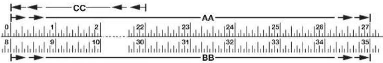
text_image
CC AA BBMITER GAUGE INSTALLATION (FIG. 12a-12b)
The miter gauge (A) can be installed on each miter gauge groove (B) on either side of blade.
- Remove the miter gauge (A) from storage area (C) located on inside of the right side of saw).
- Slide the guide rail (D) of the miter gauge (A) into one of the guide grooves (B) of the saw table intended for this purpose.
text_image
Technical diagram of a mechanical assembly with labeled components A, C, and directional arrows indicating flow or movement.Fig. 12a Fig. 12b
text_image
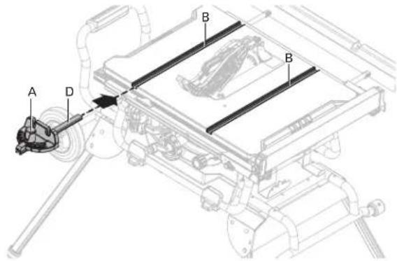
Technical diagram of a mechanical assembly with labeled components A, B, and DTO STORE THE TABLE SAW ACCESSORIES (Fig. 13a-13c)
- The table saw has two convenient storage areas (one on either side of the saw) specifically designed for the saw's accessories: rip fence assembly (A), blade guard assembly (B), push stick (C), blade wrenches (D), plug cable (E), anti-kickback pawls (F) and miter gauge (G).
- When not in use, store accessories securely.

text_image
Technical diagram of a vehicle engine compartment with labeled parts A, B, and Ctext_image
F C D EA A G
text_image
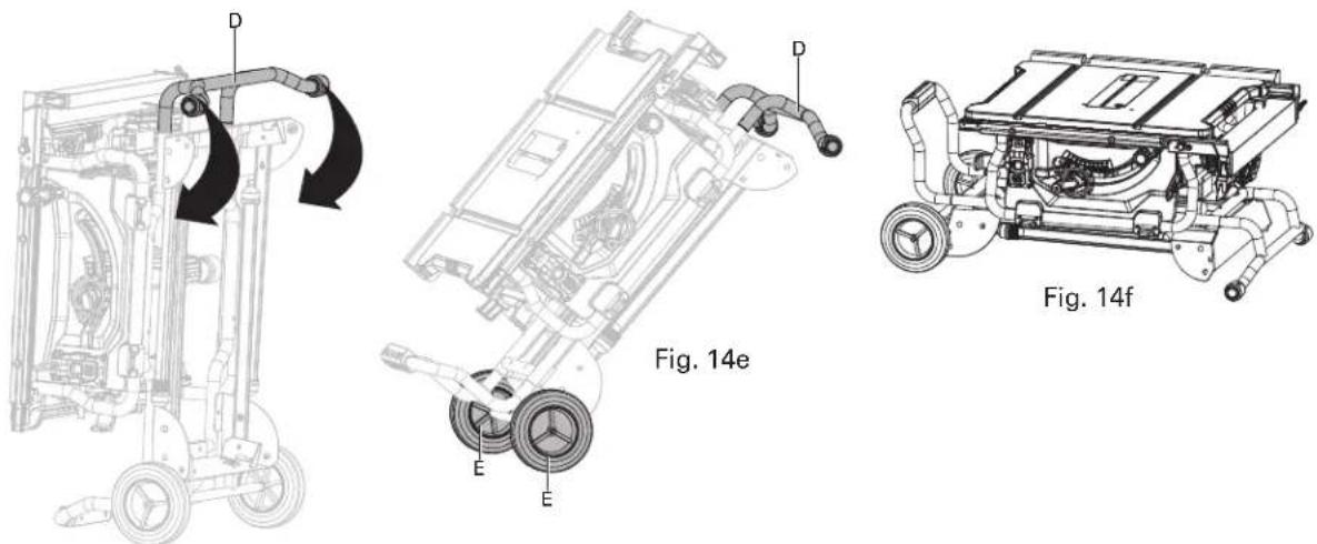
A C B F GFOLDING THE STAND (Fig. 14a-14f)
- To fold the stand for moving, return fence rails and outfeed support to inner position. Store the accessories securely.
- Grasp the stand support assembly (A) and lift it up until two stand legs (B) (located on side of the wheel) leaving off the ground, then fold in two stand legs (B). To do this, push the lock pins (C) until they unlock the stand legs (B) from the holes, then swing the stand legs (B) upward until the stand legs are locked with the locking pins (C) engage the holes.
- Grasp the handle I (D) and tilt saw back onto wheels until the stand is balanced on the wheels (E) and stand support assembly (A). (Fig. 14b-14c)
- Fold in other two stand legs (F). To do this, push the locking pins (G) until they unlock the stand legs (F) from holes, then swing the stand legs downward until the stand legs are locked with the locking pins (G) engage the holes.
- Grasp the handle I (D) firmly and tilt saw to you, push the saw to the desired location (Fig. 14e) then either open the stand or store the saw (Fig. 14d & 14f) in a dry environment.
⚠ WARNING: Keep your fingers clear of the hinge points while folding the stand. Danger of fingers being crushed or contused.

text_image
Fig. 14b Fig. 14cFig. 14a
text_image
D D E E Fig. 14e Fig. 14fFig. 14d
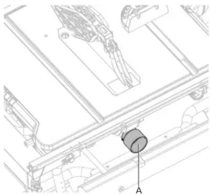
CONNECT TO A DUST COLLECTION SYSTEM (Fig. 15)
natural_image
Technical line drawing of a mechanical assembly with labeled component A (no text or symbols beyond label)Fig. 15
The dust extraction port (A) with 2 1/2" (6.35 cm) size is located on the back of the table saw. This port can be connected directly to a dust collection system by connecting the pick up end of the dust collection hose to the dust port.
⚠ WARNING: ALWAYS connect to a dust collection system and the table saw must be regularly checked for dust built up and cleaned frequently, otherwise there is a risk of heat built up and potential fire.
OPERATION
△DANGER: Feed the workpiece into the saw blade or cutter only against the direction of rotation. Feeding the workpiece in the same direction that the saw blade is rotating above the table may result in the workpiece, and your hand, being pulled into the saw blade.
⚠WARNING: In the event of a power failure or when the tool is not in use, turn the switch OFF. This action will prevent the tool from accidentally starting when power returns.
⚠WARNING: ALWAYS make sure your workpiece is not in contact with the blade before operating the switch to start the saw. Blade contact could result in kickback or thrown workpiece.
⚠WARNING: To reduce the risk of accidental starting, ALWAYS make sure the switch is in the OFF position before plugging saw into the power source.
⚠ WARNING: DO NOT use blades rated less than the speed of this tool. Failure to heed this warning could result in serious personal injury.
WARNING: The operation of any power tool can result in foreign objects being thrown into the eyes, which can result in severe eye damage. Always wear safety goggles or standard safety glasses with side shields complying with United States ANSI Z87.1 before commencing power tool operation.
⚠WARNING: Never operate the saw with the blade guard removed except for dado and other non-through cuts. Reinstall the blade guard immediately after finishing any non-through cut operations which require removal of the blade guard. Failure to heed this instruction could result in serious personal injury.
natural_image
Pure mechanical assembly diagram without any text, numbers, or symbolsOPERATING COMPONENTS
- The upper portion of the blade projects up through the table and is surrounded by an insert called the table insert. The height of the blade is set with a height adjusting handle on the height/bevel adjusting handwheel. Detailed instructions are provided in this manual for the basic cut: cross cuts, miter cuts, bevel cuts, and compound cuts.
- The rip fence is used to position workpiece for lengthwise cuts and used for extension table for large workpiece cuts.
- It's very important to use the blade guard assembly for all through-cut sawing operations. The blade guard assembly includes: riving knife, anti-kickback pawls, and blade guard.
CAUSES OF KICKBACK
Kickback can occur when the blade stalls or binds, causing the workpiece to be kicked back toward the operator with great force and speed. If your hands are near the saw blade, they may be jerked loose from the workpiece and come into contact with the blade. Obviously, kickback can cause serious injury, and it is well worth using precautions to avoid the risks. Kickback can be caused by any action that pinches the blade in the wood, such as the following:
- Making a cut with incorrect blade depth.
- Sawing into knots or nails in the work piece.
- Twisting the wood while making a cut.
- Failing to support the workpiece.
- Forcing a cut.
- Cutting warped or wet lumber.
- Using the wrong blade for the type of cut.
- Not following correct operating procedures.
-
Misusing the saw.
-
Failing to use the anti-kickback pawls.
- Cutting with a dull, gummed-up, or improperly set blade.
PRECAUTIONS OF KICKBACK
NOTE: Kickback can be avoided by taking following proper precautions:
- Never stand directly in line with the saw blade. Always position your body on the same side of the saw blade as the fence. Kickback may propel the workpiece at high velocity towards anyone standing in front and in line with the saw blade.
- Never reach over or in back of the saw blade to pull or to support the workpiece. Accidental contact with the saw blade may occur or kickback may drag your fingers into the saw blade.
- Never hold and press the workpiece that is being cut off against the rotating saw blade. Pressing the workpiece being cut off against the saw blade will create a binding condition and kickback.
- Align the fence to be parallel with the saw blade. A misaligned fence will pinch the workpiece against the saw blade and create kickback.
- Use a featherboard to guide the workpiece against the table and fence when making non-through cuts such as rabbets, dado cuts. A featherboard helps to control the workpiece in the event of a kickback.
- Use extra caution when making a cut into blind areas of assembled workpieces. The protruding saw blade may cut objects that can cause kickback.
- Support large panels to minimise the risk of saw blade pinching and kickback. Large panels tend to sag under their own weight. Support(s) must be placed under all portions of the panel overhanging the table top.
- Use extra caution when cutting a workpiece that is twisted, knotted, warped or does not have a straight edge to guide it with a miter gauge or along the fence. A warped, knotted, or twisted workpiece is unstable and causes misalignment of the kerf with the saw blade, binding and kickback.
- Never cut more than one workpiece, stacked vertically or horizontally. The saw blade could pick up one or more pieces and cause kickback.
- When restarting the saw with the saw blade in the workpiece, center the saw blade in the kerf so that the saw teeth are not engaged in the material. If the saw blade binds, it may lift up the workpiece and cause kickback when the saw is restarted.
- Keep saw blades clean, sharp, and with sufficient set. Never use warped saw blades or saw blades with cracked or broken teeth. Sharp and properly set saw blades minimise binding, stalling and kickback.
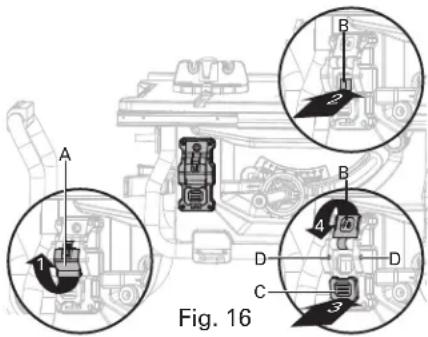
SWITCH ASSEMBLY (FIG. 16)
⚠ WARNING: To reduce the risk of injury, be sure switch is in the OFF position before plugging machine in.
text_image
Fig. 16To turn saw on and off:
- Flip the switch cover (A) upward.
- Press the switch I (B) to turn on the saw.
- Press the switch paddle (C) to turn off the saw.
To lock saw:
- Flip the switch cover (A) downward.
- The holes (D) is provided in the switch for insertion of a padlock with a removable shank to lock the saw off.
⚠️NOTE: A conventional padlock will not fit.
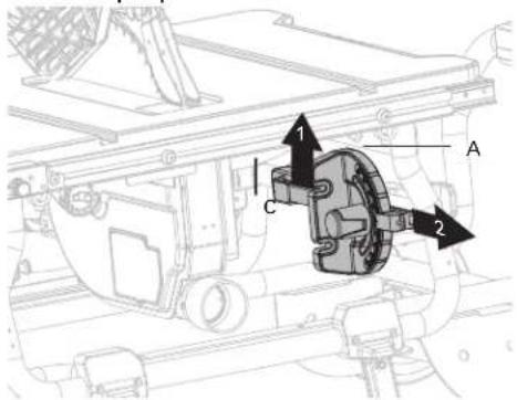
OVERLOAD PROTECTION (FIG. 17)
natural_image
Technical line drawing of a mechanical assembly with a magnified inset showing a component labeled 'A' (no text or symbols present)Fig. 17
The saw is equipped with an overload switch (A) to prevent the saw from overload damage. The saw will stop if the machine was overloaded with cutting or low voltage. Turn the switch to the OFF position and allow the motor to cool down for at least five minutes. Press the overload switch button to reactivate the overload switch. After the motor has cooled down, turn the switch to the ON position. The saw should now start.
CHANGING BLADE DEPTH (FIG. 18)
Blade depth should be set so that outer points of blade (A) are higher than workpiece by approximately 1/8 in. to 1/4 in. and bottom of gullets are below top surface of workpiece.
text_image
A 3 1 B C DFig. 18
- Turn the bevel locking lever (B) clockwise to tighten it securely.
- Raise blade (A) by turning height adjusting handle (C) on the height/bevel adjusting handwheel (D) clockwise. Lower blade by turning height adjusting handle (C) counter-clockwise.
- Make sure blade (A) is at proper height.
⚠ WARNING: Make sure the blade guard is in place after adjusting the blade depth. Failure to heed this instruction could result in serious personal injury.
CHANGING BLADE ANGLE (BEVEL) (FIG. 19)
⚠CAUTION: A 90° cut has a 0° bevel and a 45° cut has a 45° bevel.
CAUTION: If bevel indicator is not at zero when saw blade is at 0°, see the section "ADJUSTING BEVEL INDICATOR".
text_image
A C B 1 2Fig. 19
- Loosen the bevel locking lever (A) counter-clockwise.
- Adjust bevel angle by first pushing height/bevel adjusting handwheel (B) all the way to the left.
- Holding height/bevel adjusting handwheel, slide bevel indicator to the right to increase angle of blade (C) (bringing it closer to 45^ from the tabletop). Holding height/bevel adjusting handwheel, slide bevel indicator to the left to decreases the angle (bringing blade closer to 90^ from the tabletop).
- Make sure blade (C) is at desired angle. Tighten bevel locking lever (A) clockwise.
WARNING: Make sure the blade guard is in place after adjusting blade angle. Failure to heed this instruction could result in serious personal injury.
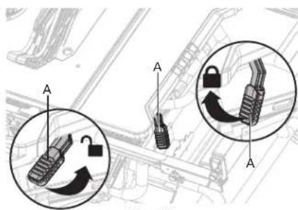
RIP FENCE (FIG. 20a-20c)

WARNING: To reduce the risk of injury, always make sure the rip fence is parallel to the blade before beginning any operation.
text_image
Diagram showing mechanical components with labeled parts A and directional arrows indicating motion or movement.Fig. 20a
text_image
Fig. 20a C B
text_image
Technical diagram showing mechanical assembly with labeled components and a magnified inset highlighting a lock mechanism.Fig. 20b

text_image
F BD F 2 2 E Fig. 20cFENCE RAILS LOCKING LEVER (Fig. 20a)
The fence rails locking lever locks the rip fence in place preventing movement during cutting.
- To lock the fence rails locking lever (A), push it up and toward the front of the saw.
- To unlock the fence rails locking lever (A), push it down and toward the rear of the saw.

CAUTION: When ripping, always lock the fence rails locking lever.
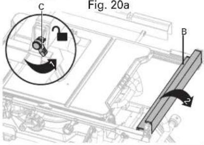
NARROW FENCE (Fig. 20b)
Your table saw is equipped with a narrow fence (B) to support workpiece that extends beyond the working table.
- To use the narrow fence (B), turn the locking lever (C) clockwise and rotate the narrow fence (B) as shown in Fig. 20b, then turn the locking lever (C) counter-clockwise to to lock.
- When not in use, turn the locking lever (C) clockwise and retracts the narrow fence (B) as shown in Fig. 20b.
ADJUSTMENT KNOB (Fig. 20c)
The adjustment knob allows smaller adjustments when setting the rip fence.
- Unlock the fence rails locking lever (A).
- Slide the rip fence (D) close to the desired position.
- Slowly turn the adjustment knob (E) to set the rip fence to desired position. Turn the adjustment knob clockwise will extend the fence rails (F) to right. Turn the adjustment knob counter-clockwise will extend the fence rails (F) to left.
- Lock the fence rails locking lever (A).
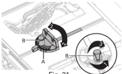
MITER GAUGE (FIG. 21)
The miter gauge (A) provides accuracy in angled cuts. For very close tolerances, test cut are recommended.
There are two miter gauge grooves, one on either side of blade. When making a 90^ cross cut, use either miter gauge groove. When making a beveled cross cut (blade tilted in relation to working table, miter gauge should be located in groove on right so that blade is tilted away from miter gauge and hands.
text_image
B A 2 2 B 3 1 Fig. 21Fig. 21
- Using miter gauge
- Loosen lock knob (B) turning it counter-clockwise.
- With miter gauge in miter gauge groove, rotate gauge until desired angle on scale is reached.
- Retighten lock knob (B) turning it clockwise.
OUTFEED SUPPORT (FIG. 22)
The outfeed support (A) slides to give operator additional support for cutting long workpieces.

text_image
A 2 1 B 3 B Fig. 22Fig. 22
- Unplug the saw.
- Loosen the locking knobs (B) under the working table counterclockwise.
- Stand behind saw. Grasp outfeed support (A) with both hands and pull until it is fully extended.
- Tighten the locking knobs (B) clockwise.
CUTTING AIDS
Cutting aids such as push stick, push blocks, featherboards and jigs should be used where appropriate to maximize your ability to control your workpiece for a safe and precise cut. When making non-through cuts or ripping narrow stock, always use a push stick, push block, featherboard and/or jig set-up so hands do not come within 6 inches of blade.
A push stick is included with your saw. Additional push sticks and other cutting aids can be purchased separately at any authorized dealer. Instructions for making cutting aids can be found at on page 33-35.
PUSH STICKS
Push stick can be purchased or made to securely hold down the workpiece against the table when making non-through cuts or ripping narrow stock. The stick must be narrower than the workpiece, with a 90^ notch in one end and shaped for a grip on the other end.
⚠ WARNING: Use only the push stick provided by the manufacturer or constructed in accordance with the instructions. This push stick provides sufficient distance of the hand from the saw blade.
⚠ WARNING: Never use a damaged or cut push stick. A damaged push stick may break causing your hand to slip into the saw blade.
FEATHERBOARDS
A featherboard is a device used to help control the workpiece by guiding it securely against the table or rip fence. Featherboards are especially useful when ripping small workpieces and for completing non-through cuts. The end is angled with a series of narrow slots to give a friction hold on the workpiece. It is locked in place on the table with a C-clamp.
PUSH BLOCKS
Push blocks are blocks used to securely hold down the workpiece against the table. They include some gripping surface or handle to hold the block. Any screws running through the underside of the block to fasten the handle should be recessed in order to avoid contact with the workpiece.

WARNING: When using featherboard, it must be mounted in front of the blade and used only against the uncut portion of the workpiece to avoid a kickback that could result in serious injury.
HOW TO MAKE AN ADDITIONAL PUSH STICK (FIG. 23a-23b)
- In order to operate your table saw safely, you must use a push stick whenever the size or shape of the workpiece would otherwise cause your hands to be within 6 in. (152 mm) of the saw blade or other cutter. A push stick is included with this saw.
- No special wood is needed to make additional push-sticks as long as it's sturdy and long enough. A length of 15.7 in. (400 mm) is recommended with a notch that fits against the edge of the workpiece to prevent slipping. It's a good idea to have several push sticks of the same length 15.7 in. (400 mm) with different size notches for different workpiece thicknesses.
- The shape can vary to suit your own needs as long as it performs its intended function of keeping your hands away from the blade.

text_image
Included standard push stickFig. 23a
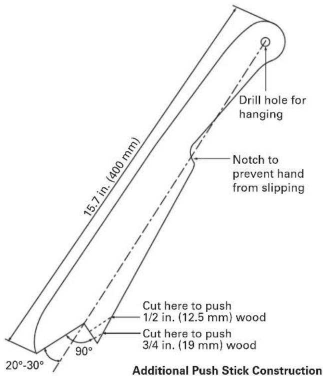
text_image
Drill hole for hanging Notch to prevent hand from slipping 15.7 in. (400 mm) Cut here to push 1/2 in. (12.5 mm) wood Cut here to push 3/4 in. (19 mm) wood 20°-30° 90° Additional Push Stick ConstructionFig. 23b
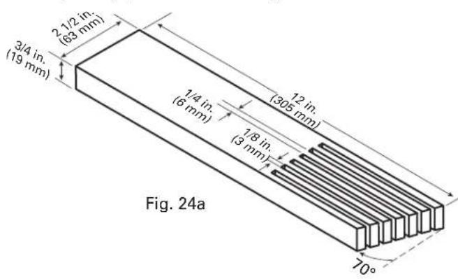
HOW TO MAKE A FEATHERBOARD (FIG. 24a-24b)
- Select a solid piece of lumber approximate 3/4 in. (19 mm) thick, 2 1/2 in. (63 mm) wide and 12 in. (305 mm) long.
- Mark the center width on one end of stock. Miter width to 70^ (See miter cut section for information on miter cuts).
- Set rip fence to allow approximately a 1/4 in. (6 mm) "finger" to be cut in the stock.
- Feed stock only to mark previously a 1/4 in. (6 mm) "finger" to be cut in the stock.
- Turn saw off and allow blade to completely stop rotating before removing stock.
- Reset rip fence and cut spaced rips into workpiece to allow approximately 1/4 in. (6 mm) fingers and 1/8 in. (3 mm) spaces between fingers.
text_image
2.1/2 in. (63 mm) 3/4 in. (19 mm) 1/4 in. (6 mm) 1/8 in. (3 mm) 12 in. (305 mm) Fig. 24a 70°
natural_image
Technical line drawing of a machine tool with rollers and conveyor (no text or symbols)Fig. 24b
HOW TO MAKE A PUSH BLOCK (FIG. 25a-25b)
- Select a piece of wood about 4 in. (101 mm) wide, 6 in. (152 mm) long and 1 (25 mm) to 2 in. (51 mm) thick (a cutoff from a 2 in. (51 mm) by 4 in. (101 mm) makes a good blank for a push block).
- Drill a hole in the block and glue in a dowel to use as a handle (you can angle the hole to provide a more comfortable grip on the handle).
- To finish off the block, glue a piece of sandpaper or some kind of rubber material (old mouse pads work well) to the bottom of the block.

text_image
4 in. (101 mm) 6 in. (152 mm) Wooden dowel 2 in. (51 mm) Sandpaper or old mouse pad material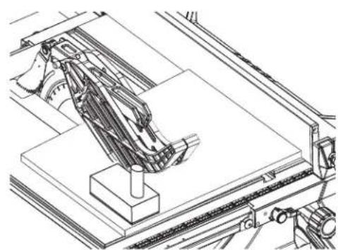
natural_image
Technical line drawing of a mechanical assembly with no visible text or symbolsFig. 25b
Fig. 25a
⚠ WARNING: Use a push block when the distance between the fence and the saw blade is less than 2 in. (51 mm).
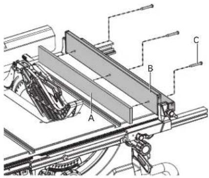
HOW TO MAKE AN AUXILIARY FENCE (FIG. 26)
An auxiliary fence is a device used to close the gap between rip fence and working table. ALWAYS use an auxiliary fence when ripping material 1/8 in. (3 mm) or thinner to prevent stock from slipping under fence.
text_image
Technical diagram of a mechanical assembly with labeled components A, B, and CFig. 26
- Select a piece of wood 3/4 in. (19 mm) thick, 2 3/8 in. (60 mm) wide and as long as the rip fence.
- Drill a 1/4 in. (6 mm) hole, 1 in. (25 mm) from each end of the narrow fence.
- Drill a 1/4 in. (6 mm) hole in the middle rip fence 1/2 in. (12.5 mm) from bottom of auxiliary fence.
- Attach auxiliary fence (A) to the narrow fence (B); place wood against narrow fence and firmly on the working table.
- From back side of rip fence, secure wood to fence using wood screws (C) (not included).
⚠CAUTION: Make sure hardware does not protrude from front of auxiliary wood fence.
THROUGH CUTS
⚠ WARNING: Always make sure the blade guard and anti-kickback pawls are in place and working properly when making these cuts to avoid possible injury.
⚠ WARNING: Use extra caution when cutting wood products having slippery surface as the anti-kickback pawls may not always be effective.
⚠ WARNING: DO NOT use blades rated less than the speed of this tool. Failure to heed this warning could result in personal injury.
⚠ WARNING: To avoid kickback, make sure one side of the workpiece is securely against the rip fence during any rip cut, and hold the workpiece firmly against the miter gauge during any miter cut.
⚠ WARNING: DO NOT attempt compound miter cuts, with blade beveled and miter fence angled, until you are thoroughly familiar with the basic cuts and understand how to avoid kickback.
⚠ WARNING: DO NOT attempt to make any cuts not covered here.
⚠ WARNING: Using rip fence as a cutoff gauge when cross cutting will result in kickback which can cause serious personal injury.
⚠ WARNING: NEVER make freehand cuts (cuts without miter gauge or rip fence). Unguided workpieces can result in serious injury.
⚠ WARNING: Never make through cuts without the blade guard in place. Failure to heed this instruction could result in serious personal injury.

natural_image
Pure mechanical assembly diagram without any text, numbers, or symbolsCUTTING TIPS
- The kerf (the cut made by the blade in the wood) will be wider than the blade to avoid overheating or binding. Make allowance for the kerf when measuring wood.
- Make sure the kerf is made on the waste side of the measuring line.
- Cut the wood with the finish side up.
- Knock out loose knots before making cut.
• Always provide proper support for wood as it comes out of saw.
MAKING CUTS
- Stand slightly to the side of blade path to reduce the chance of injury should kickback occur.
- Use miter gauge when making cross, miter, bevel and compound miter cuts. To secure angle, lock miter guage in place by twisting lock knob clockwise. ALWAYS tighten lock knob securely in place before use.
WARNING: Never use the fence and miter gauge together. This may cause a kickback condition and injury to the operator.
TYPES OF CUTS (FIG. 27)
There are six basic cuts: 1) the cross cut, 2) the rip cut, 3) the miter cut, 4) the bevel cross cut, 5) the bevel rip cut, and 6) the compound (bevel) miter cut.
⚠CAUTION: All other cuts are combinations of these basic six. Operating procedures for making each kind of cut are given later in this section.

text_image
Cross cut Rip cut Miter cut Bevel cross cut Bevel rip cut Compound (bevel) miter cutFig. 27
MAKING A CROSS CUT
- Remove rip fence.
- Set blade to correct depth for workpiece.
- Set miter gauge to 0^ and tighten lock knob.
• Make sure wood is clear of blade before turning on saw.
• To turn saw on, press switch button. - Let blade build up to full speed before moving workpiece into blade.
- Hand closest to blade should be placed on miter gauge lock knob and hand farthest from blade should be placed on workpiece. Feed workpiece into blade.
- When cut is complete, turn saw off. Wait for blade to come to a complete stop before removing workpiece.
MAKING A RIP CUT
- Set blade to correct depth for workpiece.
- Unlock the fence rail locking lever and slide rip fence to desired distance from blade for cut.
- Lock the fence rail locking lever.
- Make sure wood is clear of blade before turning on saw.
- When ripping a long workpiece, slide the outfeed support to fully extend.
- To turn saw on, press switch button.
- Position workpiece flat on table with edge flush against rip fence. Let blade build up to full speed before feeding workpiece into blade.
- Once blade has made contact with workpiece, use hand closest to rip fence for guidance. Make sure edge of workpiece remains in solid contact with both rip fence and surface of table. If ripping a narrow piece, use push stick and/or push blocks to move piece through cut and past blade.
- When cut is complete, turn saw off. Wait for blade to come to a complete stop before removing workpiece.
WARNING:
When ripping, always apply the workpiece feeding force between the fence and the saw blade. Use a push stick when the distance between the fence and the saw blade is less than 6 in. (152 mm), and use a push block when this distance is less than 2 in. (51 mm). Cutting aids will keep your hand at a safe distance from the saw blade.
MAKING A MITER CUT
- Remove rip fence.
- Set blade to correct depth for workpiece.
- Set miter gauge to the desired angle and tighten lock knob.
- Make sure the wood is clear of the blade before turning on the saw.
- Turn the saw on.
- Let the blade build up to full speed before moving the workpiece into the blade.
- Hand closest to blade should be placed on miter gauge lock knob and hand farthest from blade should be placed on workpiece. Feed workpiece into blade.
- When cut is complete, turn saw off. Wait for blade to come to a complete stop before removing workpiece.
MAKING A BEVEL CROSS CUT
- Remove rip fence.
- Unlock bevel locking lever.
- Adjust bevel angle to desired setting.
- Lock bevel locking lever.
- Set blade to correct depth for workpiece.
- Set miter gauge to 0^ and tighten lock knob.
- Make sure wood is clear of blade before turning on saw.
- Turn saw on.
- Let blade build up to full speed before moving workpiece into blade.
- Hand closest to blade should be placed on miter gauge lock knob and hand farthest from blade should be placed on workpiece. Feed workpiece into blade.
- When cut is complete, turn saw off. Wait for blade to come to a complete stop before removing workpiece.
MAKING A BEVEL RIP CUT
- Remove miter gauge.
- Unlock bevel locking lever.
- Adjust bevel angle to desired setting.
- Lock bevel locking lever.
- Set blade to correct depth for workpiece.
- Unlock the fence rails locking lever and slide rip fence to desired distance from blade for cut.
-
Lock the fence rails locking lever.
-
Make sure wood is clear of blade before turning on saw.
- When ripping a long workpiece, slide the outfeed support to fully extend.
- Turn saw on.
- Position workpiece at on table with edge push against rip fence.
- Let blade build up to full speed before moving workpiece into blade.
- Once blade has made contact with workpiece, use hand closest to rip fence for guidance. Make sure edge of workpiece remains in solid contact with both rip fence and surface of table. If ripping a narrow piece, use push stick to move piece through cut and past blade.
- When cut is complete, turn saw off. Wait for blade to come to a complete stop before removing workpiece.
MAKING A COMPOUND (BEVEL) MITER CUT
- Remove rip fence.
- Unlock bevel locking lever.
- Adjust bevel angle to desired setting.
- Lock bevel locking lever.
- Set blade to correct depth for workpiece.
- Set miter gauge to desired angle and tighten lock knob.
- Make sure wood is clear of blade before turning on saw.
- Turn the saw on.
- Let the blade build up to full speed before moving the workpiece into the blade.
- Hand closest to blade should be placed on miter gauge lock knob and hand farthest from blade should be placed on workpiece. Feed workpiece into blade.
- When cut is complete, turn saw off. Wait for blade to come to a complete stop before removing workpiece.
MAKING A LARGE PANEL CUT
- Slide the outfeed support to fully extend, and place a support the same height as top of working table behind saw for cut and add supports to sides as needed.
- Depending on shape of panel, use rip fence or miter gauge. If panel is too large to use either rip fence or miter gauge, it is too large for this saw.
- Make sure wood does not touch blade before saw is turned on.
- Turn the saw on.
- Position workpiece flat on table with edge flush against rip fence. Let blade build up to full speed before feeding workpiece into blade.
- Use push stick to move piece through cut and past blade.
- When cut is complete, turn saw off. Wait for blade to come to a complete stop before removing workpiece.
DADOS AND OTER NON-THROUGH CUTS
The use of a non-through cut is essential to cutting grooves and rabbets and dados. Non-through cuts can be made using a standard blade having a diameter of 10 inches, or a dado blade up to 13/16 inches wide with a diameter of 8 inches. Non-through cuts are the only type of cuts that should be made without the blade guard assembly installed. Make sure the blade guard assembly is reinstalled upon completion of this type of cut.
MAKING A NON-THROUGH CUT
⚠ WARNING: To reduce the risk of serious injury when making non-through cuts, follow all applicable warnings and instructions listed below in addition to those listed above for the relevant through cut.
⚠ WARNING: When making a non-through cut, blade is covered by workpiece during most of cut. Be alert to exposed blade at start and finish of every cut to avoid the risk of personal injury.
⚠WARNING: Never feed wood with hands when making any non-through cuts such as rabbets. To avoid personal injury, always use push blocks, push sticks, and/or featherboards.
⚠WARNING: Read the appropriate section which describes the type of cut in addition to this section on non-through cuts. For example, if your non-through cut is a straight cross cut, read and understand the section on straight cross cuts before proceeding.
⚠ WARNING: Once all dado and non-through cuts are completed, unplug saw and reinstall riving knife in uppermost position. Install anti-kickback pawls and blade guard.
⚠WARNING: Always use push blocks, push sticks, and/or featherboards when making dado cuts to avoid the risk of serious injury.
- Unplug saw.
- Unlock release lever.
- Adjust bevel angle to 0^ .
- Lock release lever.
- Remove blade guard and anti-kickback pawls.
- Place the riving knife in the middle position.
- Set blade to correct depth for workpiece.
- Depending on shape and size of wood, use either rip fence or miter gauge.
- Plug saw into power source and turn saw on.
- Let blade build up to full speed before moving workpiece into blade.
- Always use push blocks, push sticks, and/or featherboard when making non-through cuts to reduce the risk of serious injury.
- When cut is made, turn saw off. Wait for blade to come to a complete stop before removing workpiece.
MAKE A DADO CUT
Dado blades are stacked blades that can be used when making through cut slots in a workpiece, or the non-through cuts described above. Dado blades require a special table insert. Dado blades and table inserts are all sold separately.
DUST COLLECTION (Fig. 28)
This table saw is equipped with a dustshroud and dust collection port. For best results, connect a vacuum to the port at the rear of the saw. After extended use, the saw's dust collection system may become clogged. To clear the dust collection system:
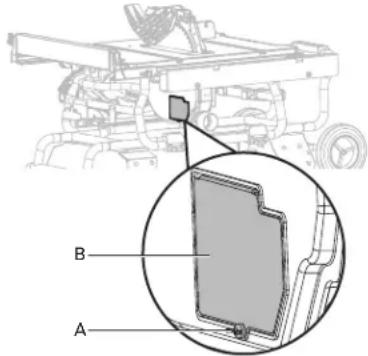
text_image
Technical diagram of a vehicle chassis with labeled parts A and B, showing structural components and an inset view.- Unplug the saw.
- Loosen and remove the thumbscrew (A), then open the small baffle (B).
- Clean out the excess dust, and push the small baffle in place, tighten the thumbscrew.
ADJUSTMENTS
⚠ WARNING: Before performing any adjustment, make sure tool is unplugged from power supply and switch is in off position. Failure to do so could result in serious personal injury.
⚠WARNING: Make sure the blade guard is reinstalled immediately after making any adjustment which requires it to be removed. Failure to heed this instruction could result in serious personal injury.
The table saw has been adjusted at the factory for making very accurate cuts. However, some components might have been jarred out of alignment during shipping. Also, over a period of time, readjustment will probably become necessary due to wear.
Carefully check alignment with a framing square before beginning adjustments to confirm whether they are necessary. Use test cuts after completing adjustments to avoid damaging workpiece.
RIVING KNIFE AND SAW BLADE ALIGNMENT (FIG. 29a-29b)
Blade and riving knife alignment is set at factory and in most cases will not need to be adjusted. However, the alignment should always be checked after installing blade or adjusting riving knife, and can be adjusted if necessary. If riving knife is out of alignment with blade, adjustment is needed. Riving knife must be in alignment front to back.
⚠️CAUTION: Unplug saw. With bevel adjustment assembly in vertical (0 degree) position, raise blade by turning height adjusting knob clockwise. Remove anti-kickback pawls and blade guard.
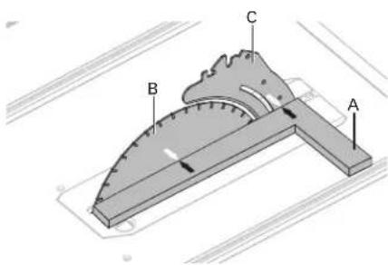
text_image
Diagram of a protractor with labeled parts A, B, and C for measurement or identificationFig. 29a
TO CHECK/ADJUST:
- Place framing square (A) (or straight edge) against both blade (B) and riving knife (C). Blade and riving knife are aligned if framing square contacts both blade and riving knife evenly with no gaps.
⚠CAUTION: Place framing square between carbide teeth and measure from blade. This step will ensure framing square is square against blade from front to back of blade.
- If blade and riving knife are not aligned, remove the table insert, loosen two set screws (D) (located left of riving knife) with 5 mm hex key, adjust the riving knife to left or right until it is aligned with the blade.
- Once properly aligned, securely tighten two set screws and reinstall the table insert.
⚠CAUTION: If the riving knife is out of alignment with the saw blade, adjustment is needed. The blade and riving knife must always be correctly aligned so that the cut workpiece will pass on either side of the riving knife without binding or twisting to the side.
WARNING: Improper riving knife alignment can cause kickback and serious injury.
⚠ WARNING: Make sure the blade guard and anti-kickback pawls are reinstalled immediately after making any adjustment which requires it to be removed. Failure to heed this instruction could result in serious personal injury.
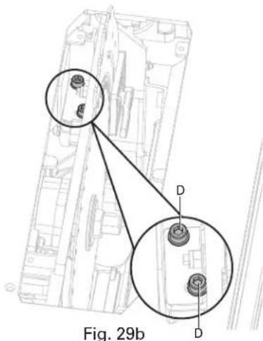
text_image
Fig. 29bALIGNING RIP FENCE TO BLADE (FIG. 30a-30b)
Rip fence and blade alignment is set at factory and in most cases will not need to be adjusted. However, the alignment should always be checked after installing blade or before making cuts, and can be adjusted if necessary. If rip fence is out of alignment with blade, adjustment is needed.
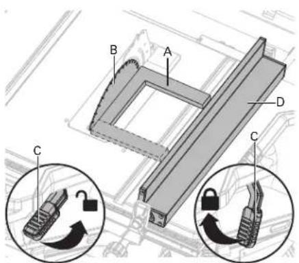
text_image
Technical diagram showing mechanical components labeled A, B, C, D with circular insets illustrating lock and gear mechanism.Fig. 30a
⚠WARNING: Rip fence must be aligned to blade so that wood does not bind, resulting in kickback. Failure to do so could result in serious personal injury.
DO NOT loosen any position screws for this adjustment until alignment has been checked with a square to be sure adjustment are necessary. Once screws are loosened, items must be reset.
⚠CAUTION: Unplug saw. Remove blade guard and anti-kickback pawls. Raise the blade by turning height adjusting knob.
TO CHECK/ADJUST:
- Place the framing square (A) beside the blade (B), and unlock the fence rails locking lever (C) to move the rip fence (D) up to the square.
- Lock the fence rails locking lever (C) and note the measurement on the rip scale.
- Move the fence back and rotate the framing square (A) 180^ to check the other side.
- If the two measurements are not the same, loosen the position screws (E) on the extension poles and then align it.
- Retighten the position screws with 4 mm hex key (supplied). Recheck alignment after position screws are retightened.
- Reinstall the blade guard and anti-kickback pawls.
- Make two or three test cuts using scrap wood. If the cuts are not true, repeat the process.

text_image
Technical diagram showing a mechanical or electrical component with labeled points and a central circular feature marked 'E'Fig. 30b
⚠CAUTION: The adjustment must be correct. If it is not, kickback could result in a serious injury and inability to make accurate cuts.
⚠ WARNING: Make sure the blade guard is reinstalled immediately after making any adjustment which requires it to be removed. Failure to heed this instruction could result in serious personal injury.
BEVEL ADJUSTMENT (FIG. 31a-31b)
This saw has positive stops that will quickly position the saw blade at 90^ ( 0^ ) or 45^ to the table. Angle settings of saw have been set at the factory and, unless damaged in shipping, should not require setting during assembly. After extensive use, they may need to be checked.

text_image
B A C EFig. 31a
TO CHECK 90° (0°) BEVEL:
- Turn power off and unplug the saw.
- Raise the blade to the maximum height by turning the height adjusting knob clockwise.
- Remove the anti-kickback pawls and blade guard.
- Using a framing square (A), set the blade (B) to exactly 90^ .
- If the blade stops bevelling before it gets to 90^ , loosen the 90^ stop set screw (C) (located at the left of the table insert), and then adjust it to 90^ .
- With the blade set at 90^ , slowly turn the 90^ stop set screw (C) until you feel resistance. Bevel the blade away from 90^ a little, and then back to the stop.
- Re-measure the angle and repeat the stop adjustment as necessary until the blade stops at 90^ .
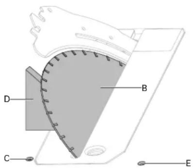
text_image
D B C EFig. 31b
TO CHECK 45° BEVEL:
- Turn power off and unplug the saw.
- Raise the blade to the maximum height by turning the height adjusting knob clockwise.
- Remove the anti-kickback pawls and blade guard.
- Using a triangle square (D), set the blade (B) to exactly 45^ .
- If the blade stops bevelling before it gets to 45^ , loosen the 45^ stop set screw (E) (located at the right of the table insert), and then adjust it to 45^ .
- With the blade set at 45^ , slowly turn the 45^ stop set screw (E) until you feel resistance. Bevel the blade away from 45^ a little, and then back to the stop.
- Re-measure the angle and repeat the stop adjustment as necessary until the blade stops at 45^ .
⚠️CAUTION: For easy of use, bevel adjust should stop at 45° and 90°.
⚠WARNING: Make sure the blade guard and anti-kickback pawls are reinstalled immediately after making any adjustment which requires it to be removed. Failure to heed this instruction could result in serious personal injury.
ADJUSTING RIP FENCE SCALE INDICATOR (FIG. 32)

text_image
Fig. 32- Unlock the fence rails lock lever (A).
- Set the blade at 0^ bevel and move the fence (B) in until it touches the blade.
- Lock the fence rails lock lever (A).
- Loosen the rip fence scale indicator screws (C, D) and set the red line (E) on the rip fence scale indicator (F) to read zero.
- Retighten the rip fence indicator screws (C, D). The top rip scale reads correctly only when the fence is mounted on the right side of the blade and is in position 1 (G) (for 0 to 27 in. ripping) [not the 35 in. position]. The bottom scale reads correctly only when the fence is mounted on the right side of the blade and in position 2 (H) (for 8 in. to 35 in. ripping).
ADJUSTING BEVEL INDICATOR (FIG. 33)
Adjust the red line on the bevel indicator if it is not aligned with zero when the blade is perpendicular to the table.
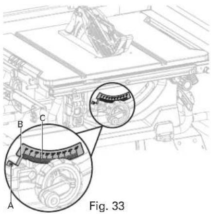
text_image
Fig. 33- With blade perpendicular to table, loosen screw (A).
- Set the bevel indicator (B) to align with 0^ on bevel scale (C).
- Retighten screw (A).
MAINTENANCE
⚠ WARNING: When servicing, use only identical replacement parts. Use of any other part may create a hazard or cause product damage.
⚠ WARNING: Always wear safety goggles or safety glasses with side shields during power tool operation or when blowing dust. If operation is dusty, also wear a dust mask.
⚠ WARNING: Before performing any maintenance, make sure the tool is unplugged from the power supply and switch is in the off position.
⚠ WARNING: DO NOT at any time let brake fluids, gasoline, petroleum-based products, penetrating oils, etc., come in contact with plastics parts. Chemicals can damage, weaken, or destroy plastic.
⚠ WARNING: Make sure the blade guard is reinstalled immediately after finishing any maintenance which requires it to be removed. Failure to heed this instruction could result in serious personal injury.
GENERAL MAINTENANCE
- Avoid using solvents when cleaning plastic parts. Most plastics are susceptible to damage from various types of commercial solvents and may be damaged by their use. Use clean cloths to remove dirt, dust, oil, grease, etc.
- Periodically check all clamps, nuts, bolts, and screws for tightness and condition. Make sure the table insert is in good condition and level with the working table.
- Check the blade guard assembly after performing maintenance to make sure it is installed correctly and functioning properly.
- Clean plastic part only with a soft damp cloth. DO NOT use any aerosol or petroleum solvents.
LUBRICATION
All of the bearings in this tool are lubricated with a sufficient amount of high grade lubricant for the life of the unit under normal operating conditions. Therefore, no further lubrication is required.
SERVICE AND REPAIRS
All quality power tools will eventually require servicing or replacement of parts because of wear from normal use. To assure that only authorized replacement parts will be used and that the double insulation system will be protected, all service (other than routine maintenance) must be performed by an AUTHORIZED HITACHI POWER TOOL REPAIR CENTER ONLY.
NOTE: Specifications are subject to change without any obligation on the part of HITACHI.
TROUBLESHOOTING

WARNING: To avoid injury from an accidental start, turn the switch OFF and always remove the plug from the power source before making any adjustments.
Consult Hitachi Authorized Service Center if for any reason the motor will not run.
| CORRECTIVE ACTIONPROBLEM CAUSEPROBLEM | ||
| Saw will not start. | Overload tripped.Saw is not plugged in.Fuse blown or circuit breaker tripped.Cord is damaged. | Allow motor to cool and reset by pushing overload reset switch.Plug in saw.Replace fuse or reset circuit breaker.Have the cord replaced by a qualified electrician. |
| Does not make 45° and 90° rip cuts. | Positive stop not adjusted correctly.Bevel angle pointer not set accurately.Rip fence not properly aligned. | See section “Bevel adjustment”.See section “Adjusting bevel indicator”.See section “Aligning rip fence to blade”. |
| Material pinches blade when ripping. | Rip fence not aligned with blade.Warped wood, edge against fence is not straight. | See section “Aligning rip fence to blade”.Select another piece of wood. |
| Material binds on riving knife. | Riving knife not aligned correctly with blade. | See section “Riving knife and saw blade alignment”. |
| Saw makes unsatisfactory cuts. | Dull blade.Blade mounted backwards.Gum or pitch on blade.Incorrect blade for work being done.Gum or pitch on blade causing erratic feed. | Replace blade.Turn the blade around.Remove the blade and clean with turpentine and coarse steel wool.Change the blade.Clean table with turpentine and steel wool. |
| Material kicked back from blade. | Riving knife not aligned correctly with blade.Feeding stock without rip fence.Riving knife not in place.Dull blade.The operator letting go of material before it is past saw blade.Miter angle lock knob is not tightened. | See section “Riving knife and saw blade alignment”.Install and use rip fence.Install and use riving knife (with guard).Replace blade.Push material all the way past saw blade before releasing work.Tighten lock knob. |
| Blade does not raise or bevel freely. | Sawdust and dirt in elevation/ beveling mechanisms. | Brush or blow out loose dust and dirt. |
| Blade does not come up to speed or reset trips too easily. | Extension cord too light or too long.Low house voltage. | Replace with adequate size cord.Contact your electric company. |
| Machine vibrates excessively. | The saw is not mounted securely to the stand.Stand is on uneven floor.Workbench is moving.Damaged saw blade. | Tighten all mounting hardware.Reposition on flat, level surface.Securely the workbench to floor.Replace blade. |
RENSEIGNEMENTS DE SÉCURITÉ IMPORTANTS
natural_image
Pure mechanical cross symbol without any text or labelsnatural_image
Simple line drawing of a plug and two socket outlets (no text or symbols)Fig. 1
text_image
Technical diagram showing exploded view of various mechanical parts with labeled sections A through Mnatural_image
Technical line drawing of a robotic device with a close-up inset showing internal components (no text or symbols)Fig. 4
text_image
Technical diagram of a mechanical assembly with labeled components A, B, C, and D, showing internal components and alignment views.Fig. 5a

text_image
EFig. 5b
INSTALLATION ET POSITION DU COUTEAU DIVISEUR (Fig.6a-6c)
⚠ PRÉCAUTION
text_image
Technical diagram of a mechanical assembly with labeled components D and Ctext_image
Technical diagram of a mechanical component with labeled parts C and Dtext_image
Technical diagram showing labeled components (A, B, C, D, E, F, G) of a mechanical assembly with dashed lines indicating connections.Fig. 7b
text_image
G F A A C H D EFig. 8b
natural_image
Pure mechanical assembly diagram without any text, numbers, or symbols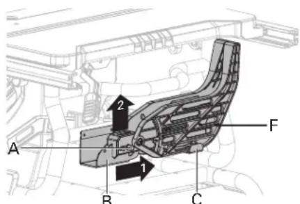
text_image
A B C F 1 2Fig. 9a
text_image
Technical diagram of a mechanical assembly with labeled parts A, F, G and cross-section view A-AFig. 9b
text_image
Diagram showing vehicle engine components with labeled parts A, B, C and numbered arrows indicating motion or movement.Fig. 11a
text_image
G E F D F E G DFig. 11b
text_image
Technical diagram of a vehicle engine compartment with labeled parts A, B, and CFig. 13a
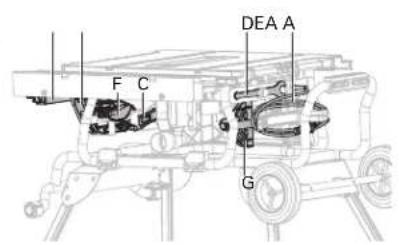
text_image
DEA A F C GFig. 13b Fig. 13c
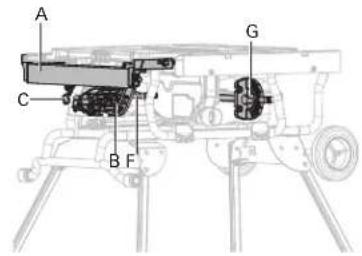
text_image
A C B F GREPLIER LE SOCLE (Fig. 14a-14f)
natural_image
Technical line drawing of a mechanical assembly with labeled component A (no text or symbols beyond label)Fig. 15
natural_image
Pure mechanical assembly diagram without any text, numbers, or symbolsÉLÉMENTS DE FONCTIONNEMENT
natural_image
Technical line drawing of a mechanical assembly with a magnified inset showing a detail (no text or symbols)Fig. 17
text_image
Technical diagram showing mechanical components with labeled parts A and a lock mechanism, likely illustrating a gear or valve assembly.Fig. 20a
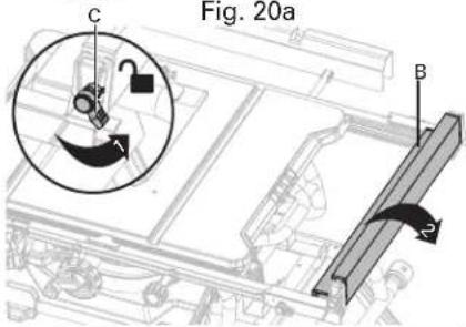
text_image
Fig. 20a C B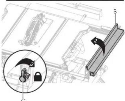
text_image
Technical diagram showing mechanical assembly with labeled components and a magnified inset highlighting a lock mechanism.Fig. 20b
LEVIER DE VERROUILLAGE DES RAILS DU GUIDE (Fig. 20a)
natural_image
Technical line drawing of a machine tool with conveyor belt and mechanical components (no text or symbols)Fig. 24b
COMMENT FABRIQUER UN BLOC POUSSOIR (FIG. 25a-25b)
natural_image
Technical line drawing of a mechanical assembly with no visible text or symbolsFig. 25b
Fig. 25a
text_image
Technical diagram of a mechanical assembly with labeled components A, B, and CFig. 26
natural_image
Pure mechanical assembly diagram without any text, numbers, or symbolsCONSEILS DE COUPE
text_image
Technical diagram of a vehicle chassis with labeled parts A and B, showing structural components and an inset view.text_image
Diagram of a protractor with labeled parts A, B, and C for measurement or design reference.Fig. 29a
VÉRIFIER/RÉGLER :
natural_image
Technical line drawing of a mechanical component with two circular insets showing internal features (no text or symbols)Fig. 29b
text_image
Technical diagram showing labeled components A, B, C, D with circular insets illustrating mechanical or electrical components.Fig. 30a
natural_image
Pure mechanical assembly diagram without any text, numbers, or symbolsnatural_image
Line drawing of a cable and two electrical socket (no text or symbols)Fig. 1
text_image
Technical diagram showing exploded view of various mechanical parts with labeled sections A through Mtext_image
H I G J Fig. 2cFig. 2b
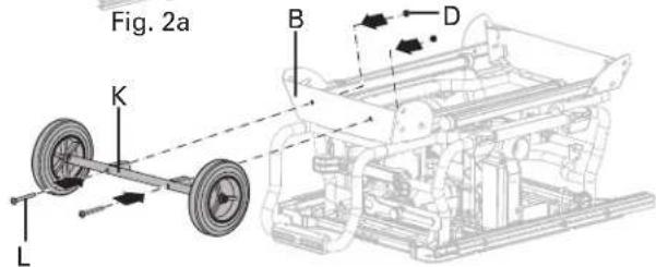
text_image
Fig. 2a B D K LFig. 2d

text_image
B M F Fig. 2eAPERTURA DEL SOPORTE (Fig. 3a-3d)
natural_image
Technical line drawing of a robotic device with a close-up inset showing internal components (no text or symbols)Fig. 4
text_image
Technical diagram of a mechanical assembly with labeled components A, B, C, and DFig. 5a
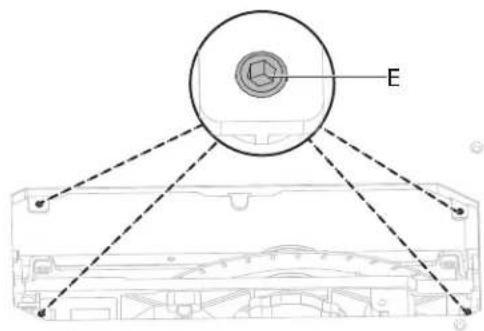
text_image
EFig. 5b
text_image
Technical diagram of a mechanical component with labeled parts D and Ctext_image
Technical diagram of a mechanical component with labeled parts C and Dtext_image
Technical diagram showing labeled components (A, B, C, D, E, F, G) of a mechanical or optical system with dashed lines indicating connections.Fig. 7b
text_image
Technical diagram of a mechanical assembly with labeled components A, B, and CFig. 8a
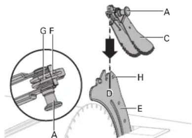
text_image
G F A A C H D EFig. 8b
natural_image
Pure mechanical assembly diagram without any text, numbers, or symbols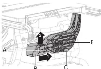
text_image
A B C F 1 2Fig. 9a
text_image
F A E D A F A G HFig. 9b

text_image
Fig. 3b I FFig. 9c
text_image
Technical diagram of a mechanical assembly with numbered components and magnified views highlighting parts 1, 2, 3, and 4.DA
Fig. 10b
text_image
Technical diagram showing mechanical assembly with labeled components A, B, C and numbered parts 1 to 4, including rotation arrows.Fig. 11a
text_image
G E F D F E G DFig. 11b
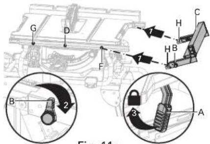
text_image
G D F B 2 3 A H C 1 7 H B Fig. 11aFig. 11c
text_image
Technical diagram of a mechanical assembly with labeled components A, B, and DPARA ALMACENAR LOS ACCESORIOS DE LA SIERRA DE MESA (Fig. 13a-13c)
text_image
Technical diagram of a vehicle engine compartment with labeled parts A, B, and CFig. 13a
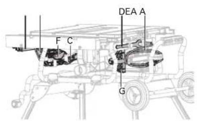
text_image
DEA A F C GFig. 13b Fig. 13c

text_image
A C B F GPLEGADO DEL SOPORTE (Fig. 14a-14f)
text_image
A B C D E F G H I J K L M N O P Q R S T U V W X Y Z Fig. 14b Fig. 14cFig. 14a
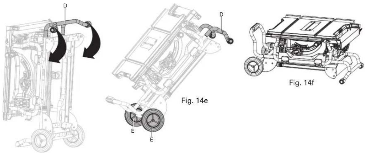
text_image
D D E E Fig. 14e Fig. 14fFig. 14d
natural_image
Technical line drawing of a mechanical assembly with labeled component A (no text or symbols beyond label)Fig. 15
natural_image
Pure mechanical assembly diagram without any text, numbers, or symbolsnatural_image
Technical line drawing of a mechanical assembly with a magnified inset showing a component labeled 'A' (no text or symbols present)Fig. 17
text_image
Diagram showing mechanical components with labeled parts A and lock mechanism, including a close-up of a gear mechanism.Fig. 20a

text_image
Fig. 20a C B
text_image
Technical diagram showing mechanical assembly with labeled components and a magnified inset highlighting parts C and 2.Fig. 20b
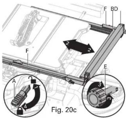
text_image
F BD 2 2 F E Fig. 20cPALANCA DE BLOQUEO DE LAS BARRAS DE TOPE (Fig. 20a)
text_image
2 1/2 in (63 mm) 3/4 in (19 mm) 1/4 in (6 mm) 1/8 in (3 mm) 12 in (305 mm) Fig. 24a 70°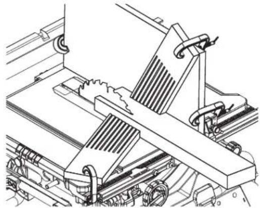
natural_image
Technical line drawing of a machine tool with conveyor belt and mechanical components (no text or symbols)Fig. 24b
CÓMO FABRICAR UN BLOQUE DE EMPUJE (FIG. 25a-25b)
natural_image
Technical line drawing of a mechanical assembly with no visible text or symbolsFig. 25b
Fig. 25a
text_image
Technical diagram of a mechanical assembly with labeled components A, B, and CFig. 26
natural_image
Pure mechanical assembly diagram without any text, numbers, or symbolsCONSEJOS DE CORTE
natural_image
Simple line drawing of two rectangular blocks with no text or symbolsnatural_image
Simple line drawing of two rectangular blocks with no text or symbolstext_image
Technical diagram of a vehicle's front-mounted launcher with labeled components A and B, showing internal structure and component layout.text_image
Diagram of a protractor with labeled parts A, B, and C, showing measurement markings.Fig. 29a
PARA CHEQUEAR/AJUSTAR:
text_image
Technical diagram showing mechanical assembly with labeled components A, B, C, D and circular insets illustrating lock mechanisms.Fig. 30a
text_image
Technical diagram of a mechanical assembly with numbered components for identification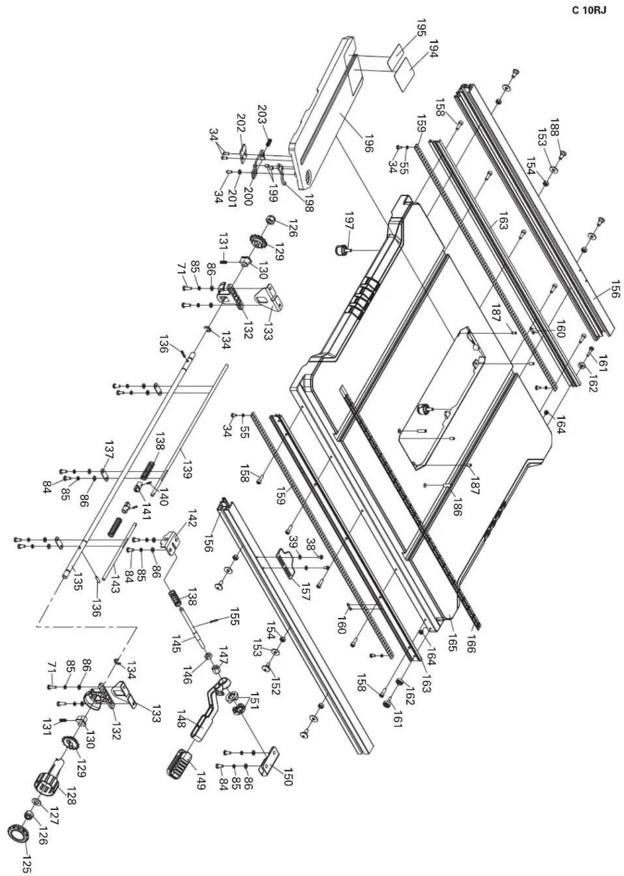
text_image
Technical schematic diagram of a mechanical assembly with numbered components and labeled partsC 10RJ
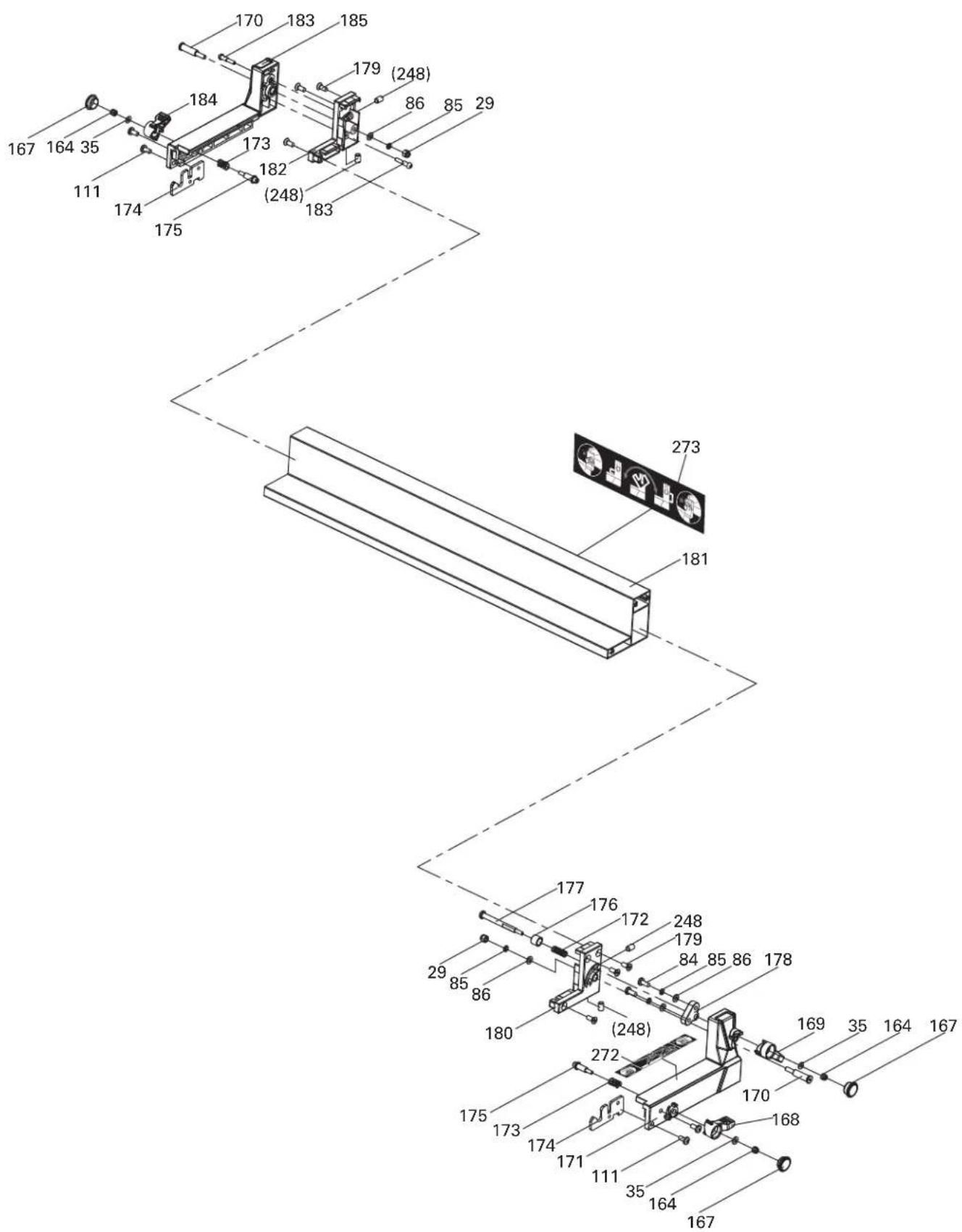
text_image
Technical diagram of a mechanical assembly with numbered components and labeled parts
text_image
Exploded view diagram of a hitachi device with numbered parts and labeled componentsC 10RJ
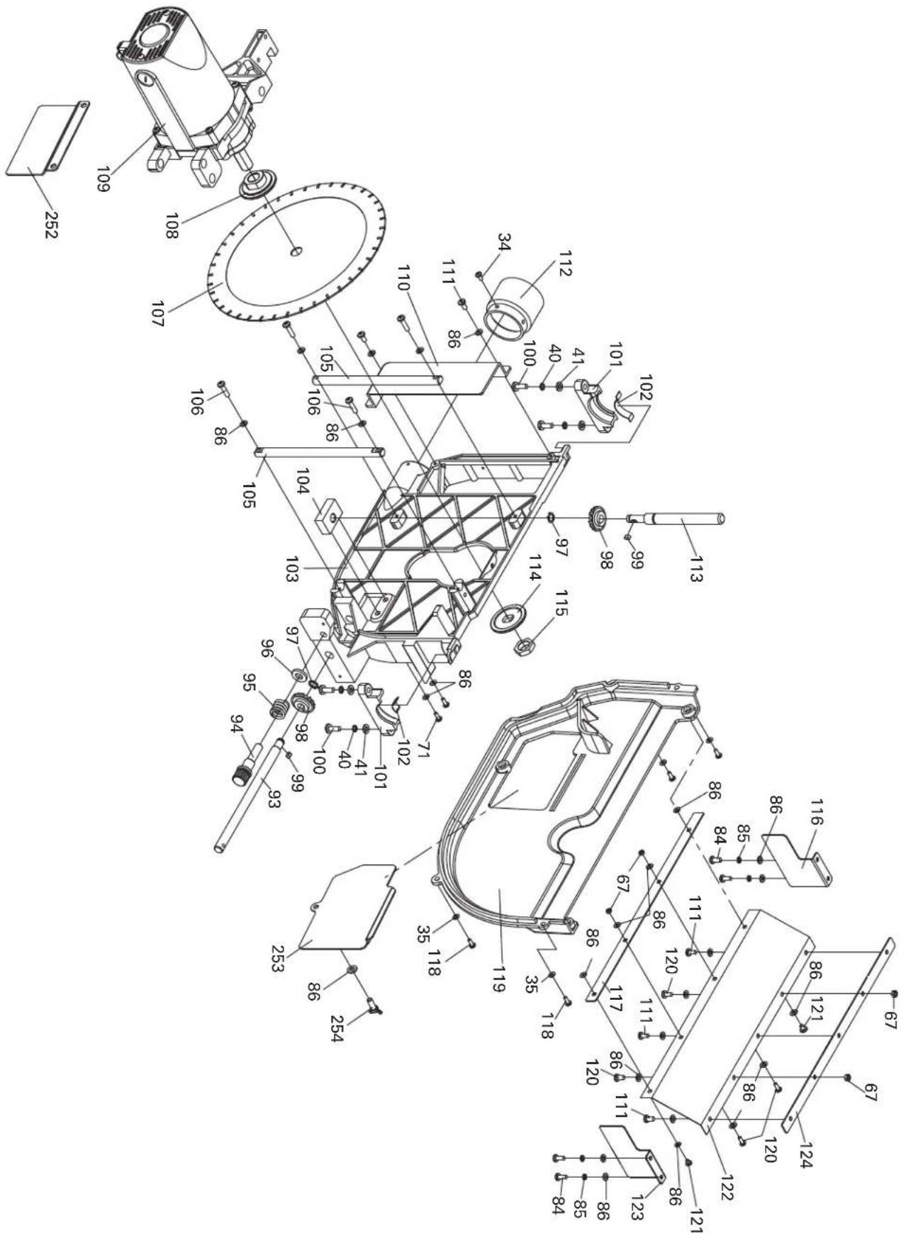
text_image
Technical schematic diagram of a mechanical assembly with numbered components and dimension annotations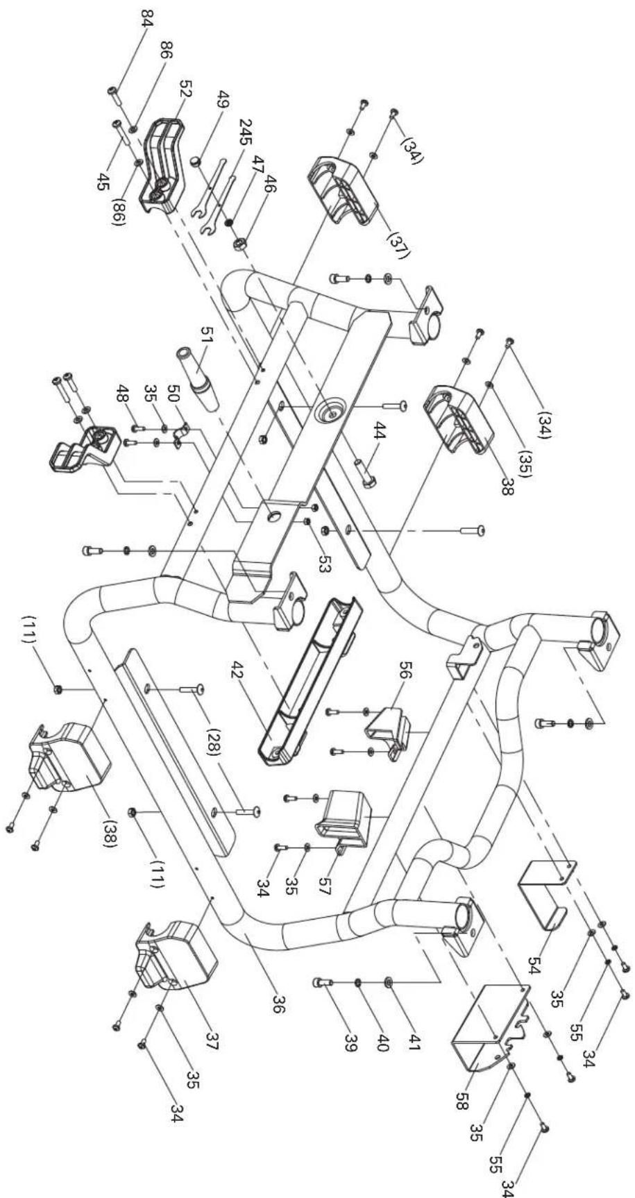
text_image
Technical diagram of a mechanical assembly with numbered components and dimension annotations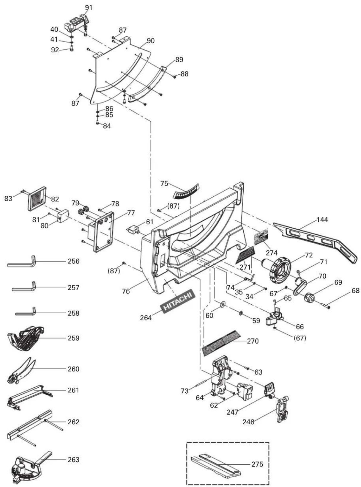
text_image
Exploded view diagram of a Hitachi device with numbered parts and exploded view, including labeled components like 80, 76, and 275.PARTS LIST
10" JOBSITE TABLE SAW MODEL NO.: C 10RJ
No. Description Qty
| 1 | Stand foot | 4 |
| 2 | Stand leg (A) | 3 |
| 3 | Split washer | 4 |
| 4 | Flat washer 8 | 4 |
| 5 | Spring | 4 |
| 6 | Friction pad 13 | 4 |
| 7 | Stop pin | 4 |
| 8 | Friction pad 8 | 8 |
| 9 | Bolt | 4 |
| 10 | Support plate assembly (A) | 1 |
| 11 | Lock nut M8 | 18 |
| 12 | Wheel shaft assembly | 1 |
| 13 | Hexagon lobular socket pan head screw M8 x 90 | 2 |
| 14 | Wheel | 2 |
| 15 | Flat washer 10 | 2 |
| 16 | Lock nut M10 | 2 |
| 17 | Adjustable foot (B) | 1 |
| 18 | Adjustable foot (A) | 1 |
| 19 | Adjustable leg | 1 |
| 20 | Support plate assembly (B) | 1 |
| 21 | Horizontal support tube assembly M6 x 40 | 1 |
| 22 | Lock nut M6 | 3 |
| 23 | Footing | 2 |
| 24 | Hexagon socket cap screws M6 x 40 | 2 |
| 25 | End cap | 2 |
| 26 | Handle assembly | 1 |
| 27 | Hexagon lobular socket pan head screw M8 x 12 | 4 |
| 28 | Hexagon lobular socket pan head screw M8 x 45 | 8 |
| 29 | Lock nut M5 | 4 |
| 30 | Support pad (B) | 1 |
| 31 | Support tube assembly | 1 |
| 32 | Support pad (A) | 1 |
| 33 | Cross pan head screw M5 x 45 | 2 |
| 34 | Cross pan head screw M4 x 8 | 25 |
| 35 | Flat washer 4 | 26 |
| 36 | Frame assembly | 1 |
| 37 | Footing (A) | 2 |
| 38 | Footing (B) | 2 |
| 39 | Hexagon socket cap screws M6 x 16 | 4 |
| 40 | Spring washer 6 | 10 |
| 41 | Flat washer 6 | 10 |
| 42 | Miter gauge storage | 1 |
| 44 | Hexagon bolt M8 x 30 | 1 |
| 45 | Cross pan head screw M5 x 40 | 2 |
No. Description Qty
| 46 | Hex nut M8 | 1 |
| 47 | Holder for blade | 1 |
| 48 | Cross pan head screw M4 X 12 | 2 |
| 49 | Locking knob | 1 |
| 50 | Wire clip | 1 |
| 51 | Antiflex bushing | 1 |
| 52 | Cord warp | 2 |
| 53 | Hex nut M4 | 2 |
| 54 | Blade guard storage (B) | 1 |
| 55 | Spring washer 4 | 8 |
| 56 | Push sticker storage (A) | 1 |
| 57 | Push sticker storage (B) | 1 |
| 58 | Blade guard storage (A) | 1 |
| 59 | Nut for overload protection | 1 |
| 60 | Label for overload protection | 1 |
| 61 | Overload protection | 1 |
| 62 | Swicth | 1 |
| 63 | Cross recessed pan head tapping screw ST4.2 x 16 | 4 |
| 64 | Switch panel | 1 |
| 65 | Hexagon socket head cap screws M5 x 12 | 1 |
| 66 | Locking handle | 1 |
| 67 | Hex nut M5 | 4 |
| 68 | Bolt | 1 |
| 69 | Knob | 1 |
| 70 | Rotation lever | 1 |
| 71 | Cross pan head screw M5 x 16 | 7 |
| 72 | Rotation wheel | 1 |
| 73 | Rotation pin | 1 |
| 74 | 45° Pointer | 1 |
| 75 | Bevel label | 1 |
| 76 | Front panel | 1 |
| 77 | Switch cover | 1 |
| 78 | Cross recessed pan head tapping screw ST3.9 x 9.5 | 4 |
| 79 | Strain relife bushing | 2 |
| 80 | Soft start | 1 |
| 81 | Cross recessed pan head tapping screw ST2.9 x 6.5 | 2 |
| 82 | Cover for soft start | 1 |
| 83 | Cross recessed pan head tapping screw ST2.9 x 9.5 | 2 |
| 84 | Cross pan head screw M5 x 12 | 20 |
| 85 | Spring washer 5 | 24 |
| 86 | Flat washer 5 | 50 |
| 87 | Cross recessed pan head tapping screw ST4.2 x 9.5 | 7 |
| 88 | Cross pan head screw M4 x 10 | 3 |
| 89 | Angle adjusting base | 1 |
No. Description Qty
| 90 | Back plate | 1 |
| 91 | Holder (B) | 1 |
| 92 | Hexagon bolt M6 x 16 | 2 |
| 93 | Up and down adjusting rod (A) | 1 |
| 94 | Compression screw rod | 1 |
| 95 | Compression spring | 1 |
| 96 | Washer | 1 |
| 97 | Washer on shaft | 2 |
| 98 | Bevel gear | 2 |
| 99 | A type Key | 2 |
| 100 | Cross pan head screw M6 x16 | 4 |
| 101 | Holder (A) | 2 |
| 102 | Spacer shim | 2 |
| 103 | Trunion | 1 |
| 104 | Adjusting seat | 1 |
| 105 | Guide pillar | 2 |
| 106 | Cross pan head screw M5 x 20 | 4 |
| 107 | Blade | 1 |
| 108 | Blade inner flange | 1 |
| 109 | Motor | 1 |
| 110 | Cover plate | 1 |
| 111 | Cross pan head screw M5 x 10 | 9 |
| 112 | Dust port | 1 |
| 113 | Up and down adjusting rod (B) | 1 |
| 114 | Blade outer flange | 1 |
| 115 | Arbor nut | 1 |
| 116 | Lower protection guard (A) | 1 |
| 117 | Lower protection dead plate (A) | 1 |
| 118 | Cross pan head screw M4 x 10 | 4 |
| 119 | Trunion protection guard | 1 |
| 120 | Cross pan head screw M5 x 8 | 4 |
| 121 | Cross recessed pan head tapping screw ST4.8 x 9.5 | 2 |
| 122 | Lower protection | 1 |
| 123 | Lower protection guard (B) | 1 |
| 124 | Lower protection dead plate (B) | 1 |
| 125 | Knob cover | 1 |
| 126 | Hex nut M10 | 2 |
| 127 | Flat washer 10 | 1 |
| 128 | Rotation knob | 1 |
| 129 | Adjusting gear | 2 |
| 130 | Adjusting support seat (C) | 2 |
| 131 | Adjusting spring | 2 |
| 132 | Adjusting support seat (B) | 2 |
| 133 | Adjusting support seat (A) | 2 |
| 134 | Split washer | 2 |
| 135 | Adjusting rod | 1 |
| 136 | Spring pin | 2 |
| 137 | Clamp | 2 |
| 138 | Compression spring | 3 |
No. Description Qty
| 139 | Rear locking rod (B) | 1 |
| 140 | Spring pin | 2 |
| 141 | Slider (A) | 2 |
| 142 | Location-limited plate (B) | 1 |
| 143 | Rear locking rod (A) | 1 |
| 144 | Push sticker | 1 |
| 145 | Front locking rod | 1 |
| 146 | Hex nut M8 | 1 |
| 147 | Longer nut M8 (B) | 1 |
| 148 | Locking lever | 1 |
| 149 | Sheath for locking lever | 1 |
| 150 | Location-limited plate (A) | 1 |
| 151 | Locking block | 2 |
| 152 | Positioning screw (B) | 3 |
| 153 | Big flat washer 6 | 6 |
| 154 | Hex nut M6 | 6 |
| 155 | Spring pin | 1 |
| 156 | Sliding rail | 2 |
| 157 | Pointer | 1 |
| 158 | Hexagon socket head cap screws M5 x 16 | 10 |
| 159 | Rack | 2 |
| 160 | Friction pad | 2 |
| 161 | Adjusting bolt | 2 |
| 162 | Adjusting wheel | 2 |
| 163 | Rail | 2 |
| 164 | Lock nut M4 | 4 |
| 165 | Worktable | 1 |
| 166 | Scale label | 1 |
| 167 | Cover | 2 |
| 168 | Lever (left) | 1 |
| 169 | Locking piece | 1 |
| 170 | Rotation bolt | 2 |
| 171 | Rip fence holder base (left) | 1 |
| 172 | Spring | 1 |
| 173 | Locking spring | 2 |
| 174 | Fixing plate | 2 |
| 175 | Locating pin | 2 |
| 176 | Pin shaft | 1 |
| 177 | Clamping bush | 1 |
| 178 | Fixing plate | 1 |
| 179 | Cross recessed countersunk head screw M5 x 12 | 6 |
| 180 | End cap (left) | 1 |
| 181 | Rip fence | 1 |
| 182 | End cap (right) | 1 |
| 183 | Cross recess head screw M5 x 20 | 2 |
| 184 | Lever (right) | 1 |
| 185 | Rip fence holder base (right) | 1 |
| 186 | Hexagon socket bolt M6 x 20 | 2 |
| 187 | Hexagon socket bolt M5 x 10 | 4 |
No. Description Qty
| 188 | Position screw (A) | 3 |
| 189 | Extension table | 1 |
| 190 | M14 hexagon socket screw | 2 |
| 191 | Stop collar | 2 |
| 192 | Cross pan head screw M4 x 6 | 4 |
| 193 | Extesion rod | 2 |
| 194 | Base plate A | 1 |
| 195 | Base plate B | 1 |
| 196 | Table insert | 1 |
| 197 | Knob | 2 |
| 198 | Latch plate (B) | 1 |
| 199 | Cylindrical pin | 2 |
| 200 | Latch plate (A) | 1 |
| 201 | Big flat washer 4 | 1 |
| 202 | Rear pressing plate | 1 |
| 203 | Spring | 1 |
| 204 | Right blade guard | 1 |
| 205 | Bolt | 4 |
| 206 | Latch cap | 2 |
| 207 | Split washer | 2 |
| 208 | Flat washer | 2 |
| 209 | Spring | 2 |
| 210 | Special bolt | 1 |
| 211 | Eccentric hand | 1 |
| 212 | Knob | 1 |
| 213 | Latch | 1 |
| 214 | Cylindrical pin | 2 |
| 215 | Cam pressing plate | 1 |
| 216 | Compressing spring (A) | 1 |
| 217 | Anti-kick back pawl (A) | 1 |
| 218 | Spring pin | 1 |
| 219 | Hexagon socket set screw with flat point M4 x 6 | 1 |
| 220 | Supporting seat | 1 |
| 221 | Anti-kick back pawl spring | 1 |
| 222 | Washer on shaft | 2 |
| 223 | Anti-kick back pawl (A) | 1 |
| 224 | Fixing holder | 1 |
| 225 | Steel ball | 1 |
| 226 | Spring | 1 |
| 227 | Hexagon socket set screw with flat point | 1 |
| 228 | Riving knife | 1 |
| 229 | Stop pin | 1 |
| 230 | Sliding detent | 1 |
| 231 | Snap spring | 2 |
No. Description Qty
| 232 | Blade guard supporting seat | 1 |
| 233 | Left blade guard | 1 |
| 234 | Handle for miter gauge | 1 |
| 235 | Miter gauge | 1 |
| 236 | Pointer | 1 |
| 237 | Steel ball | 1 |
| 238 | Pointer spring | 1 |
| 239 | Hexagon socket set screw with flat point M6 x 12 | 1 |
| 240 | Bar for miter gauge | 1 |
| 241 | Bolt (A) | 1 |
| 242 | Cross recessed pan head tapping screw | 2 |
| 243 | Adjusting shim | 1 |
| 244 | Big flat washer | 1 |
| 245 | Blade wrench | 2 |
| 246 | Swicth flap | 1 |
| 247 | Switch lock | 1 |
| 248 | Hexagon socket set screw with flat point M5 x 8 | 4 |
| 249 | Clamping bush | 1 |
| 250 | Spring | 1 |
| 251 | Leg stop collar | 4 |
| 252 | Blade protection plate | 1 |
| 253 | Small baffle | 1 |
| 254 | Thumbscrew M5 x 12 | 1 |
| 255 | Friction pad | 3 |
| 256 | 5mm Hex key | 1 |
| 257 | 4mm Hex key | 1 |
| 258 | 2.5mm Hex key | 1 |
| 259 | Blade guard assembly | 1 |
| 260 | Anti-kickback pawls assembly | 1 |
| 261 | Rip fence assembly | 1 |
| 262 | Outfeed support assembly | 1 |
| 263 | Miter gauge assembly | 1 |
| 264 | HITACHI label A | 1 |
| 265 | HITACHI label B | 1 |
| 266 | Warning label A | 1 |
| 267 | Warning label B | 1 |
| 268 | Warning label C | 1 |
| 269 | Warning label D | 1 |
| 270 | Warning label E | 1 |
| 271 | Warning label F | 1 |
| 272 | Rip fence label A | 1 |
| 273 | Rip fence label B | 1 |
| 274 | Name plate | 1 |
| 275 | Dado table insert (Optional accessory) | 1 |
LISTE DES PIÈCES
BANC DE SCIE JOBSITE DE 10 PO
Issued and distributed by

Hitachi Koki U.S.A., Ltd.
PO Box 970
Braselton, GA 30517

Hitachi Koki Canada Corp.
450 Export Blvd. Unit B,
Mississauga ON L5S 2A4
612
Code No. C99721261
Printed in China