
CRM1045 - Compressor Ferm - Free user manual and instructions
Find the device manual for free CRM1045 Ferm in PDF.
| Product type | Air compressor |
| Brand | Ferm |
| Model | CRM1045 |
| Tank capacity | 24 liters |
| Air flow rate | 155 L/min |
| Maximum pressure | 8 bar |
| Weight | 23 kg |
| Sound pressure level | 93 dB(A) |
| Power supply | 230 V / 50 Hz |
| Recommended fuse | 16 A |
| Motor power | 1100 W (1.5 HP) |
| Motor oil type | SAE 10W30 synthetic |
| Pressure regulation | Automatic via pressure switch |
| Quick coupling | Yes, for pneumatic tool |
| Pressure gauges | 2 (tank and regulated pressure) |
| Safety valve | Yes |
| Air filter | Yes, washable |
| Overload switch | Yes, resettable |
| Electrical connection | Shock-proof plug |
| Operating temperature | 0°C to +40°C |
| Usage | Domestic |
| Warranty | See included warranty card |
Frequently Asked Questions - CRM1045 Ferm
User questions about CRM1045 Ferm
0 question about this device. Answer the ones you know or ask your own.
Ask a new question about this device
Download the instructions for your Compressor in PDF format for free! Find your manual CRM1045 - Ferm and take your electronic device back in hand. On this page are published all the documents necessary for the use of your device. CRM1045 by Ferm.
USER MANUAL CRM1045 Ferm
The numbers in the following text correspond with the pictures at page 2 - 4.

Read the operating instructions carefully before using this device. Familiarise yourself with its functions and basic operation. Service the device as per the instructions to ensure that it always functions properly. The operating instructions and the accompanying documentation must be kept in the vicinity of the device.
Contents
- Machine details
- Safety instructions
3.Use - Maintenance
1. MACHINE DETAILS
Technical specifications
Voltage 230V
Frequency 50 Hz
Capacity 1.5 hp (1100 W)
ldling speed 2850/min
IP Class IP 20
Tank contents 24 litre
Air intake 155 l/min
Max. outlet pressure 8.0 Bar
Weight 23 kg
Sound power level 93 dB (A)
The value of the noise level may rise from 1 to 10 dB(A) as a function of the environment in which the compressor will be installed.
Product information
Fig. A
1 Cover
2. Handle
3. Switch
4. Automatic stop
5. Pressure regulator
- Quick coupler (regulated outlet pressure)
- Pressure gauge (pressure regulator)
- Pressure gauge (tank)
- Safety valve
- Pressurepipe
11.Airfilter
12.Oilcap - Oil level inspection glass
- Drain cock
15.Overloadswitch
2. SAFETY INSTRUCTIONS
Explanation of symbols

Denotes risk of personal injury, loss of life or damage to the tool in case of non-observation of the instructions in this manual.

Risk of electric shock.

Caution: the compressor could start automatically in case of a black-out and subsequent reset

Wear ear protection.

Sound power level
Special safety instructions
- Warning! The compressor may only be used in suitable rooms (with good ventilation and an ambient temperature from 0^ to +40^ ).
- Check that the tank is fully decompressed before connections with the tank are unscrewed.
It is prohibited to make holes in, or welds to, or purposely to distort the compressed air tank. - Do not perform any actions on the compressor without first having taken the plug out of the plug socket.
- Do not aim water jets or jets of flammable liquids at the compressor.
- Do not place flammable objects near the compressor.
- Switch the switch (3) to the "0" position (OFF) during dwell time. (fig. 11)
-
Never aim the air jet at persons or animals (fig. 20).
-
Do not transport the compressor with the tank pressurised.
N.B.: some parts of the compressor such as the head and the feed-through pipes may reach high temperatures. Do not touch these parts to avoid burns (fig. 12-13). - Transport the compressor by lifting it or by using the special grips or handles (fig. 5-6).
Children and animals should be kept far away from the area of operation of the machine.
If you use the compressor to spray paint:
a) Do not work in enclosed spaces or near naked flames.
b) Make sure that the environment in which you will be working has dedicated ventilation.
c) Protect your nose and mouth with a dedicated mask (fig. 21). - Do not use the compressor when the electrical cable or the plug is damaged, and instruct an authorised Support Service to replace them with an original part.
- When the compressor is placed on a surface higher than the floor, it should be secured to prevent it from falling down during operation.
- Do not put objects or your hands in the protective covers to avoid physical damage and damage to the compressor.
- Do not use the compressor as a blunt instrument against persons, objects or animals in order to prevent serious damage.
- If the compressor is no longer in use, always take the plug out of the plug socket.
Always make sure that compressed-air hoses are used for compressed air and which are characterised by a maximum pressure adjusted to that of the compressor. Do not try to repair the hose if it is damaged.
Electrical safety
Earthing regulations
This compressor has to be earthed while in use in order to protect the operator against electrical shocks. The compressor is provided with a two-core cable plus an earth. The electrical connection has to be made by a qualified technician. We recommend never disassembling the compressor and neither making any other connections into the pressure regulator. Repairs should be carried out by authorised Support Services or by other qualified centres.

Never forget that the earthing core is the green or the yellow/green wire. Never connect this green wire to a terminal under load.
Before replacing the plug of the feed, make sure that the earth cable is connected. If in doubt, please call in a qualified electrician and have the earthing checked.
Power supply
- The compressor is equipped with a mains cable with shock-proof plug. This can be connected to any 230V /50Hz shock proof socket which is protected by a 16A fuse.
- The motor is fitted with an overload switch (15). If the compressor overloads, the overload switch switches the equipment off automatically to protect the compressor from overheating. If the overload switch triggers, switch off the compressor using the ON/OFF switch (3) and wait until the compressor cools down. Then press the overload switch (15) and restart the compressor.
- Long supply cables, extensions, cable reels etc cause a drop in voltage and can impede motor start-up. Do not use cables longer than 10m . Ferm advises to use a longer air hose instead.
It can be more difficult to start-up the motor during conditions of temperatures below 0C.
3. USE

For household use only
NB: The information you will find in this manual has been written to assist the operator in the use and maintenance of the compressor. Some illustrations in this manual show details which may differ from those of your compressor.
Installation
After having taken the compressor out of its packaging (fig. 1) and having checked that it is in perfect condition, and having noted that no damage occurred during transport, the following acts should be performed. If not yet fitted, fit the rubber feet and the wheels on the tank according
to the instructions represented in fig. 2. Place the compressor on a flat surface or at a maximum slope of 10^ (fig.3), in a well ventilated area, protected against atmospheric factors and not in explosive surroundings. If the surface area is sloping and smooth, make sure that the compressor will not move when in operation. If the surface area is a board or a shelf of a bookcase, just make sure that they cannot fall down by securing them properly. For proper ventilation and effective cooling, it is important that the compressor is positioned at least 100cm from the wall (fig.4).

Make sure that the compressor is transported in the right way, do not turn it upside down and don't lift it with hooks or ropes (fig. 5-6).
Filling the compressor with oil.
Your compressor is supplied with oil which is already included in the carter. Before use, remove the transport cap on the carter (12), and replace it by the regular oil cap (fig 7). Before use, ensure that oil level is sufficient. This can be checked by checking the oil inspection glass (13). When compressor is placed horizontally, the oil level shall reach the red mark.
Installing the air filters.
Remove the transport lids and replace them with the supplied air filters before using the compressor.
Starting up
- Check whether the mains voltage corresponds to that indicated on the electrical specification plate (fig. 10), the permitted tolerance range should be within 5% .
- Press the switch (3) situated on the upper part into the "0" position according to the pressure regulator type fitted on the device (fig. 11).
- Put the plug in the plug socket (fig. 9) and start the compressor up by putting the switch(3) of the pressure regulator in the "l" position. The operation of the compressor is fully automatic. The pressure regulator will stop the compressor when the maximum value has been reached and start it up when the pressure drops below the minimum value. Normally the difference in pressure is approx. 2 Bar/29 psi between the maximum and the minimum value. For instance - The compressor will stop
when it reaches 8 Bar (116 psi) (this is the maximum operating pressure) and will start up automatically when the pressure within the tank has dropped to 6 Bar (87 psi).

The head/cylinder/transmission pipe assembly may reach high temperatures, so take care when working close to these parts and do not touch them to avoid burns (fig. 12 - 13).
Adjusting the operating pressure
Fig. 14
It is not necessary continuously to use the maximum operating pressure, the compressed-air tools often require less pressure. With regard to compressors supplied with a pressure reduction valve it is necessary to set the operating pressure properly.
It is possible to set the operating pressure by using the turning knob(5) on the reduction valve.
- By turning clockwise, the pressure will be increased.
- By turning anti-clockwise, the pressure will be reduced.
The compressor has two pressure gauges and one point to connect an air hose:
- Pressure gauge (7): The pressure of this outlet can be regulated with help of the reduction valve (5).
Pressure gauge (8): tank pressure
Hints for accurate adjustment of the pressure regulation:
- Turn the turning knob (5) anti-clockwise till pressure is fully released
- Connect the air tool you want to use to the quick coupler (6)
- Activate the air tool shortly, so the pressure gauge (7) will show the right pressure level
- Turn the turning knob (5) clockwise, till the pressure gauge (7) shows the pressure level you need
- Your air tool is now ready to use.
Note: when not connecting an air tool while adjusting the pressure, it might occur the pressure gauge (7) is not reacting accurately on the pressure drop.
4. MAINTENANCE

Make sure that the plug is removed from the mains when carrying out maintenance work on the motor.
The machine has been designed to operate over a long period of time with a minimum of maintenance. Continuous satisfactory operation depends upon proper machine care and regular cleaning. Before interfering in any way whatsoever with the compressor, please make sure that:
- The switch button is in the "0" position and the power plug is removed from the power socket
- The air tank is fully decompressed (both pressure gauges must be pointed at 0 Bar)
Malfunction
Should the machine fail to function correctly, a number of possible causes and the appropriate solutions are given below:
Air loss
- May be caused by a poor seal of a connection.
- Check all air connections by wetting them with a soapy water solution (Never use the solution nearby electric connections)
- When the tank is empty and being filled. The user might hear a sisseling sound by the pressure switch. This is normal and will stop before the compressor reach a pressure of 1.5 bar
- Check if the drain valve (14) is closed well
The compressor will not start
If the compressor is difficult to start, check:
- whether the voltage of the mains corresponds to that on the specification plate (fig. 10)
- whether electrical extension cables are being used with a faulty core or length.
- whether the operating environment is too cold (below 0^ ).
- whether there is electricity supply (plug properly connected, magneto-thermal fuses not broken).
- whether the carbon brushes are not worn out.
The compressor does not shut off
If the compressor does not shut off when the maximum pressure has been reached, the safety valve of the tank will be activated. It is necessary to contact the nearest authorised Support Service for the repair.

Repairs and servicing should only be carried out by a qualified technician or service firm.
Cleaning
Regularly clean the machine housing with a soft cloth, preferably after each use. Keep the ventilation slots free from dust and dirt.
If the dirt does not come off use a soft cloth moistened with soapy water. Never use solvents such as petrol, alcohol, ammonia water, etc.
These solvents may damage the plastic parts.
Drain the tank
Compressing air will cause water in the tank.
Regularly drain the water from the tank to prevent tank corrosion (fig 16):
- First reduce the pressure in the tank till approximately 2 bar by connecting and activating an air tool.
- Then slowly turn the drain valve (14) on the lower side of the tank open.
- The water in the tank will now leak out of the tank
Take care when compressed air is in the tank because the water can come out with some force. Recommended pressure max. 1-2 Bar.
Clean the air filter
It is recommended to disassemble the suction filter every 50 operating hours and to clean the filter element by blowing it with compressed air (fig. 15). It is recommended that the filter element is replaced at least once a year if the compressor is working in a clean environment; more often if the environment in which the compressor is situated is dusty.
Replacing/topping up oil
The compressor has been supplied with synthetic oil "SAE 10W30". It is recommend to fully replace the oil of the pump system within the first 100 operating hours.
- Unscrew the drain plug (gauge) (13) on the sump lid, let all the oil run out and screw back the plug (fig. 17).
- Fill the oil via the upper hole of the sump lid (fig.18) until the level indicated on the gauge (13) (fig. 8) has been reached.

the oil level of the pump systemevery week and if necessary top
The synthetic oil has the advantage that it does not lose its characteristics, either in summer or in winter periods.
For replacement of oil the table below should be adhered to.
type Operating hours
Multigrade oil SAE 10W30 100 or 6 months
Faults
Should a fault occur, e.g. after wear of a part, please contact the service address on the warranty card. In the back of this manual you find an exploded view showing the parts that can be ordered.
ENVIRONMENT
To prevent damage during transport, the appliance is delivered in a solid packaging which consists largely of reusable material.
Therefore please make use of options for recycling the packaging.

Faulty and/or discarded electrical or electronic apparatus have to be collected at the appropriate recycling locations.
WARRANTY
The warranty conditions can be found on the separately enclosed warranty card.
KOMPRESSOR 1.5PS - 1100W - 24L
Specifications techniques
Voltage 230V
Fréquence 50 Hz
Puisance 1.5 CV (1100 W)
Ralenti 2850/min
Classe IP IP 20
2. BEZPECNOSTNL POKNY
Vyznam symbolu

PnmuTka: kkuo nic yac peryIIOBAHH TcCKy He nD'EDHyBaTu INHeBMaTuHn IHCTpyMeHT, MaHOMeTp (7) MoKe HToUHO pearyBaTu Ha nepenad TcCKy
4. TEXHIUHE OBCIyROBYAHHH
Ley npictpi po3p06nHn TaK, 0o Bin MoKe npauoBAtn npotarom Tpnbaloro nepiody acy 6e3TexhiHOrO o6cIyroByBaHHr. TpNbAla 3aIOBilbHa pObota 3aIexNtB BiD npabunbHoro DORJyTa peryIapHOrO OuIeHNr. Ipeed BIKOHaHHm 6yDb-IAkX PoBt 3 KOMnPecopom, 6yDb lacKa, nepekoHaTecb, 0o:
Komnpecop He BmmkaTbcra
KUO KOMnpecop He BUMKaETbCRA, KOJI
DOcraTbCMAKcMaJbHe 3HaueHHa TnCKy,
CpauBoBye 3anobixHn Klanah 6aky.
Heo6xIINO 3BepHyTncy HaN6JIuXuN ophiHn
cepBicn UeHTP dJa BVKOHaHH peMOHTy.

Ipekehaumecb, uo eunka eumraheHa 3 po3emku kuehneHHn, npu bukoHnHi mexhiHOZO o6cny20eYbaHHa dbuyna.
OuHnHn
PeryIaRHO ouuuyte Kopnyc npncTroHO M'koHOr RaHcyko,6axaHo nicra Koxhoro BnKOpNCTaHHr. TpImaTe BeHTnlaui Hi OTBOpN uHCTmMu Ta He 3a6ntMn NINOM Ta 6pyoM. KaO 6pyd He BxOOnTb NOBHicTIO,CKOpNCtaTecb RaHcyipKO,3MOeHOU y MNlbHomy po3uHi. HikOI He BnKOpNCTOBYTe PO3uHHNKu,Taki JAK 6eH3uH, aIKoROLb, BOHNI PO3uH amiaKy,TOIo. Lj PO3uHHNK MoKyTb NOWKoDHTn PnaCTNKObi Detani.
Дренихбaka
CTNCHyTe NOBITpI NOCJyKuTb npUHNO HnABHocTi BOiB 6aKy. Uo6 3anobirTu Kopo3ii 6aKy, peryIarpHo IpehaxyIte 3 HbOrO B0dy (pnc. 16).
CnoaTky 3Hn3bTe TnCK y 6aKy npu6n3Ho Ha 2 6ap.Дяцboro nID'EDHaNte i yBIMKHiTb nHeBMATnuHm IHCTpyMent.
-Дani nobinbno nobepTaTe dpehaxHn KpaH (14), 3naTbC3 HxKBoi CTOpOH nOTBOPy 6aka.
Boda noUHe BUNIBaTncs 3 6aKy. BybTe o6epeKHi, KOJI CTnCHe He NobITpy 3HaxOuNTbcra y nlau, TOMy IIO BOda MoKe BnPBaTncs C neBHOIO cniloTo.PekomeHDoBaHm TnCK MaKc.1-2 6ap.
Ynctka nobitpyHoro qinbtpa
PekomeHdyEbcpa036npaTnphiBtp
BCMOKtyBaHHKaOxHi 50po6oHx roDnH Ta
OuHsATN KOMnoHEHTnphiBtpy,Ha npabJauOu
Ha Hnx NOTIK CTNCHeHOro NobITpr (MaI.15).
PeKomeHdyEbcra3amHrTN KOMnoHEHTnphiBtpy
UohAmehwe pa3 Ha pik, JaKuo KOMnpecop
papcOe y uHCTOMy cepedobu, a6o qactiwe,
Rkso KOMnpecop npaOe y 3aannHeomy micui.

KoHoeHcOeAHy bOdy KOMnpecopa i3 MacnHUM 3MaUyBaHHaM He MoXHa 3Jueamu y KaHaJIzauIIO ma He MoXHa eunueamu y HaeKoNuHc cepedoeuue, momy uO h OcH Mcmumb Macno.
3aHa/0nBaHHMa
Komnpecop noctablaetbca i3 cnHTeTuHMMacnOM“SAE 10W30”.PeKomeHnyeTbcnOBHCTU 3amHNTMaCNo B HAcOCHi CNCTemIpotaTROM nepuNX 100 po6oynx rOHN.
Bikpyitb 3nBHy np6ky (MaHometp) (13) Ha KpuuCi MaCNOyNoBIOBaHa, CnyctiB BCE Macno Ta 3HOB 3aKpyiTb np6ky (MaI. 17).
3anOBHITb MacNo uepe3 BepxHn OTBip KpnKn MacNoyIOBnHOBaHa (MaI.18) Do pIBNa, Bka3aHOro Ha MaHOMeTpi (13) (MaI.8).
IpebipraTe pibH MaCna B Hacochi CnCTeMi KOxHOro TnxHra Ta DOINBaHTe MacNo 3a Heo6XiDHOcti.CuHTeTnUHe MacNo MaE neBHi IpeBaH, He BTPaauOuCBOix XapaKTepNCTk Hi B3UMKy, Hi BliTky.

3abopohembcra 3nueamu macno e kahaniauio ma eunueamu uooy haoKoIuHc cepedobuue.
Pn 3amHmacna doTpmyntecb hAcTynHOi Ta6nui.
Tin macna Yac po6oTu
YHIBEPcAJIbHeMaCNoSAE10W30100roDnH a6o6micuB
360iBpo6oTi
Y BnnaKky BnHKHeHn 36oH B po60ti, HapnKlaad, npn 3HOweHHI kOicb deTaJI, 6yDb Iacka, 3BepTaTecb Do cepBicHO rHTpy 3a aDpecoH, Bka3aHO y rapaHTiHOMy TaHOHi. Ha 3aHni O6Klaadinu cyboR KepiBnTbHa HabeEHO NOKOMNoHEHThe 3o6paXeHHN DeTaleN, kI MOxHa 3AMOBtN.
HABKOJIINSHCCEPEIOBNUe
YMOBn rapaHTiHoro 06cIyROByBaHHa HabeHeHa OKpemomy rapaTInHomy TaIOnHi, IdoaETbcra 3 npictpoem
Spare parts list
| Article no. Description | Position no. | |
| 502084 Air filter 3 | ||
| 503045 Gasket set 5, 8, | 12, 21+ 31 | |
| 503046 Valve set 6,7,9 | ||
| 503047 Piston ring set 13,14 | ||
| 503048 Carter plug set 22, 23, 26 | ||
| 503050 Capacitor 28 uF | 30 | |
| 806003 Bearing 6003 zz | 32 | |
| 806202 Bearing 6202 zz | 35 | |
| 106223 Overload protection switch 49 | ||
| 502090 Quick coupler 50 | ||
| 503005 Reduce valve 51 | ||
| 503010 Connector male/male 52 | ||
| 503290 Automatic pressure switch 53 | ||
| 503006 Safety valve 54 | ||
| 502092 Pressure gauge | 40mm | 55 |
| 503007 Pressure gauge | 50 mm | 56 |
| 502087 Non return valve | 59 | |
| 502086 Wheel set (1 wheel p. set) | 67 + 68 | |
| 502089 Rubber foot | 69 | |
| 503004 Drain valve | 70 | |
| ATA1025 | Air accessory set | |
| ATA1026 | 5m air hose coiled + couplings | |
| ATA1027 | 10m air hose + couplings | |
| ATA1033 | Compressor hose reel | |
| ATM1036 | Air tool set, 5 pcs | |
| ATM1037 | Blow gun | |
| ATM1038 | Blow gun, long nozzle | |
| ATM1039 | Paint spray gun, | |
| ATM1040 | Paint spray gun, | |
| ATM1041 | Tyre inflator | |
| ATM1042 | Tacker, pneumatic | |
| ATM1043 | Impact wrench | |
| ATM1044 | 50mm Air Nailer Kit |
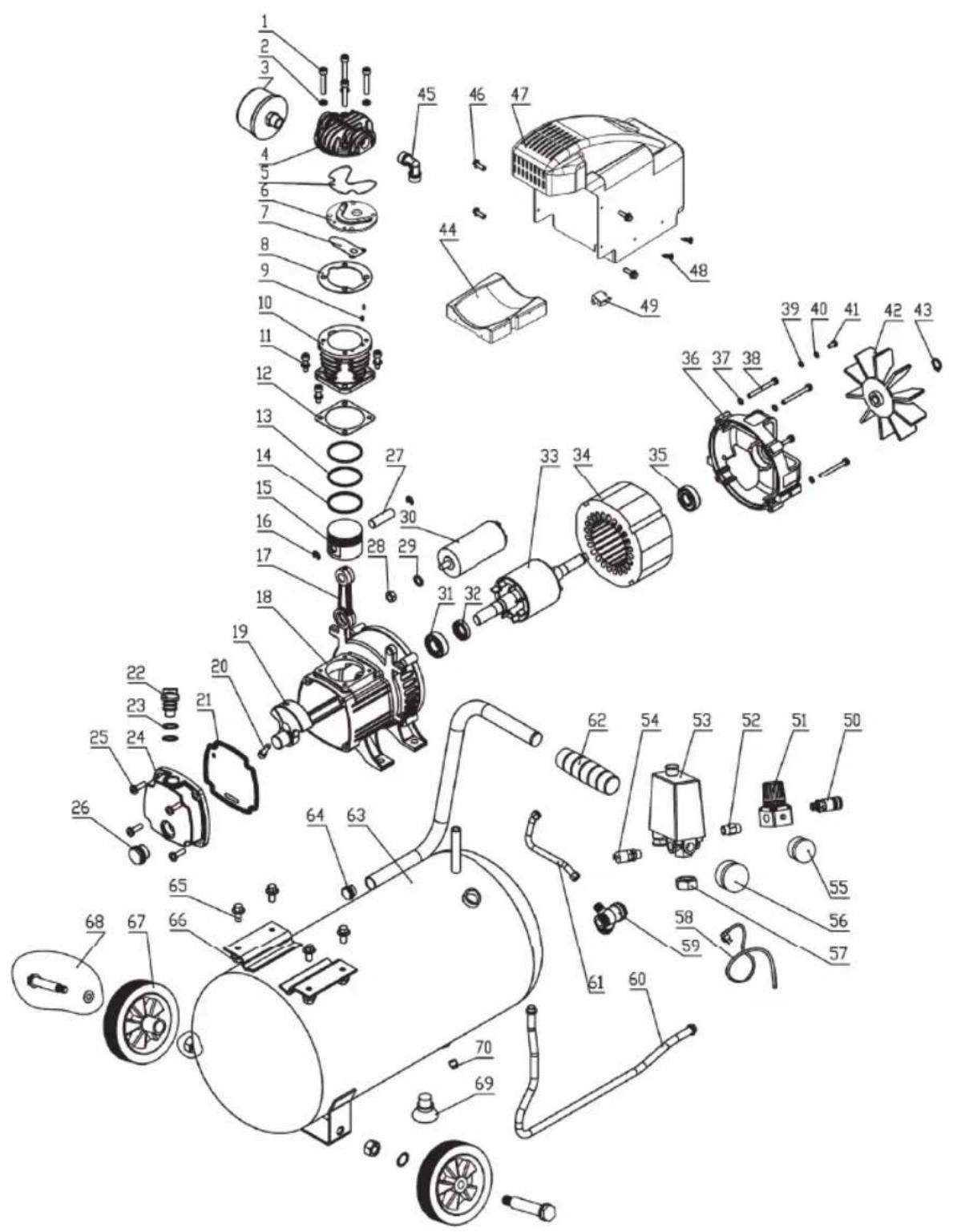
Exploded view
CE
DECLARATION OF CONFORMITY CRM1045 - COMPRESSOR
(EN) We declare under our sole responsibility that this product is in conformity with directive 2011/65/EU of the European parliament and of the council of 8 June on the restriction of the use of certain hazardous substances in electrical and electronic equipment is in conformity and accordance with the following standards and regulations:
(DE) Der Hersteller erklärt eigenverantwortlich, dass这点 Produkt der Direktive 2011/65/EU des Europäischen Parlaments und des Rats vom 8. Juni 2011 über die Einschränkung der Anwendung von bestimmten gefährlichen Stoffen in elektrischen und elektronischen Geräten entspricht. den folgenden Standards und Vorschriften entspricht:
(NL) Wij verwlaren onder onsone volledige verantwoordelijkeid dat dit product voldoet aan de conform Richtlij 2011/65/EU van het Europees Parlement en de Raad van 8 Juni 2011 betreffende beperking van het gebruik van bepaalde gevaartlijke stoffen in elektrische en elektronische apparatusu er in overeenstem ming is met de volgende standaarden en reguleringen:
(FR) Nous déclarons sous notre seule responsabilité que ce produit est conforme aux standards et directives suivants: est conforme à la Directive 2011/65/EU du Parlement Européen et du Conseil du 8 juin 2011 concernant la limitation d'usage de certaines substances dangereuses dans l'équipment électrique et électronique.
(ES) Declaramos bajo esta exclusiva responsabilidad que este producto cumple con las siguientes normas y estandares de configuraciono: se enquirya conforme con la Directiva 2011/65/UE del Parliamento Europeo y del Consejo de 8 de junio de 2011 sobre la restriccion del uso de determinadas sustancias peligrosas en los equipos electricos y electronicos.
(PT) Declaramos por esta total responsabilià-de que este produit está em conformidade e cumpre as normas e regulamentações que se seguem: está em conformidade com a Directa 2011/65/EU do Parlamento Europeu e com o Conselho de 8 de Junho de 2011 no que respeita à restruição de'utilização de determinadas substancias perigosas existentes em equipamento eletrico e electrônicos.
(1T) Dichiariamo,除去la nostrasresponsabilita,chethispedottoeconformale normativeeai regolamenti segunti:ede conformale alla Diretta 2011/65/UE del Parlamento Europeo e del Consiglio dell'8 giugno 2011 sulla limitazione dell'uso di determinate sostenze pericolose nelle appearechichature eltriche ed eltroniche.
(SV) Vi garanterar pa eget ansvar alt denna produktu uppyfllor och foljer foljande standarder och bestammelser: uppyfler direktiv 2011/65/EU fran Europeiska parliamentet etch EG-radet fran den 8 Juni 2011 om begransingen av anvandning av farlia substanser i elektrisk och elektronisk uutrusting.
(FI) Vakuutamme yksinomaan omalla vastuillamme, etta tama tuote tayttaa seuraavat standardit ja sddokset: tayttta Euroopan parlementin ja neuvoston 8, kaskuuta 2011 paviym direktivin 2011/65/EU vaatimukset koskien vaarallisten aineiden kavton raiotista sahkojaelektronissaa laiteissa.
(NO) Vi erklaerer under vart eget ansvar at ditte produktel er i samsvar med folgende standarder og regler: er i samsvar med EU-direktivet 2011/65/EU fra Europaaparlamentet og Europa-radet, pr. 8 Juni 2011, om begrensning ibruken av visse farlige stoffer i elektrisk og elektronisk ulstyr.
(DA) Vi erkräuter under egel ansvar, at dette produit er i overensstammelse med fällende standarder og bestemmelser: er i overensstammelse med direktiv 2011/65/EU fra Europa-Parliamentet og Rådet af 8. Juni 2011 om begrønsning af anvendelsen af visse farlige stoffer i elektrik og elektronisk udstr.
(HU) Felelssegünk teljes tudataban kijelentjuk, hogy ez a termek teljes mertékben megfelel az alabbi szabványoknak és elöráskokn: je v souladu se smernici 2011/65/EU Evropského parlamentu a Rady EU ze dne 8. cervna 2011, ktera se týká omezeni použiti určitych nebezpečnchy latek v elektrickych a elektronickych zařěntenich.
(CS) Na nasi vlastni zodpovednost prohlasujeme, ze je tento vyrobek v souladu s naseledujicim standarda y normami: Je v sulade s nomou 2011/65/EU Europskeho parlementu a Rady z 8. Juna 2011 tykajucej sa obmedzenia pouzivania urc'tych nebepezcechn'yatok v elektrikkom a elektronickom vybaveni.
(SK) Vylasujeme na nasu vyhradnu zodpovednost, ze tento vyrobok je vzhode a sulade snasledujuciimi normami a predisipimi: Ye v sulade s normou 2011/65/EU Europa'ske ho parlementu a Rady z 8. juna 2011 tykajucej sa obmedzenia pouzivania urstichy nebepezychn latak v elektrikom a elektronikom vybaveni.
(SL) S polno odgovnostjo izjavljamo, da je ta izdelek v skladu in da odgovarja naslednjinm standardom terpredispom: je v skladu z direktvo 2011/65/EU Evropskega para-menta in Sveta z d8. junii 2011 o omejevanju uporabe dolocenih nevamih snovi v elektricni in elektronski opremi.
(PL) Deklarjemyi na wlasna odopiewzialnośc, ze ten produkt spelniwa wymiqa zawarte w nastepujacych nomach i przyepsich: jest godny z Dyrektwy 2011/65/EU Parla. mentu Europejskiego i Rady z dnia 8 czerwca 2011 r. w sprawe ogranizcnia stosowanie nektórch niebeźpiecznychsubstcj w sprinkle elektrycznym i elektronicznym.
(LT) Prisiimdami visa alsakomybe deklaruojame, kad sis gaminys atilinka zemiau paminétus standartus arba nuostatus: atilinka 2011 m. birželio 8 d. Europos Parliamento ir Tarybos direktyva 2011/65/EB del tam tikru pavojingu medziagu naudoijmo elektrós ir elektronínejie irangoi apribojimo.
(LV) Ir atbiłsəa Etiropas Parliamenta un Padomes 2011. gada 8. jūnja Direktivai 2011/65/ES par dazu bistamu vielu izmantošanas iroberžošanu elektriskās un elektronikas ekjartās.
(ET) Agpalvojam ar visu atibldbu, ka sis produits ir saskana un atbilst sekjoSiem standarien um nolikumim: ir atbilstoia Eiropas Parliamenta un Padomes 2011. gada 8. junja Direktivai 2011/65/ES par da zu bistamu villi izmantoisanas ierobezoisanu elektriskas un elektroniskas iekartas.
(RO) Declaram prin aceasta cu raspundenera deplina ca produsul acesta this in conformate du urmatoleare standardae sau directive: este in conformitate cu Directiva 2011/65/UE a Parliamentului Europeana gi Consiliului din 8 junie 2011 cu privire la interzecerea utilizari anumitur substante periculoase la echipamentele electrice si elelectronice.
(HR) Izjavljemo pod vaslitom odgovroMsu da je stojem ukladan sa slijedesim standardima ill standardiziranim dokumentima i u skladu sa odredbama: usklaedeno s Direktivom 2011/65/EU europskog parliamenta i vija cizdanom 8. lipna 2011. oograničeniu koristenia odrešenih opasnih vari u elektrćnoj i elektronickovi proremi.
(SRL)Pod punom odgovronscu izjavljume da je usaglasen sa sledecim standardima li normama: usaglasen sa direktivom 2011/65/EU Evropskog parlamenta i Saveta od 8.juna.2011. godine za restrkciju upotrebe odredenih opasnih materija u elektricnoj i elektronskoj opremi.
(RO) NIO.CBOKOTBCTBEHOHCTB 3AEBNMO, CTO DAHNHOI DEJINIO COOTBCTBYET CNEUYUOM CTANHAPTAM N HOPMAMCOTBCTYRETBPOEBAHIM DIAPEKTNIBI 2011/65/EU Ebponeckoro napnameHTa n cobetaTg 8 mJOHA 2011 r. no ORPAHCHENIO KNObTOBAHNI ONPDEJEENHBx ONAChBX BELCECTB 3AIEKTPNeCKOM I ANEKTPOHHOMO6OBpODAHON
(UK) Na CBOBn BAnchy BiNIOAbIbHcT 3aBnHEMo, UO dahe ObnDAHHa BiINOBiDaC HACTYNNB CTANdAPTAM I HOPMTBAM: 3aD0BONBLHBEBMOR DmEKeTHMBA 2011/65/ CC CaponeeBckoro NaplanMeHTy Ta PaDi N B 8epehBa 2011 pOka HYo bOmekeHH BIKOPNCTAHHHI DEAHXN He63neuHnx PEOBHN B ENEKTPVHOMY TA ENEKTPHOHOMY O6bNDAHHHI.
EN1012-1, EN 60204-1, EN61000-6-1, EN61000-6-3, EN61000-3-2, EN61000-3-3
2011/65/EU, 2005/88/EC, 2014/29/EU, 2000/14/EC
2006/42/EC, 2014/35/EU, 2014/30/EU, 2012/19/EU
Zwolle, 01-01-2018
H.G.FRosberg
CEO FERM B.V.
FERM B.V. - Lingenstraat 6 - 8028 PM - Zwolle - The Netherlands


- Contents
- MACHINE DETAILS
- Technical specifications
- Product information
- Fig. A
- SAFETY INSTRUCTIONS
- Explanation of symbols
- Special safety instructions
- Electrical safety
- Earthing regulations
- Power supply
- USE
- Installation
- Filling the compressor with oil.
- Installing the air filters.
- Starting up
- Adjusting the operating pressure
- Fig. 14
- MAINTENANCE
- Malfunction
- Air loss
- The compressor will not start
- The compressor does not shut off
- Cleaning
- Drain the tank
- Clean the air filter
- Replacing/topping up oil
- Faults
- ENVIRONMENT
- WARRANTY
- KOMPRESSOR 1.5PS - 1100W - 24L
- Specifications techniques
- BEZPECNOSTNL POKNY
- Vyznam symbolu
- TEXHIUHE OBCIyROBYAHHH
- Komnpecop He BmmkaTbcra
- OuHnHn
- Дренихбaka
- Ynctka nobitpyHoro qinbtpa
- 3aHa/0nBaHHMa
- 360iBpo6oTi
- HABKOJIINSHCCEPEIOBNUe
- Spare parts list
- CE
- DECLARATION OF CONFORMITY CRM1045 - COMPRESSOR
Brand : Ferm
Model : CRM1045
Category : Compressor