
L DN 9850 FL PIR DE 3925 - Lighting BRENNENSTUHL - Free user manual and instructions
Find the device manual for free L DN 9850 FL PIR DE 3925 BRENNENSTUHL in PDF.
| Brand | Brennenstuhl |
| Model | L DN 9850 FL PIR DE 3925 |
| Product type | Compact LED floodlight with motion detector |
| Use | Indoor and outdoor, fixed installation |
| Power | 50 W (98 x 0.5 W) |
| Rated voltage | 230 V~ 50/60 Hz |
| Rated current | 0.22 A |
| Power factor | > 0.9 |
| Protection class | I |
| Protection rating | IP54 |
| Dimensions (L x W x H) | 290 x 276.5 x 40.5 mm |
| Weight | 2.0 kg |
| Maximum projected area | 0.05 m² |
| Detector type | Passive infrared sensor (PIR) |
| Detector range | Up to 12 m / 90° (horizontal) |
| Adjustable lighting duration | 10 seconds to 5 minutes |
| Adjustable brightness threshold | 0 - 2000 lux |
| Beam angle | 100° (as shown) |
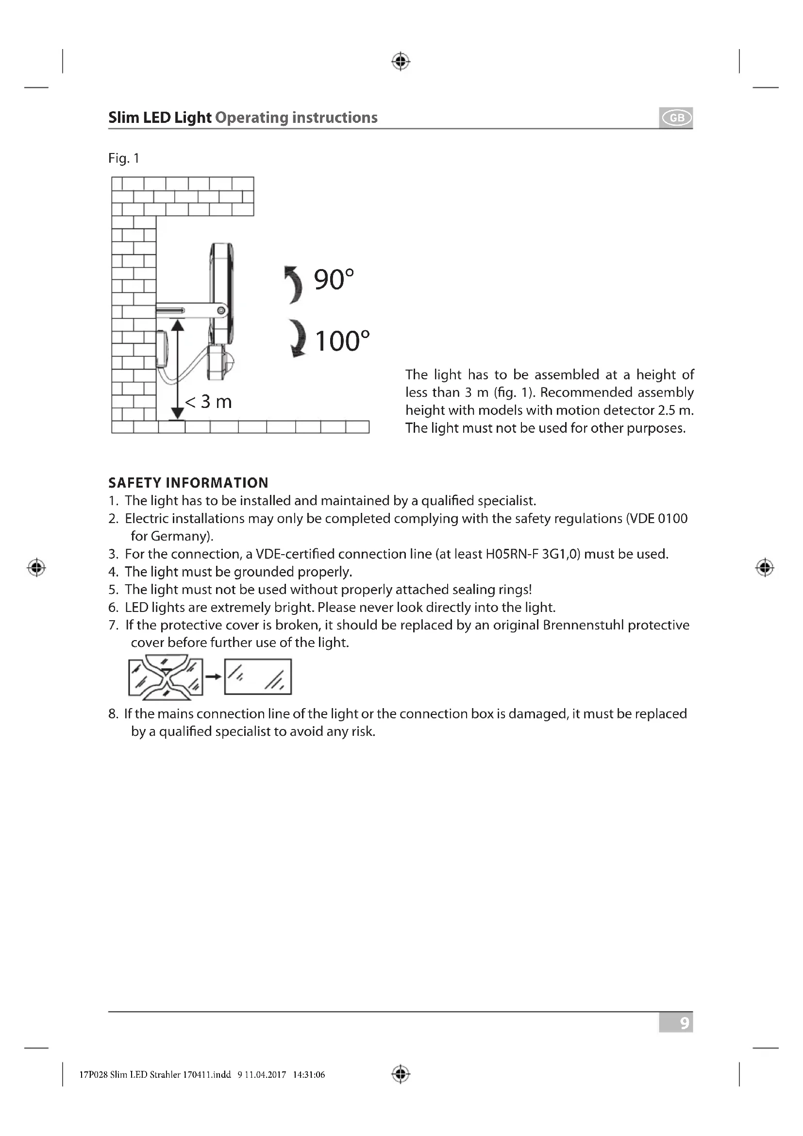
| Recommended installation height | ≤ 3 m (2.5 m with detector) |
| Connection cable | H05RN-F 3G1.0 minimum |
| Sealing gasket material | Dimensions: 250.8 x 185.8 x 4 mm |
| Maintenance | No maintenance-required components; clean with a dry or slightly damp cloth |
| Repairability | Replacement of the LED system only by the manufacturer or an authorized technician |
| Safety | Do not look directly into the beam; installation by a qualified professional; mandatory grounding |
Frequently Asked Questions - L DN 9850 FL PIR DE 3925 BRENNENSTUHL
User questions about L DN 9850 FL PIR DE 3925 BRENNENSTUHL
0 question about this device. Answer the ones you know or ask your own.
Ask a new question about this device
Download the instructions for your Lighting in PDF format for free! Find your manual L DN 9850 FL PIR DE 3925 - BRENNENSTUHL and take your electronic device back in hand. On this page are published all the documents necessary for the use of your device. L DN 9850 FL PIR DE 3925 by BRENNENSTUHL.
USER MANUAL L DN 9850 FL PIR DE 3925 BRENNENSTUHL
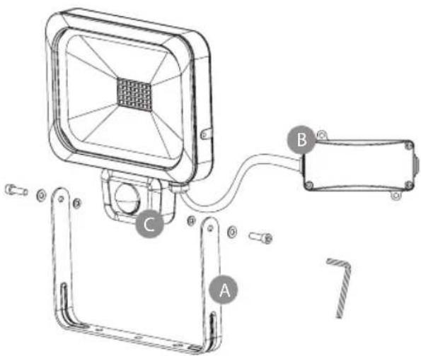
Abb. 3
GB Operating instructions Slim LED Light
L DN 2810 FL DE 3925 L DN 2810 FL PIR DE 3925 L DN 5630 FL DE 3925 L DN 5630 FL PIR DE 3925 L DN 9850 FL DE 3925 L DN 9850 FL PIR DE 3925
Attention: Before assembly of the light, please carefully read the operating instructions and store them at a proper location!
TECHNICAL DATA
Protection class: I
IP class: IP 54
Nominal voltage: 230 V\~ 50/60 Hz
Power factor: > 0.9
| Type: Power: Cur- | rent: | Motion detector: | Dimensions of protective cover: | Dimensions: Weight: max. | projected area: | ||
| L DN 2810 FL DE 3925 | 10 W(28 x 0.36 W) | 0.045 A | no | 124.2 x 90,2 x 4 mm | 136 x 146.5 x 40.5 mm | 0.43 kg | 0.01 m^2 |
| L DN 2810 FL PIR DE 3925 | 10 W(28 x 0.36 W) | 0.045 A | yes | 124.2 x 90,2 x 4 mm | 166 x 146.5 x 42.5 mm | 0.49 kg | 0.01 m^2 |
| L DN 5630 FL DE 3925 | 30 W(56 x 0.5 W) | 0.13 A | no | 201.6 x 146.6 x 4 mm | 202 x 231 x 35 mm | 1.25 kg | 0.03 m^2 |
| L DN 5630 FL PIR DE 3925 | 30 W(56 x 0.5 W) | 0.13 A | yes | 201.6 x 146.6 x 4 mm | 252 x 231 x 40.5 mm | 1.37 kg | 0.03 m^2 |
| L DN 9850 FL DE 3925 | 50 W(98 x 0.5 W) | 0.22 A | no | 250.8 x 185.8 x 4 mm | 235 x 276.5 x 40 mm | 1.92 kg | 0.05 m^2 |
| L DN 9850 FL PIR DE 3925 | 50 W(98 x 0.5 W) | 0.22 A | yes | 250.8 x 185.8 x 4 mm | 290 x 276.5 x 40.5 mm | 2.0 kg | 0.05 m^2 |
This high-power LED light is suitable for indoor and outdoor lighting purposes and for fixed assembly.
Fig. 1
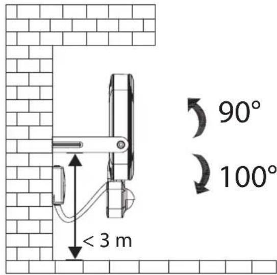
The light has to be assembled at a height of less than 3 m (fig. 1). Recommended assembly height with models with motion detector 2.5 m. The light must not be used for other purposes.
SAFETY INFORMATION
- The light has to be installed and maintained by a qualified specialist.
- Electric installations may only be completed complying with the safety regulations (VDE 0100 for Germany).
- For the connection, a VDE-certified connection line (at least H05RN-F 3G1,0) must be used.
- The light must be grounded properly.
- The light must not be used without properly attached sealing rings!
- LED lights are extremely bright. Please never look directly into the light.
- If the protective cover is broken, it should be replaced by an original Brennenstuhl protective cover before further use of the light.
- If the mains connection line of the light or the connection box is damaged, it must be replaced by a qualified specialist to avoid any risk.


ASSEMBLY AND CONNECTION TO POWER SUPPLY
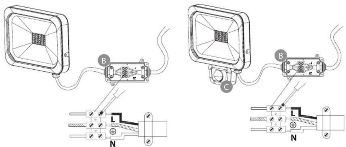
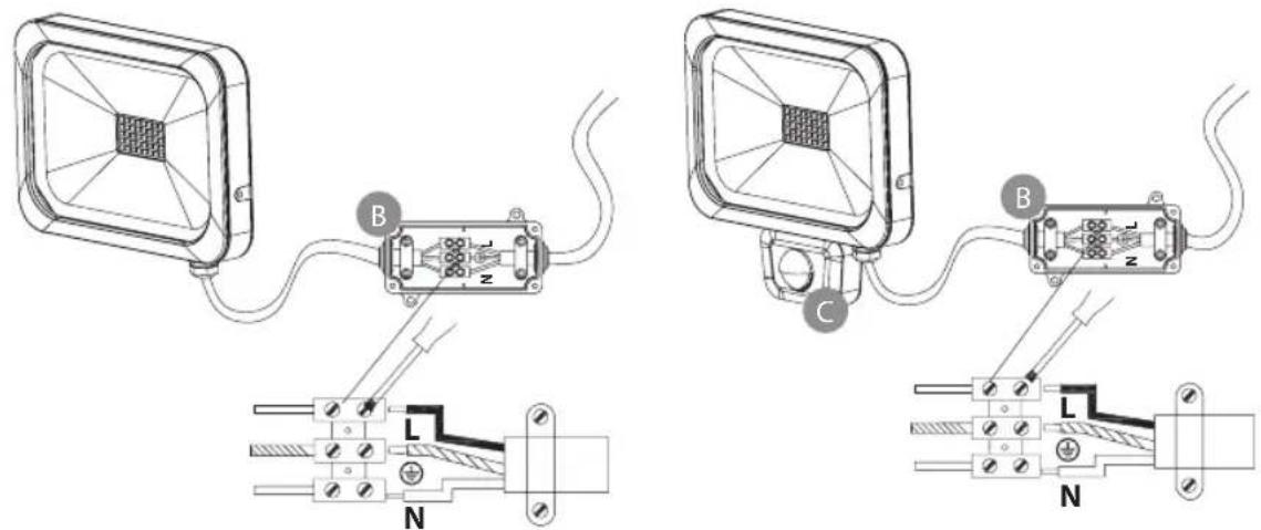
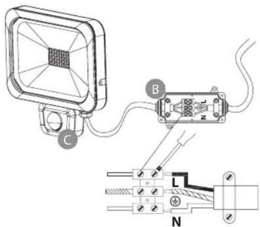
Holding bracket A, connection box B, motion sensor C
Fig. 2
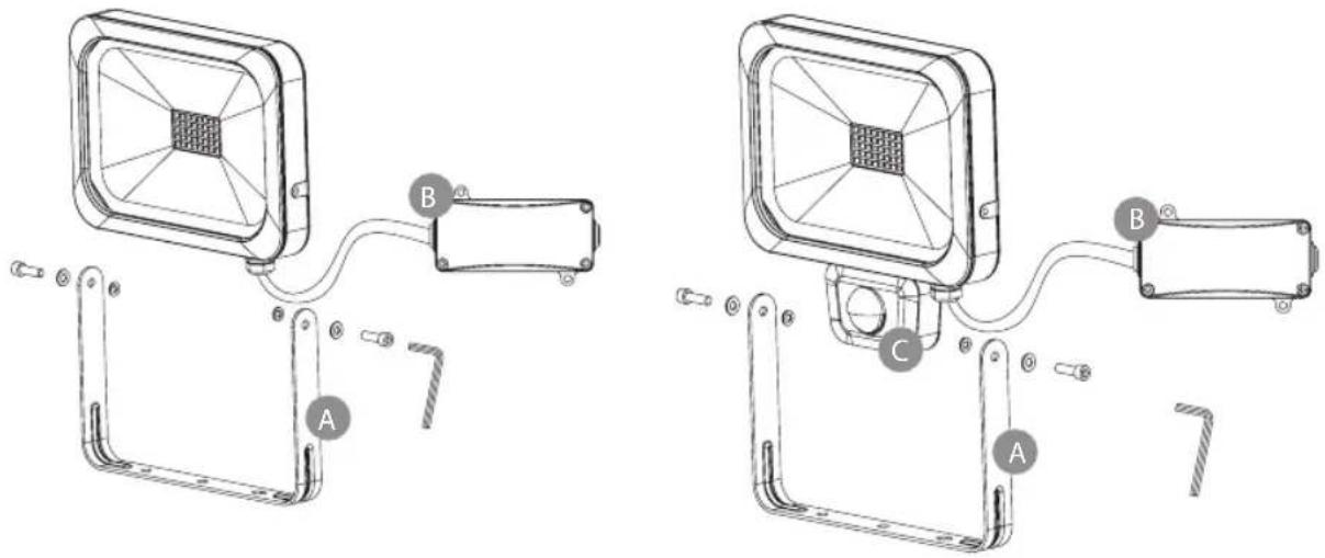
Fig. 3
- Before the installation, always switch off the voltage supply.
- Assembly position: The light should ideally be fastened by means of the wall bracket.
- Remove the holding bracket from the light (fig. 2).
- Mark the position of the bore holes for fastening the mounting bracket and bore corresponding holes into the wall. Fasten the bracket at the wall using suitable screws.
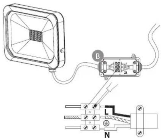
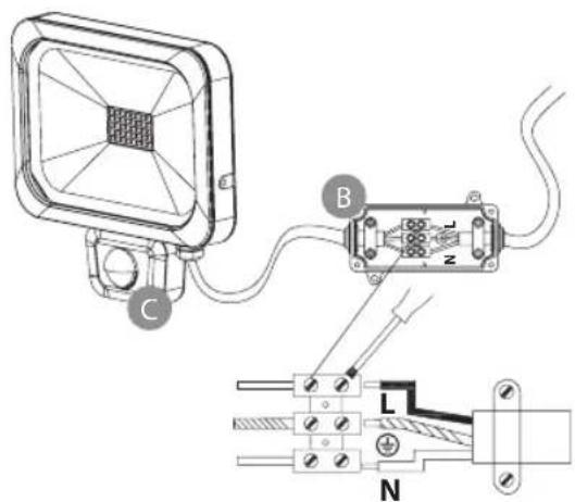
- Open the pre-assembled connection box.
- Lead the connection line through the cable entry provided with a seal and connect it to the screw terminal according to fig. 3 (N = blue cable, ⏚ = green/yellow cable, L = brown cable).
- Make sure that the connection line is sufficiently fixed by the tension relief.
- Screw-fix the cover to the connection box. Ensure correct seat of the seal.
- Fasten the light at the holding bracket.
- Adjust the desired position of the light and fasten the screws.
FUNCTIONAL DESCRIPTION
(only for versions with motion sensor)
This light is equipped with an infrared sensor. It is switched on automatically if the sensor detects motion in the environment.
If possible, do not direct the motion sensor at swimming pools, heating air exhausts, air conditioning units or objects which are exposed to major temperature fluctuations. Avoid directing the motion sensor at trees or bushes or at places which could be frequently visited by pets. The motion sensor can be horizontally rotated to the right and to the left.
When mounting the light remember that the motion sensor will react most sensitively to motions crossing its field of detection from one side to the other and least sensitively to motions directly approaching the unit.
ADJUSTING THE MOTION SENSOR
Fig. 4
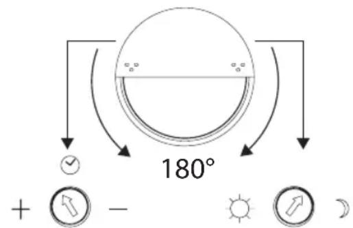
10 ± 5 sec. - 5 ± 1 min. 0 - 2000 LUX
Rotate the cover of the motion sensor by 180^ downwards; two controllers will appear (see fig. 4).
Time adjustment (clock symbol, left):
Using this controller, you can select any switch-on time between approx. 10 seconds and 5 minutes after the last motion was detected. Rotating the TIME controller clockwise decreases the time period, rotating it counterclockwise increases it.
Light adjustment (sun and moon symbol, right):
The light adjustment determines from which brightness level the sensor will switch on the light. The (★) position indicates that the sensor works by day and at night, in (C) position, the sensor will only work at night. To adjust the sensor, wait until the desired ambient brightness is reached. Completely rotate the light adjustment controller to the (C) symbol. Slowly rotate the controller in the direction of the (★) symbol until the light is switched on by the motion.
The light will now be activated from the set brightness when a motion is detected.
Motion sensor: passive infrared sensor
Detection range: up to 12 m/up to 90° (horizontal)
Time adjustment: approx. 10 sec. to 5 min.
Ambient brightness: 0 – 2000 Lux
MAINTENANCE
Attention: The LED light does not contain components that require maintenance.
The LED light source of this light must only be replaced by the manufacturer, a service technician sent by the manufacturer, or by another person with similar qualification.
Never open the light when the mains plug is still connected to the mains.
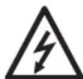
Caution: Risk of fatal injury from electrical current!
CLEANING
Do not use solvents, caustic cleaning agents or similar products. Only use a dry or slightly moistened cloth for cleaning.
DISPOSAL
Dispose of electric appliances in an environmentally friendly manner! Electric appliances must not be disposed of in household waste!
The European Directive 2012/19/EU on Waste Electrical and Electronic Equipment rules that used electric appliances should be collected separately and recycled in an environmentally friendly manner.
For possibilities of disposal of the used appliance, please contact your local or municipal administration.
Addresses
Illustration 3
Vermogensfactor: > 0.9
| Type: Vermogen: Stroom: Bewe- | gings-sensor: | Afmetingen be-schermingsplaat: | Afmetingen: Gewicht: max. | geproj-jecteerdoppervlak: | |||
| L DN 2810 FLDE 3925 | 10 W(28 x 0,36 W) | 0,045 A nee 124,2 x 90,2 x 4 mm | 136 x 146,5 x 40,5 mm | 0,43 kg 0,01 m^2 | |||
| L DN 2810 FLPIR DE 3925 | 10 W(28 x 0,36 W) | 0,045 A ja 124,2 x 90,2 x 4 mm | 166 x 146,5 x 42,5 mm | 0,49 kg 0,01 m^2 | |||
| L DN 5630 FLDE 3925 | 30 W(56 x 0,5 W) | 0,13 A nee 201,6 x 146,6 x 4 mm | 202 x 231 x 35 mm | 1,25 kg 0,03 m^2 | |||
| L DN 5630 FLPIR DE 3925 | 30 W(56 x 0,5 W) | 0,13 A ja 201,6 x 146,6 x 4 mm | 252 x 231 x 40,5 mm | 1,37 kg 0,03 m^2 | |||
| L DN 9850 FLDE 3925 | 50 W(98 x 0,5 W) | 0,22 A | nee | 250,8 x 185,8 x 4 mm | 235 x 276,5 x 40 mm | 1,92 kg | 0,05 m^2 |
| L DN 9850 FLPIR DE 3925 | 50 W(98 x 0,5 W) | 0,22 A | ja | 250,8 x 185,8 x 4 mm | 290 x 276,5 x 40,5 mm | 2,0 kg | 0,05 m^2 |
Afb. 3

FUNCTIONELE BESCHRIJVING
Illustr. 3

Fig. 3


Rys. 3


- GB Operating instructions Slim LED Light
- TECHNICAL DATA
- SAFETY INFORMATION
- ASSEMBLY AND CONNECTION TO POWER SUPPLY
- FUNCTIONAL DESCRIPTION
- ADJUSTING THE MOTION SENSOR
- Time adjustment (clock symbol, left):
- Light adjustment (sun and moon symbol, right):
- MAINTENANCE
- CLEANING
- DISPOSAL
- Dispose of electric appliances in an environmentally friendly manner! Electric appliances must not be disposed of in household waste!
- Addresses
- FUNCTIONELE BESCHRIJVING
Brand : BRENNENSTUHL
Model : L DN 9850 FL PIR DE 3925
Category : Lighting