USER MANUAL GSB 18V55 Professional BOSCH
natural_image
Two Bosch electric drillers with black and gray casing, no visible text or symbols on the devices themselves.

Robert Bosch Power Tools GmbH
70538 Stuttgart
GERMANY
www.bosch-pt.com
1609 92A 5C8 (2019.07) AS / 228

1 609 92A 5C8
GSR | GSB Professional
18V-55

BOSCH
WARNING
Read all safety warnings, instructions, illustrations and specifica-
tions provided with this power tool. Failure to follow all instructions listed below may result in electric shock, fire and/or serious injury.
Save all warnings and instructions for future reference.
The term "power tool" in the warnings refers to your mains-operated (corded) power tool or battery-operated (cordless) power tool.
Work area safety
▶ Keep work area clean and well lit. Cluttered or dark areas invite accidents.
▶ Do not operate power tools in explosive atmospheres, such as in the presence of flammable liquids, gases or dust. Power tools create sparks which may ignite the dust or fumes.
▶ Keep children and bystanders away while operating a power tool. Distractions can cause you to lose control.
Electrical safety
▶ Power tool plugs must match the outlet. Never modify the plug in any way. Do not use any adapter plugs with
earthed (grounded) power tools. Unmodified plugs and matching outlets will reduce risk of electric shock.
▶ Avoid body contact with earthed or grounded surfaces, such as pipes, radiators, ranges and refrigerators. There is an increased risk of electric shock if your body is earthed or grounded.
▶ Do not expose power tools to rain or wet conditions. Water entering a power tool will increase the risk of electric shock.
▶ Do not abuse the cord. Never use the cord for carrying, pulling or unplugging the power tool. Keep cord away from heat, oil, sharp edges or moving parts.
Damaged or entangled cords increase the risk of electric shock.
▶ When operating a power tool outdoors, use an extension cord suitable for outdoor use. Use of a cord suitable for outdoor use reduces the risk of electric shock.
▶ If operating a power tool in a damp location is unavoidable, use a residual current device (RCD) protected supply. Use of an RCD reduces the risk of electric shock.
Personal safety
▶ Stay alert, watch what you are doing and use common sense when operating a power tool. Do not use a power tool while you are tired or under the influence of drugs, alcohol or medication. A moment of inattention while operating power tools may result in serious personal injury.
▶ Use personal protective equipment. Always wear eye protection. Protective equipment such as a dust mask, non-skid safety shoes, hard hat or hearing protection used for appropriate conditions will reduce personal injuries.
▶ Prevent unintentional starting. Ensure the switch is in the off-position before connecting to power source and/or battery pack, picking up or carrying the tool. Carrying power tools with your finger on the switch or energising power tools that have the switch on invites accidents.
Remove any adjusting key or wrench before turning the power tool on. A wrench or a key left attached to a rotating part of the power tool may result in personal injury.
▶ Do not overreach. Keep proper footing and balance at all times. This enables better control of the power tool in unexpected situations.
▶ Dress properly. Do not wear loose clothing or jewellery. Keep your hair and clothing away from moving parts. Loose clothes, jewellery or long hair can be caught in moving parts.
If devices are provided for the connection of dust extraction and collection facilities, ensure these are connected and properly used. Use of dust collection can reduce dust-related hazards.
▶ Do not let familiarity gained from frequent use of tools allow you to become complacent and ignore tool
safety principles. A careless action can cause severe injury within a fraction of a second.
▶ Do not force the power tool. Use the correct power tool for your application. The correct power tool will do the job better and safer at the rate for which it was designed.
▶ Do not use the power tool if the switch does not turn it on and off. Any power tool that cannot be controlled with the switch is dangerous and must be repaired.
▶ Disconnect the plug from the power source and/or remove the battery pack, if detachable, from the power tool before making any adjustments, changing accessories, or storing power tools. Such preventive safety measures reduce the risk of starting the power tool accidentally.
▶ Store idle power tools out of the reach of children and do not allow persons unfamiliar with the power tool or these instructions to operate the power tool. Power tools are dangerous in the hands of untrained users.
- Maintain power tools and accessories. Check for misalignment or binding of moving parts, breakage of parts and any other condition that may affect the power tool's operation. If damaged, have the power tool repaired before use. Many accidents are caused by poorly maintained power tools.
▶ Keep cutting tools sharp and clean. Properly maintained cutting tools with sharp cutting edges are less likely to bind and are easier to control.
▶ Use the power tool, accessories and tool bits etc. in accordance with these instructions, taking into account the working conditions and the work to be performed. Use of the power tool for operations different from those intended could result in a hazardous situation.
▶ Keep handles and grasping surfaces dry, clean and free from oil and grease. Slippery handles and grasping surfaces do not allow for safe handling and control of the tool in unexpected situations.
▶ Recharge only with the charger specified by the manufacturer. A charger that is suitable for one type of battery pack may create a risk of fire when used with another battery pack.
▶ Use power tools only with specifically designated battery packs. Use of any other battery packs may create a risk of injury and fire.
When battery pack is not in use, keep it away from other metal objects, like paper clips, coins, keys, nails, screws or other small metal objects, that can make a connection from one terminal to another. Shorting the battery terminals together may cause burns or a fire.
▶ Under abusive conditions, liquid may be ejected from the battery; avoid contact. If contact accidentally occurs, flush with water. If liquid contacts eyes, addi-
14 | English
tionally seek medical help. Liquid ejected from the battery may cause irritation or burns.
▶ Do not use a battery pack or tool that is damaged or modified. Damaged or modified batteries may exhibit unpredictable behaviour resulting in fire, explosion or risk of injury.
▶ Do not expose a battery pack or tool to fire or excessive temperature. Exposure to fire or temperature above 130^ C may cause explosion.
▶ Follow all charging instructions and do not charge the battery pack or tool outside the temperature range specified in the instructions. Charging improperly or at temperatures outside the specified range may damage the battery and increase the risk of fire.
Service
▶ Have your power tool serviced by a qualified repair person using only identical replacement parts. This will ensure that the safety of the power tool is maintained.
▶ Never service damaged battery packs. Service of battery packs should only be performed by the manufacturer or authorized service providers.
Safety instructions for all operations GSB
▶ Wear ear protectors when impact drilling. Exposure to noise can cause hearing loss.
GSB / GSR
▶ Hold the power tool by insulated gripping surfaces, when performing an operation where the cutting accessory or fasteners may contact hidden wiring. Cutting accessory or fasteners contacting a "live" wire may make exposed metal parts of the power tool "live" and could give the operator an electric shock.
Safety instructions when using long drill bits
▶ Never operate at higher speed than the maximum speed rating of the drill bit. At higher speeds, the bit is likely to bend if allowed to rotate freely without contacting the workpiece, resulting in personal injury.
▶ Always start drilling at low speed and with the bit tip in contact with the workpiece. At higher speeds, the bit is likely to bend if allowed to rotate freely without contacting the workpiece, resulting in personal injury.
▶ Apply pressure only in direct line with the bit and do not apply excessive pressure. Bits can bend causing breakage or loss of control, resulting in personal injury.
Additional safety warnings
▶ Hold the power tool securely. When tightening and loosening screws be prepared for temporarily high torque reactions.
- Secure the workpiece. A workpiece clamped with clamping devices or in a vice is held more secure than by hand.
▶ Use suitable detectors to determine if there are hidden supply lines or contact the local utility company for assistance. Contact with electric cables can cause fire and electric shock. Damaging gas lines can lead to explosion. Breaking water pipes causes property damage.
▶ Always wait until the power tool has come to a complete stop before placing it down. The application tool can jam and cause you to lose control of the power tool.
In case of damage and improper use of the battery, vapours may be emitted. The battery can set alight or explode. Ensure the area is well ventilated and seek medical attention should you experience any adverse effects. The vapours may irritate the respiratory system.
▶ Do not open the battery. There is a risk of short-circuiting.
The battery can be damaged by pointed objects such as nails or screwdrivers or by force applied externally. An internal short circuit may occur, causing the battery to burn, smoke, explode or overheat.
▶ Only use the battery with products from the manufacturer. This is the only way in which you can protect the battery against dangerous overload.

Protect the battery against heat, e.g. against continuous intense sunlight, fire, dirt, water and moisture. There is a risk of explosion and short-circuiting.
▶ Switch the power tool off immediately if the application tool becomes blocked. Be prepared for high torque reactions which cause kickback. The application tool becomes blocked when it becomes jammed in the workpiece or when the power tool becomes overloaded.
Product Description and Specifications

Read all the safety and general instructions. Failure to observe the safety and general instructions may result in electric shock, fire and/or serious injury.
Please observe the illustrations at the beginning of this operating manual.
Intended use
The power tool is intended for driving and loosening screws and for drilling in wood, metal, ceramic and plastic. The GSB is also designed for impact drilling in brick, masonry and stone.
Product features
The numbering of the product features refers to the diagram of the power tool on the graphics page.
(1) Tool holder
(2) Keyless chuck
(3) Torque presetting ring
English | 15
(4) Mode selector switch (GSB)
(5) Gear selector switch
(6) Belt clip
(7) Battery ^A)
(8) Battery release button ^A
(9) Worklight (LED)
(10) Rotational direction switch
(11) On/off switch
(12) Bit holder ^A)
(13) Handle (insulated gripping surface)
(14) Battery charge indicator ^A)
(15) Button for battery charge indicator ^A)
A) Accessories shown or described are not included with the product as standard. You can find the complete selection of accessories in our accessories range.
Technical data
| Cordless Drill/DriverCombination Cordless Drill | GSR 18V-55 GSB 18V-55 |
| Article number | | 3 601 JH5 2.. 3 601 JH5 3.. |
| Rated voltage V= 18 18 | | | |
| No-load speed ^A) | | | |
| - First gear min | -1 | 0-460 0-460 |
| - Second gear min | -1 | 0-1,800 0-1,800 |
| Impact rate ^A) | min ^-1 | -0-27,000 |
| Max. torque hard/soft screwdriving applications ^A) | Nm 55/28 55/28 | |
| Max. drilling diameter (first/second gear) | | | |
| - Wood mm 35 35 | | | |
| - Steel mm 13 13 | | | |
| - Masonry mm - 13 | | | |
| Chuck capacity mm | 1.5-13 | 1.5-13 | |
| Screw diameter max. | mm 10 10 | |
| Weight according to EPTA-Procedure 01:2014 ^A) | kg | 1.4-2.4 | 1.4-2.5 |
| Permitted ambient temperature | | | |
| - during charging | °C | 0 to +35 | 0 to +35 |
| - during operation ^B) and during storage | °C | -20 to +50 | -20 to +50 |
| Recommended batteries | | GBA 18V...ProCORE18V... | GBA 18V...ProCORE18V... |
| Recommended chargers | | GAL 18...GAX 18...GAL 36... | GAL 18...GAX 18...GAL 36... |
A) Depends on battery in use
B) Limited performance at temperatures <0 °C
Noise/Vibration Information
| GSR 18V-55 | GSB 18V-55 |
| Noise emission values determined according to EN 62841-2-1. |
| Typically, the A-weighted noise level of the power tool is |
| Sound pressure level | dB(A) | 72.5 | 88 |
| Sound power level | dB(A) | 83.5 | 99 |
| Uncertainty K | dB | 5 | 5 |
| Wear hearing protection |
Vibration total values a_h (triax vector sum) and uncertainty K determined according to EN 62841-2-1.
16 | English
GSR 18V-55 GSB 18V-55
| Drilling in metal: |
| a_h | m/s2 | 2 | 1.5 |
| K | m/s2 | 1.5 | 1.5 |
| Impact drilling into concrete: |
| a_h | m/s2 | - | 11 |
| K | m/s2 | - | 1.5 |
The vibration level and noise emission value given in these instructions have been measured in accordance with a standardised measuring procedure and may be used to compare power tools. They may also be used for a preliminary estimation of vibration and noise emissions.
The stated vibration level and noise emission value represent the main applications of the power tool. However, if the power tool is used for other applications, with different application tools or is poorly maintained, the vibration level and noise emission value may differ. This may significantly increase the vibration and noise emissions over the total working period.
To estimate vibration and noise emissions accurately, the times when the tool is switched off or when it is running but not actually being used should also be taken into account. This may significantly reduce vibration and noise emissions over the total working period.
Implement additional safety measures to protect the operator from the effects of vibration, such as servicing the power tool and application tools, keeping their hands warm, and organising workflows correctly.
Assembly
Remove the battery from the power tool before carrying out work on the power tool (e.g. maintenance, changing tool, etc.). The battery should also be removed for transport and storage. There is risk of injury from unintentionally pressing the on/off switch.
Charging the Battery
▶ Use only the chargers listed in the technical data. Only these chargers are matched to the lithium-ion battery of your power tool.
Note: The battery is supplied partially charged. To ensure full battery capacity, fully charge the battery in the charger before using your power tool for the first time.
The lithium-ion battery can be charged at any time without reducing its service life. Interrupting the charging process does not damage the battery.
The lithium-ion battery is protected against deep discharge by the "Electronic Cell Protection (ECP)". When the battery is discharged, the power tool is switched off by means of a protective circuit: The application tool no longer rotates. Follow the instructions on correct disposal.
Removing the Battery
The battery (7) is equipped with two locking levels to prevent the battery from falling out when pushing the battery release button (8) unintentionally. As long as the battery is inserted in the power tool, it is held in position by means of a spring.
To remove the battery (7), press the release button (8) and pull the battery out of the power tool. Do not use force to do this.
Battery Charge Indicator
The green LEDs on the battery charge indicator (14) indicate the state of charge of the battery (7). For safety reasons, it is only possible to check the state of charge when the power tool has been stopped.
Press the battery charge indicator button (15) to show the state of charge. This is also possible when the battery is removed.
If no LED lights up after pressing the battery charge indicator button (15), the battery is defective and must be replaced.
Battery Model GBA 18V... (see figure D1)
| LEDs Capacity |
| 3× continuous green light 60–100 % |
| 2× continuous green light 30–60 % |
| 1× continuous green light 5–30 % |
| 3× flashing green light 0–5 % |
Battery Model ProCORE18V... (see figure D2)
| LEDs Capacity |
| 5× continuous green light 80–100 % |
| 4× continuous green light 60–80 % |
| 3× continuous green light 40–60 % |
| 2× continuous green light 20–40 % |
| 1× continuous green light 5–20 % |
| 1× flashing green light 0–5 % |
Remove the battery from the power tool before carrying out work on the power tool (e.g. maintenance, changing tool, etc.). The battery should also be removed for transport and storage. There is risk of injury from unintentionally pressing the on/off switch.
The drill spindle is locked when the on/off switch (11) is not pressed. This makes it possible to change the application tool in the drill chuck quickly, conveniently and easily.
Open the keyless chuck (2) by turning it in the direction of rotation ① until the tool can be inserted. Insert the tool.
Firmly tighten the keyless chuck (2) by turning it by hand in the direction of rotation ②. This will automatically lock the drill chuck.
Dust from materials such as lead-containing coatings, some wood types, minerals and metal can be harmful to one's health. Touching or breathing-in the dust can cause allergic reactions and/or lead to respiratory infections of the user or bystanders.
Certain dust, such as oak or beech dust, is considered carcinogenic, especially in connection with wood-treatment additives (chromate, wood preservative). Materials containing asbestos may only be worked by specialists.
- Provide for good ventilation of the working place.
- It is recommended to wear a P2 filter-class respirator.
Observe the relevant regulations in your country for the materials to be worked.
- Avoid dust accumulation at the workplace. Dust can easily ignite.
Operation
Starting Operation
Inserting the battery
Note: The use of batteries unsuitable for your power tool can lead to malfunctions or damage to the power tool.
Push the charged battery (7) into the base of the power tool from the front until the battery is securely locked.
The rotational direction switch (10) is used to change the rotational direction of the power tool. However, this is not possible while the on/off switch (11) is being pressed.
Right rotation: To drill and to drive in screws, press the rotational direction switch (10) through to the left stop.
Left Rotation: To loosen and unscrew screws and nuts, press the rotational direction switch (10) through to the right stop.
Setting the Operating Mode

Drilling
GSR
Set the torque presetting ring (3) to the "drilling" symbol.
GSB
Set the mode selector switch (4) to the "drilling" symbol.

Screwdriving
GSR
Set the torque presetting ring (3) to the required torque.
GSB
Set the mode selector switch (4) to the "screw-driving" symbol.

Impact drilling (GSB)
Set the mode selector switch (4) to the "impact drilling" symbol.
Switching on/off
To start the power tool, press and hold the on/off switch (11).
The LED (9) lights up when the on/off switch (11) is lightly or fully pressed, meaning that the work area is illuminated in poor lighting conditions.
To switch off the power tool, release the on/off switch (11).
Adjusting the Speed
You can adjust the speed of the power tool when it is on by pressing in the on/off switch (11) to varying extents.
A light pressure on the on/off switch (11) results in a low rotational speed. Increased pressure on the switch causes an increase in speed.
Preselecting torque (applies to screwdriving mode)
The torque presetting ring (3) can be used to pre-select the required torque in 20 stages. Once the set torque has been reached, the application tool will be stopped.
Mechanical gear selection
▶ Only operate the gear selector (5) when the power tool is not in use.
First gear:
Low speed range; for working with a large drilling diameter or for screwdriving.
Second gear:
High speed range; for working with a small drilling diameter.
▶ Always push the gear selector switch as far as it will go. Otherwise, the power tool may become damaged.
Temperature-dependent overload protection
When used as intended, the power tool cannot be overloaded. In the event of overloading or the temperature rising/falling outside the permitted operating temperature range, the speed will be reduced. The power tool will not run at full speed again until the permitted operating temperature has been reached.
Fully automatic spindle lock (Auto-Lock)
The drill spindle, and therefore the tool holder, are locked when the on/off switch (11) is not pressed.
This allows screws to be driven in even when the battery is discharged and enables the power tool to be used as a screwdriver.
18 | English
Practical advice
▶ Only apply the power tool to the screw when the tool is switched off. Rotating application tools can slip off.
Before screwing larger, longer screws into hard materials, it is advisable to pre-drill a pilot hole with the core diameter of the thread to approx. 2/3 of the screw length.
An auxiliary tool can be used to remove the screwdriver bit or universal bit holder.
Belt clip
You can use the belt clip (6) to hang the power tool on a belt, for example. You then have both hands free and the power tool is always at hand.
Maintenance and Service
Maintenance and Cleaning
Remove the battery from the power tool before carrying out work on the power tool (e.g. maintenance, changing tool, etc.). The battery should also be removed for transport and storage. There is risk of injury from unintentionally pressing the on/off switch.
▶ To ensure safe and efficient operation, always keep the power tool and the ventilation slots clean.
After-Sales Service and Application Service
Our after-sales service responds to your questions concerning maintenance and repair of your product as well as spare parts. You can find explosion drawings and information on spare parts at: www.bosch-pt.com
The Bosch product use advice team will be happy to help you with any questions about our products and their accessories.
In all correspondence and spare parts orders, please always include the 10-digit article number given on the nameplate of the product.
Great Britain
Robert Bosch Ltd. (B.S.C.)
P.O. Box 98
Broadwater Park
North Orbital Road
Denham Uxbridge
UB 9 5HJ
At www.bosch-pt.co.uk you can order spare parts or arrange the collection of a product in need of servicing or repair.
Tel. Service: (0344) 7360109
E-Mail: boschservicecentre@bosch.com
Ireland
Origo Ltd.
Unit 23 Magna Drive
Magna Business Park
City West
Dublin 24
Tel. Service: (01) 4666700
Fax: (01) 4666888
Australia, New Zealand and Pacific Islands
Robert Bosch Australia Pty. Ltd.
Power Tools
Locked Bag 66
Clayton South VIC 3169
Customer Contact Center
Inside Australia:
Phone: (01300) 307044
Fax: (01300) 307045
Inside New Zealand:
Phone: (0800) 543353
Fax: (0800) 428570
Outside AU and NZ:
Phone: +61 3 95415555
www.bosch-pt.com.au
www.bosch-pt.co.nz
Republic of South Africa
Customer service
Hotline: (011) 6519600
Gauteng - BSC Service Centre
35 Roper Street, New Centre
Johannesburg
Tel.: (011) 4939375
Fax: (011) 4930126
E-Mail: bsctools@icon.co.za
KZN - BSC Service Centre
Unit E, Almar Centre
143 Crompton Street
Pinetown
Tel.: (031) 7012120
Fax: (031) 7012446
E-Mail: bsc.dur@za.bosch.com
Western Cape - BSC Service Centre
Democracy Way, Prosperity Park
Milnerton
Tel.: (021) 5512577
Fax: (021) 5513223
E-Mail: bsc@zsd.co.za
Bosch Headquarters
Midrand, Gauteng
Tel.: (011) 6519600
Fax: (011) 6519880
E-Mail: rbsa-hq.pts@za.bosch.com
Transport
The contained lithium-ion batteries are subject to the Dangerous Goods Legislation requirements. The batteries are suitable for road-transport by the user without further restrictions.
When shipping by third parties (e.g.: by air transport or forwarding agency), special requirements on packaging and labelling must be observed. For preparation of the item being shipped, consulting an expert for hazardous material is required.
Dispatch battery packs only when the housing is undamaged. Tape or mask off open contacts and pack up the battery in such a manner that it cannot move around in the
packaging. Please also observe the possibility of more detailed national regulations.
Disposal

The machine, rechargeable batteries, accessories and packaging should be sorted for environmental-friendly recycling.

Do not dispose of power tools and batteries/rechargeable batteries into household waste!
Only for EU countries:
According to the Directive 2012/19/EU, power tools that are no longer usable, and according to the Directive 2006/66/EC, defective or used battery packs/batteries, must be collected separately and disposed of in an environmentally correct manner.
Battery packs/batteries:
Li-ion:
Please observe the notes in the section on transport (see "Transport", page 18).
Français
Robert Bosch (France) S.A.S.
Calle Robert Bosch No. 405
Bosch Service Center
Telegrafvej 3
2750 Ballerup
På www.bosch-pt.dk kan der online bestilles reservedele eller oprettes en reparations ordre.
Tlf. Service Center: 44898855
Fax: 44898755
E-Mail: vaerktoej@dk.bosch.com
Transport
Bosch Service Center
Telegrafvej 3
2750 Ballerup
Danmark
Tel.: (08) 7501820 (inom Sverige)
Fax: (011) 187691
Transport
Robert Bosch Sp. z o.o.
Bosch Service Center PT
K Vápence 1621/16
692 01 Mikulov
Service scule electrice
Strada Horia Măcelariu Nr. 30–34, sector 1
013937 Bucureşti
Service scule electrice
Strada Horia Măcelariu Nr. 30–34, sector 1
013937 Bucureşti, România
www.bosch-pt.com/bg/bg/
Транспортиране
Robert Bosch Morocco SARL
Sahba Technology Group
شارع مطار المثنى
بقداد
◀jā meaning (az) meaning (a)
natural_image
Technical line drawing of a mechanical housing or enclosure component (no text or symbols)
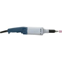
2 608 438 692
(L-BOXX 136)

natural_image
Technical line drawing of a mechanical housing or enclosure component (no text or symbols)
1 600 A00 2WA
natural_image
Technical line drawing of a mechanical housing component (no text or symbols)
1 600 A00 2WC
Licenses
Copyright © 2009 - 2013 ARM LIMITED
All rights reserved.
Redistribution and use in source and binary forms, with or without modification, are permitted provided that the following conditions are met:
- Redistributions of source code must retain the above copyright notice, this list of conditions and the following disclaimer.
- Redistributions in binary form must reproduce the above copyright notice, this list of conditions and the following disclaimer in the documentation and/or other materials provided with the distribution.
- Neither the name of ARM nor the names of its contributors may be used to endorse or promote products derived from this software without specific prior written permission.
THIS SOFTWARE IS PROVIDED BY THE COPYRIGHT HOLDERS AND CONTRIBUTORS "AS IS" AND ANY EXPRESS OR IMPLIED WARRANTIES, INCLUDING, BUT NOT LIMITED TO, THE IMPLIED WARRANTIES OF MERCHANTABILITY AND FITNESS FOR A PARTICULAR PURPOSE ARE DISCLAIMED. IN NO EVENT SHALL THE COPYRIGHT OWNER OR CONTRIBUTORS BE LIABLE FOR ANY DIRECT, INDIRECT, INCIDENTAL, SPECIAL, EXEMPLARY, OR CONSEQUENTIAL DAMAGES (INCLUDING, BUT NOT LIMITED TO, PROCUREMENT OF SUBSTITUTE GOODS OR SERVICES; LOSS OF USE, DATA, OR PROFITS; OR BUSINESS INTERRUPTION) HOWEVER CAUSED AND ON ANY THEORY OF LIABILITY, WHETHER IN CONTRACT, STRICT LIABILITY, OR TORT (INCLUDING NEGLIGENCE OR OTHERWISE) ARISING IN ANY WAY OUT OF THE USE OF THIS SOFTWARE, EVEN IF ADVISED OF THE POSSIBILITY OF SUCH DAMAGE.
Copyright © 2015, Infineon Technologies AG
All rights reserved.
Redistribution and use in source and binary forms, with or without modification, are permitted provided that the following conditions are met:
- Redistributions of source code must retain the above copyright notice, this list of conditions and the following disclaimer.
- Redistributions in binary form must reproduce the above copyright notice, this list of conditions and the following disclaimer in the documentation and/or other materials provided with the distribution.
- Neither the name of the copyright holders nor the names of its contributors may be used to endorse or promote products derived from this software without specific prior written permission.
THIS SOFTWARE IS PROVIDED BY THE COPYRIGHT HOLDERS AND CONTRIBUTORS "AS IS" AND ANY EXPRESS OR IMPLIED WARRANTIES, INCLUDING, BUT NOT LIMITED TO, THE IMPLIED WARRANTIES OF MERCHANTABILITY AND FITNESS FOR A PARTICULAR PURPOSE ARE DISCLAIMED. IN NO EVENT SHALL THE COPYRIGHT OWNER OR CONTRIBUTORS BE LIABLE FOR ANY DIRECT, INDIRECT, INCIDENTAL, SPECIAL, EXEMPLARY, OR CONSEQUENTIAL DAMAGES (INCLUDING, BUT NOT LIMITED TO, PROCUREMENT OF SUBSTITUTE GOODS OR SERVICES; LOSS OF USE, DATA, OR PROFITS; OR BUSINESS INTERRUPTION) HOWEVER CAUSED AND ON ANY THEORY OF LIABILITY, WHETHER IN CONTRACT, STRICT LIABILITY, OR TORT (INCLUDING NEGLIGENCE OR OTHERWISE) ARISING IN ANY WAY OUT OF THE USE OF THIS SOFTWARE, EVEN IF ADVISED OF THE POSSIBILITY OF SUCH DAMAGE.
CE
1
| de | EU-Konformitätserklärung | Wir erklären in alleiniger Verantwortung, dass die genannten Produkte allen einschlägigen Bestimmungen der nachfolgend aufgeführten Richtlinien und Verordnungen entsprechen und mit folgenden Normen übereinstimmen. Technische Unterlagen bei:* |
| Akku-Bohrschrauber | Sachnummer |
| Akku-Schlagbohr-schrauber |
| en | EU Declaration of Conformity | We declare under our sole responsibility that the stated products comply with all applicable provisions of the directives and regulations listed below and are in conformity with the following standards.Technical file at:* |
| Cordless Drill/Driver | Article number |
| Combination Cord-less Drill |
| fr | Déclaration de conformité UE | Nous déclarons sous notre propre responsabilité que les produits décrits sont en conformité avec les directives, règlements normatifs et normes énumérés ci-dessous.Dossier technique auprès de:* |
| Perceuse-visseusesans fil | N° d’articles |
| Perceuse à percussi-on sans fil |
| es | Declaración de conformidad UE | Declaramos bajo nuestra exclusiva responsabilidad, que los productos nom-brados cumplen con todas las disposiciones correspondientes de las Directi-vas y los Reglamentos mencionados a continuación y están en conformidad con las siguientes normas.Documentos técnicos de:* |
| Atornilladora taladradora acciona-da por acumulador | N° de articulo |
| Atornilladora-taladradora de per-cusión por acumula-dor |
| pt | Declaração de Conformidade UE | Declaramos sob nossa exclusiva responsabilidade que os produtos mencio-nados cumprem todas as disposições e os regulamentos indicados e estão em conformidade com as seguintes normas.Documentação técnica pertencente à:* |
| Berbequimaparafu-sador sem fio | N.° do produto |
| Berbequim de per-cussão sem fio |
| it | Dichiarazione di conformità UE | Dichiariamo sotto la nostra piena responsabilità che i prodotti indicati sono conformi a tutte le disposizioni pertinenti delle Direttive e dei Regolamenti elencati di seguito, nonché alle seguenti Normative.Documentazione Tecnica presso:* |
| Cacciaviti/avvitatore a batteria | Codice prodotto |
| Trapano avvitatore a batteria con battente |
| nl | EU-conformiteitsverklaring | Wij verklaren op eigen verantwoordelijkheid dat de genoemde producten voldoen aan alle desbetreffende bepalingen van de hierna genoemde richtlij-nen en verordeningen en overeenstemmen met de volgende normen.Technisch dossier bij:* |
| Accuboorschroeven-draaier | Productnummer |
| Accuklopboorschro-evendraaier |
| da | EU-overensstemmelseserklæring | Vi erklærer som eneansvarlige, at det beskrevne produkt er i overensstem-melse med alle gældende bestemmelser i følgende direktiver og forordnin-ger og opfylder følgende standarder.Tekniske bilag ved:* |
| Akkuboreskruetræk-ker | Typenummer |
| Akku-slagboreskrue-trækker |
| sv | EU-konformitetsförklaring | Vi förklarar under eget ansvar att de nämnda produkterna uppfyller kraven i alla gällande bestämmelser i de nedan angivna direktiven och förordningar-nas och att de stämmer överens med följande normer.Teknisk dokumentation:* |
| Sladdlös borrs-kruvdragare | Produktnummer |
| Sladdlös slagborrs-kruvdragare |
| no | EU-samsvarserklæring | Vi erklærer under eneansvar at de nevnte produktene er i overensstemmelse med alle relevante bestemmelser i direktivene og forordningene nedenfor og |
||
CE
GDR | GDX | GDS Professional
18V-200 C
Robert Bosch Power Tools GmbH
70538 Stuttgart
GERMANY
www.bosch-pt.com
1609 92A 5PX (2020.03) AS / 245

1 609 92A 5PX

natural_image
Three identical Bosch electric drill press devices shown from different angles (no text or symbols visible)
Deutsch
Sicherheitshinweise
WARNING
Read all safety warnings, instructions, illustrations and specifica-
tions provided with this power tool. Failure to follow all instructions listed below may result in electric shock, fire and/or serious injury.
Save all warnings and instructions for future reference.
The term "power tool" in the warnings refers to your mains-operated (corded) power tool or battery-operated (cordless) power tool.
Work area safety
▶ Keep work area clean and well lit. Cluttered or dark areas invite accidents.
▶ Do not operate power tools in explosive atmospheres, such as in the presence of flammable liquids, gases or dust. Power tools create sparks which may ignite the dust or fumes.
▶ Keep children and bystanders away while operating a power tool. Distractions can cause you to lose control.
Electrical safety
▶ Power tool plugs must match the outlet. Never modify the plug in any way. Do not use any adapter plugs with earthed (grounded) power tools. Unmodified plugs and matching outlets will reduce risk of electric shock.
▶ Avoid body contact with earthed or grounded surfaces, such as pipes, radiators, ranges and refrigerators. There is an increased risk of electric shock if your body is earthed or grounded.
▶ Do not expose power tools to rain or wet conditions. Water entering a power tool will increase the risk of electric shock.
▶ Do not abuse the cord. Never use the cord for carrying, pulling or unplugging the power tool. Keep cord away from heat, oil, sharp edges or moving parts. Damaged or entangled cords increase the risk of electric shock.
▶ When operating a power tool outdoors, use an extension cord suitable for outdoor use. Use of a cord suitable for outdoor use reduces the risk of electric shock.
▶ If operating a power tool in a damp location is unavoidable, use a residual current device (RCD) protected supply. Use of an RCD reduces the risk of electric shock.
Personal safety
▶ Stay alert, watch what you are doing and use common sense when operating a power tool. Do not use a power tool while you are tired or under the influence of drugs, alcohol or medication. A moment of inattention while operating power tools may result in serious personal injury.
▶ Use personal protective equipment. Always wear eye protection. Protective equipment such as a dust mask, non-skid safety shoes, hard hat or hearing protection used for appropriate conditions will reduce personal injuries.
▶ Prevent unintentional starting. Ensure the switch is in the off-position before connecting to power source and/or battery pack, picking up or carrying the tool.
Carrying power tools with your finger on the switch or energising power tools that have the switch on invites accidents.
Remove any adjusting key or wrench before turning the power tool on. A wrench or a key left attached to a rotating part of the power tool may result in personal injury.
▶ Do not overreach. Keep proper footing and balance at all times. This enables better control of the power tool in unexpected situations.
▶ Dress properly. Do not wear loose clothing or jewellery. Keep your hair and clothing away from moving parts. Loose clothes, jewellery or long hair can be caught in moving parts.
If devices are provided for the connection of dust extraction and collection facilities, ensure these are connected and properly used. Use of dust collection can reduce dust-related hazards.
▶ Do not let familiarity gained from frequent use of tools allow you to become complacent and ignore tool safety principles. A careless action can cause severe injury within a fraction of a second.
▶ Do not force the power tool. Use the correct power tool for your application. The correct power tool will do the job better and safer at the rate for which it was designed.
▶ Do not use the power tool if the switch does not turn it on and off. Any power tool that cannot be controlled with the switch is dangerous and must be repaired.
▶ Disconnect the plug from the power source and/or remove the battery pack, if detachable, from the power tool before making any adjustments, changing accessories, or storing power tools. Such preventive safety measures reduce the risk of starting the power tool accidentally.
▶ Store idle power tools out of the reach of children and do not allow persons unfamiliar with the power tool or these instructions to operate the power tool. Power tools are dangerous in the hands of untrained users.
- Maintain power tools and accessories. Check for misalignment or binding of moving parts, breakage of parts and any other condition that may affect the power tool's operation. If damaged, have the power tool repaired before use. Many accidents are caused by poorly maintained power tools.
▶ Keep cutting tools sharp and clean. Properly maintained cutting tools with sharp cutting edges are less likely to bind and are easier to control.
▶ Use the power tool, accessories and tool bits etc. in accordance with these instructions, taking into account the working conditions and the work to be performed. Use of the power tool for operations different from those intended could result in a hazardous situation.
▶ Keep handles and grasping surfaces dry, clean and free from oil and grease. Slippery handles and grasping surfaces do not allow for safe handling and control of the tool in unexpected situations.
▶ Recharge only with the charger specified by the manufacturer. A charger that is suitable for one type of battery pack may create a risk of fire when used with another battery pack.
▶ Use power tools only with specifically designated battery packs. Use of any other battery packs may create a risk of injury and fire.
When battery pack is not in use, keep it away from other metal objects, like paper clips, coins, keys, nails, screws or other small metal objects, that can make a connection from one terminal to another. Shorting the battery terminals together may cause burns or a fire.
▶ Under abusive conditions, liquid may be ejected from the battery; avoid contact. If contact accidentally occurs, flush with water. If liquid contacts eyes, additionally seek medical help. Liquid ejected from the battery may cause irritation or burns.
▶ Do not use a battery pack or tool that is damaged or modified. Damaged or modified batteries may exhibit unpredictable behaviour resulting in fire, explosion or risk of injury.
▶ Do not expose a battery pack or tool to fire or excessive temperature. Exposure to fire or temperature above 130^ C may cause explosion.
▶ Follow all charging instructions and do not charge the battery pack or tool outside the temperature range specified in the instructions. Charging improperly or at temperatures outside the specified range may damage the battery and increase the risk of fire.
Service
▶ Have your power tool serviced by a qualified repair person using only identical replacement parts. This will ensure that the safety of the power tool is maintained.
▶ Never service damaged battery packs. Service of battery packs should only be performed by the manufacturer or authorized service providers.
Safety Warnings for Impact Wrenches
▶ Hold the power tool by insulated gripping surfaces, when performing an operation where the fastener may contact hidden wiring. Fasteners contacting a "live" wire may make exposed metal parts of the power tool "live" and could give the operator an electric shock.
▶ Use suitable detectors to determine if there are hidden supply lines or contact the local utility company for assistance. Contact with electric cables can cause fire and electric shock. Damaging gas lines can lead to explosion. Breaking water pipes causes property damage.
▶ Hold the power tool securely. When tightening and loosening screws be prepared for temporarily high torque reactions.
▶ Secure the workpiece. A workpiece clamped with clamping devices or in a vice is held more secure than by hand.
14 | English
▶ Always wait until the power tool has come to a complete stop before placing it down. The application tool can jam and cause you to lose control of the power tool.
In case of damage and improper use of the battery, vapours may be emitted. The battery can set alight or explode. Ensure the area is well ventilated and seek medical attention should you experience any adverse effects. The vapours may irritate the respiratory system.
▶ Do not open the battery. There is a risk of short-circuiting.
The battery can be damaged by pointed objects such as nails or screwdrivers or by force applied externally. An internal short circuit may occur, causing the battery to burn, smoke, explode or overheat.
▶ Only use the battery with products from the manufacturer. This is the only way in which you can protect the battery against dangerous overload.

Protect the battery against heat, e.g. against continuous intense sunlight, fire, dirt, water and moisture. There is a risk of explosion and short-circuiting.
Read the corresponding operating instructions for information about the GCY 30-4 Bluetooth® Low Energy Module.
Caution! When using the power tool with Bluetooth, a fault may occur in other devices and systems, aeroplanes and medical devices (e.g. pacemakers, hearing aids). Also, damage to people and animals in the immediate vicinity cannot be completely excluded. Do not use the power tool with Bluetooth in the vicinity of medical devices, petrol stations, chemical plants, areas with a potentially explosive atmosphere or in blasting areas. Do not use the power tool with Bluetooth in aircraft. Avoid using the product near your body for extended periods.
The Bluetooth ^2 word mark and logos are registered trademarks owned by Bluetooth SIG, Inc. and any use of such marks by Robert Bosch Power Tools GmbH is under license.
Product Description and Specifications

Read all the safety and general instructions. Failure to observe the safety and general instructions may result in electric shock, fire and/or serious injury.
Please observe the illustrations at the beginning of this operating manual.
Intended Use
The machine is intended for driving in and loosening screws and bolts as well as for tightening and loosening nuts within the respective range of dimension.
Product Features
The numbering of the product features refers to the diagram of the power tool on the graphics page.
(1) Tool holder
(2) Locking sleeve
(3) Carrying loop ^A
(4) Cover for GCY 30-4 Bluetooth® Low Energy Module
(5) Belt clip ^A1
(6) Battery ^A
(7) Battery release button ^A
(8) Button for electronic speed preselection
(9) Light
(10) Button for light
(11) Speed indicator
(12) Rotational direction switch
(13) On/off switch
(14) Handle (insulated gripping surface)
(15) Screwdriver bit with ball catch ^4
(16) Universal bit holder ^4
(17) Screwdriver bit ^4
(18) Application tool ^4
A) Accessories shown or described are not included with the product as standard. You can find the complete selection of accessories in our accessories range.
Technical Data
| Cordless impact screwdriver GDR 18V-200 C GDX 18V-200 C GDS 18V-200 C |
| Article number | 3 601 JG4 1.. 3 601 JG4 2.. 3 601 JG4 3.. |
| Rated voltage V= 18 18 18 | | |
| No-load speedA) | | |
| - Setting 1 min | -1 | 0-1100 0-1100 0-1100 |
| - Setting 2 min | -1 | 0-2300 0-2300 0-2300 |
| - Setting 3 min | -1 | 0-3400 0-3400 0-3400 |
| Impact rateA) | | |
| - Setting 1 min | -1 | 0-2300 0-2300 0-2300 |
1 609 92A 5PX | (16.03.2020) Bosch Power Tools
Cordless impact screwdriver GDR 18V-200 C GDX 18V-200 C GDS 18V-200 C
| - Setting 2 min | -1 | 0-3400 0-3400 0-3400 | |
| - Setting 3 min | -1 | 0-4000 0-4200 0-4200 | |
| Max. torque Nm 200 200 200 | | | |
| Machine screw diameter mm M6-M16 M6-M16 M6-M16 |
| Tool holder 1⁄4" internal hexagon 1⁄4" internal hexagon/ | ■ 1⁄2" |
| ■ 1⁄2" |
| Weight according to EPTA-Procedure 01:2014A) | kg 1.1-2.5 1.2-2.5 1.1-2.5 | |
Data transmission
| Bluetooth ^®B) | | Bluetooth ^® 4.1(Low Energy) | Bluetooth ^® 4.1(Low Energy) | Bluetooth ^® 4.1(Low Energy) |
| Signal interval s 8 8 8 | | | | |
| Max. signal range ^C) | m 30 30 30 | | |
| Frequency range used | MHz | 2402-2480 | 2402-2480 | 2402-2480 |
| Output power | mW | < 1 | < 1 | < 1 |
| Recommended ambient temperat-ure during charging | °C | 0 to +35 | 0 to +35 | 0 to +35 |
| Permitted ambient temperature dur-ing operation ^D) and during storage | °C | -20 to +50 | -20 to +50 | -20 to +50 |
| Recommended batteries | | GBA 18V...ProCORE18V... | GBA 18V...ProCORE18V... | GBA 18V...ProCORE18V... |
| Recommended chargers | | GAL 18...GAX 18...GAL 36... | GAL 18...GAX 18...GAL 36... | GAL 18...GAX 18...GAL 36... |
A) Depends on battery in use
B) The mobile terminal devices must be compatible with Bluetooth® Low Energy devices (version 4.1) and support the Generic Access Profile (GAP).
C) The signal range may vary greatly depending on external conditions, including the receiving device used. The Bluetooth® range may be significantly weaker inside closed rooms and through metallic barriers (e.g. walls, shelving units, cases, etc.).
D) Limited performance at temperatures <0 °C
Noise emission values determined according to EN 62841-2-2.
Typically, the A-weighted noise level of the power tool is: Sound pressure level 98.5 dB(A); sound power level 109.5 dB(A). Uncertainty K = 3 dB.
Wear hearing protection!
Total vibration values a_h (triax vector sum) and uncertainty K determined according to
EN 62841-2-2:
Tightening screws and nuts of the maximum permitted size:
GDR 18 V-200 C: a_n = 9.8 ~m / s^2 , K = 1.5 ~m / s^2
GDX 18 V-200 C: a_h = 9.0 ~m / s^2 , K = 1.5 ~m / s^2
GDS 18 V-200 C: a_n = 11.2 ~m / s^2, K = 1.5 ~m / s^2
The vibration level and noise emission value given in these instructions have been measured in accordance with a standardised measuring procedure and may be used to compare power tools. They may also be used for a preliminary estimation of vibration and noise emissions.
The stated vibration level and noise emission value represent the main applications of the power tool. However, if the
power tool is used for other applications, with different application tools or is poorly maintained, the vibration level and noise emission value may differ. This may significantly increase the vibration and noise emissions over the total working period.
To estimate vibration and noise emissions accurately, the times when the tool is switched off or when it is running but not actually being used should also be taken into account. This may significantly reduce vibration and noise emissions over the total working period.
Implement additional safety measures to protect the operator from the effects of vibration, such as servicing the power tool and application tools, keeping their hands warm, and organising workflows correctly.
Assembly
Remove the battery from the power tool before carrying out work on the power tool (e.g. maintenance, changing tool, etc.). The battery should also be removed for transport and storage. There is risk of injury from unintentionally pressing the on/off switch.
16 | English
Battery Charging
▶ Use only the chargers listed in the technical data. Only these chargers are matched to the lithium-ion battery of your power tool.
Note: The battery is supplied partially charged. To ensure full battery capacity, fully charge the battery in the charger before using your power tool for the first time.
The lithium-ion battery can be charged at any time without reducing its service life. Interrupting the charging process does not damage the battery.
The lithium-ion battery is protected against deep discharge by the "Electronic Cell Protection (ECP)". When the battery is discharged, the power tool is switched off by means of a protective circuit: The application tool no longer rotates.
▶ Do not continue to press the On/Off switch after the power tool has automatically switched off. The battery can be damaged.
Observe the notes for disposal.
Removing the Battery
The battery (6) is equipped with two locking levels to prevent the battery from falling out when pushing the battery release button (7) unintentionally. As long as the battery is inserted in the power tool, it is held in position by means of a spring.
To remove the battery (6), press the release button (7) and pull the battery out of the power tool. Do not use force to do this.
Battery charge indicator
The green LEDs on the battery charge indicator indicate the state of charge of the battery. For safety reasons, it is only possible to check the state of charge when the power tool is not in operation.
Press the button for the battery charge indicator 📋 or 📋 show the state of charge. This is also possible when the battery is removed.
If no LED lights up after pressing the button for the battery charge indicator, then the battery is defective and must be replaced.
Note: The state of charge of the battery is also displayed on the user interface.
Note: The state of charge of the battery is also displayed on the user interface Status indications.
Battery model GBA 18V...

LEDs Capacity
| 3× continuous green light 60-100% |
| 2× continuous green light 30-60% |
| 1× continuous green light 5-30% |
| 1× flashing green light 0-5% |
Battery model ProCORE18V...

LEDs Capacity
| 5× continuous green light 80-100 % |
| 4× continuous green light 60-80 % |
| 3× continuous green light 40-60 % |
| 2× continuous green light 20-40 % |
| 1× continuous green light 5-20 % |
| 1× flashing green light 0-5 % |
Remove the battery from the power tool before carrying out work on the power tool (e.g. maintenance, changing tool, etc.). The battery should also be removed for transport and storage. There is risk of injury from unintentionally pressing the on/off switch.
Regularly clean the power tool's air vents. The motor's fan can draw the dust inside the housing and excessive accumulation of powdered metal may cause electrical hazards.
Pull the locking sleeve (2) forward, guide the application tool (1) into the tool holder up to the stop and release the locking sleeve (2) to lock the application tool.
Impact-proof screwdriver bits (17) can be inserted using a universal bit holder with ball catch (16).
Impact-proof screwdriver bits (17) can be inserted using a universal bit holder with ball catch (16).
When working with an application tool, pay attention that the application tool is connected securely to the tool holder. When the application tool is not securely connected with the tool holder, it can come off during application.
Slide the application tool (18) onto the square drive of the tool holder (1).
Due to the way the system operates, the application tool (18) will move around slightly in the tool holder (1); this has no influence on the function/safety.
Some application tools (e.g. double bits) cannot be safely secured in the tool holder.
Removing
Pull the locking sleeve (2) forward and remove the application tool.
Operation
Method of Operation
The tool holder (1) (with the application tool) is driven by an electric motor via a gear and impact mechanism.
The working procedure is divided into two phases:
Screwing in and tightening (impact mechanism in action).
The impact mechanism is activated as soon as the screwed connection runs tight and load is therefore put on the motor. The impact mechanism then converts the power of the motor to steady rotary impacts. When loosening screws or nuts, the process is reversed.
Starting Operation
Inserting the Battery
▶ Use only original Bosch lithium-ion batteries with the voltage stated on the type plate of your power tool.
Using other batteries can lead to injuries and pose a fire hazard.
Set the rotational direction switch (12) to the middle position to avoid unintentionally switching it on. Insert the charged battery (6) into the handle until you feel it engage and it is flush with the handle.
The rotational direction switch (12) is used to change the rotational direction of the power tool. However, this is not possible while the on/off switch (13) is being pressed.
Right rotation: To drive in screws and tighten nuts, press the rotational direction switch (12) through to the left stop.
Left Rotation: To loosen and unscrew screws and nuts, press the rotational direction switch (12) through to the right stop.
Switching on/off
To start the power tool, press and hold the on/off switch (13).
To switch off the power tool, release the on/off switch (13).
Preselecting the speed/impact rate
With the button (8), you can preselect the required speed/impact rate in three stages. Press the button (8) repeatedly until the desired setting appears in the speed indicator (11). The selected setting will be saved.
The required speed/impact rate is dependent on the material and the work conditions and can be determined by practical trials.
Adjusting the Speed
You can adjust the speed of the power tool when it is on by pressing in the on/off switch (13) to varying extents.
Guide values for maximum screw tightening torques
Figures given in Nm; calculated from the tensional cross-section; utilization of the yield point: 90% (with friction coefficient _total = 0.12 ). As a control measure, always check the tightening torque with a torque wrench.
A light pressure on the on/off switch (13) results in a low rotational speed. Increased pressure on the switch causes an increase in speed.
Switching the "PowerLight" lamp on/off
Press the button (10) to activate the lamp (9). To switch off the lamp (9), press the button (10) again.
Practical advice
▶ Only apply the power tool to the screw/nut when the tool is switched off. Rotating tool inserts can slip off.
The torque depends on the impact duration. The maximum achieved torque results from the sum of all individual torques achieved through impact. Maximum torque is achieved after an impact duration of 6–10 seconds. After this duration, the tightening torque is increased only minimally.
The impact duration is to be determined for each required tightening torque. The actually achieved tightening torque is always to be checked with a torque wrench.
Screw applications with hard, spring-loaded or soft seats
When the achieved torques in an impact series are measured during a test and transferred into a diagram, the result is the curve of a torque characteristic. The height of the curve corresponds with the maximum reachable torque, and the steepness indicates the duration in which this is achieved.
A torque gradient depends on the following factors:
- Strength properties of the screws/nuts
- Type of backing (washer, disc spring, seal)
– Strength properties of the material being screwed/bolted together
- Lubrication conditions at the screw/bolt connection
The following application cases result accordingly:
- A hard seat is a metal-to-metal screw application which uses washers. After a relatively short impact duration, the maximum torque is reached (steep characteristic curve). Unnecessary long impact duration only causes damage to the machine.
- A spring-loaded seat is also a metal-to-metal screw application but uses spring washers, disc springs, studs or screws/nuts with conical seats. It is also called a spring-loaded seat when extensions are used.
- A soft seat is a screw application of e.g. metal on wood or a screw application that uses lead washers or fibre washers as backing.
For a spring-loaded seat as well as for a soft seat, the maximum tightening torque is lower than for a hard seat. Also, a clearly longer impact duration is required.
18 | English
| Property Classes according to DIN 267 | Standard Screws/Bolts High-strength Bolts | | |
| 3.6 | 4.6 | 5.6 | 4.8 | 6.6 | 5.8 | 6.8 | 6.9 | 8.8 | 10.9 | 12.9 |
| M6 | 2.71 | 3.61 | 4.52 | 4.8 | 5.42 | 6.02 | 7.22 | 8.13 | 9.7 | 13.6 | 16.2 |
| M8 | 6.57 | 8.7 | 11 | 11.6 | 13.1 | 14.6 | 17.5 | 19.7 | 23 | 33 | 39 |
| M10 | 13 | 17.5 | 22 | 23 | 26 | 29 | 35 | 39 | 47 | 65 | 78 |
| M12 | 22.6 | 30 | 37.6 | 40 | 45 | 50 | 60 | 67 | 80 | 113 | 135 |
| M14 | 36 | 48 | 60 | 65 | 72 | 79 | 95 | 107 | 130 | 180 | 215 |
| M16 | 55 | 73 | 92 | 98 | 110 | 122 | 147 | 165 | 196 | 275 | 330 |
Tips
Before screwing larger, longer screws into hard materials, it is advisable to pre-drill a pilot hole with the core diameter of the thread to approx. 2/3 of the screw length.
Note: Ensure that no metal particles enter the power tool. After working at a low speed for an extended period, you should operate the power tool at the maximum speed for approximately three minutes without load to cool it down.
Belt clip
You can use the belt clip (5) to hang the power tool on a belt, for example. You then have both hands free and the power tool is always at hand.
Recommendations for optimal handling of the battery
Protect the battery against moisture and water.
Only store the battery within a temperature range of -20 to 50 °C. Do not leave the battery in your car in the summer, for example.
A significantly reduced operating time after charging indicates that the battery has deteriorated and must be replaced. Follow the instructions on correct disposal.
Maintenance and Service
Maintenance and Cleaning
▶ Clean the tool holder (1) and locking sleeve (2) from time to time and grease them lightly with 1 600 A00 2NE grease.
Remove the battery from the power tool before carrying out work on the power tool (e.g. maintenance, changing tool, etc.). The battery should also be removed for transport and storage. There is risk of injury from unintentionally pressing the on/off switch.
▶ To ensure safe and efficient operation, always keep the power tool and the ventilation slots clean.
After-Sales Service and Application Service
Our after-sales service responds to your questions concerning maintenance and repair of your product as well as spare parts. You can find explosion drawings and information on spare parts at: www.bosch-pt.com
The Bosch product use advice team will be happy to help you with any questions about our products and their accessories.
In all correspondence and spare parts orders, please always include the 10-digit article number given on the nameplate of the product.
Australia, New Zealand and Pacific Islands
Robert Bosch Australia Pty. Ltd.
Power Tools
Locked Bag 66
Clayton South VIC 3169
Customer Contact Center
Inside Australia:
Phone: (01300) 307044
Fax: (01300) 307045
Inside New Zealand:
Phone: (0800) 543353
Fax: (0800) 428570
Outside AU and NZ:
Phone: +61 3 95415555
www.bosch-pt.com.au
www.bosch-pt.co.nz
Great Britain
Robert Bosch Ltd. (B.S.C.)
P.O. Box 98
Broadwater Park
North Orbital Road
Denham Uxbridge
UB 9 5HJ
At www.bosch-pt.co.uk you can order spare parts or arrange the collection of a product in need of servicing or repair.
Tel. Service: (0344) 7360109
E-Mail: boschservicecentre@bosch.com
Ireland
Origo Ltd.
Unit 23 Magna Drive
Magna Business Park
City West
Dublin 24
Tel. Service: (01) 4666700
Fax: (01) 4666888
Republic of South Africa
Customer service
Hotline: (011) 6519600
Gauteng - BSC Service Centre
35 Roper Street, New Centre
Johannesburg
Tel.: (011) 4939375
Fax: (011) 4930126
E-Mail: bsctools@icon.co.za
KZN - BSC Service Centre
Unit E, Almar Centre
143 Crompton Street
Pinetown
Tel.: (031) 7012120
Fax: (031) 7012446
E-Mail: bsc.dur@za.bosch.com
Western Cape - BSC Service Centre
Democracy Way, Prosperity Park
Milnerton
Tel.: (021) 5512577
Fax: (021) 5513223
E-Mail: bsc@zsd.co.za
Bosch Headquarters
Midrand, Gauteng
Tel.: (011) 6519600
Fax: (011) 6519880
E-Mail: rbsa-hq.pts@za.bosch.com
Armenia, Azerbaijan, Georgia
Robert Bosch Ltd.
David Agmashenebeli ave. 61
0102 Tbilisi, Georgia
Tel. +995322510073
www.bosch.com
Kyrgyzstan, Mongolia, Tajikistan, Turkmenistan, Uzbekistan
TOO "Robert Bosch" Power Tools, After Sales Service Muratbaev Ave., 180
050012, Almaty, Kazakhstan
Service Email: service.pt.ka@bosch.com
Official Website: www.bosch.com, www.bosch-pt.com
Transport
The contained lithium-ion batteries are subject to the Dangerous Goods Legislation requirements. The batteries are suitable for road-transport by the user without further restrictions.
When shipping by third parties (e.g.: by air transport or forwarding agency), special requirements on packaging and labelling must be observed. For preparation of the item being shipped, consulting an expert for hazardous material is required.
Dispatch battery packs only when the housing is undamaged. Tape or mask off open contacts and pack up the battery in such a manner that it cannot move around in the packaging. Please also observe the possibility of more detailed national regulations.
Disposal

Power tools, rechargeable batteries, accessories and packaging should be sorted for environmental-friendly recycling.

Do not dispose of power tools and batteries/rechargeable batteries into household waste!
Only for EU countries:
According to the Directive 2012/19/EU, power tools that are no longer usable, and according to the Directive 2006/66/EC, defective or used battery packs/batteries, must be collected separately and disposed of in an environmentally correct manner.
Battery packs/batteries:
Li-ion:
Please observe the notes in the section on transport (see "Transport", page 19).
Français
Robert Bosch (France) S.A.S.
Robert Bosch Argentina Industrial S.A.
Calle Blanco Encalada 250 - San Isidro
B1642AMQ
Calle Robert Bosch No. 405
$$
G D X 1 8 V - 2 0 0 C: a _ {h} = 9, 0 m / s ^ {2}, K = 1, 5 m / s ^ {2}
$$
$$
G D S 1 8 V - 2 0 0 C: a _ {h} = 1 1, 2 m / s ^ {2}, K = 1, 5 m / s ^ {2}
$$
Bosch Service Center
Telegrafvej 3
2750 Ballerup
På www.bosch-pt.dk kan der online bestilles reservedele eller oprettes en reparations ordre.
Tlf. Service Center: 44898855
Fax: 44898755
E-Mail: vaerktoej@dk.bosch.com
Transport
Bosch Service Center
Telegrafvej 3
2750 Ballerup
Danmark
Tel.: (08) 7501820 (inom Sverige)
Fax: (011) 187691
Transport
$$
G D X 1 8 V - 2 0 0 C: a _ {n} = 9. 0 m / s ^ {2}, K = 1. 5 m / s ^ {2}
$$
$$
G D S 1 8 V - 2 0 0 C: a _ {n} = 1 1, 2 m / s ^ {2}, K = 1, 5 m / s ^ {2}
$$
Robert Bosch Sp. z o.o.
Bosch Service Center PT
K Vápence 1621/16
692 01 Mikulov
Service scule electrice
Strada Horia Măcelariu Nr. 30–34, sector 1
013937 Bucureşti
$$
G D X 1 8 V - 2 0 0 C: a _ {h} = 9, 0 m / s ^ {2}, K = 1, 5 m / s ^ {2}
$$
$$
\mathrm{GDS} 1 8 \mathrm{V} - 2 0 0 \mathrm{C}: a _ {\mathrm{h}} = 1 1, 2 \mathrm{m} / \mathrm{s} ^ {2}, \mathrm{K} = 1, 5 \mathrm{m} / \mathrm{s} ^ {2}
$$
Service scule electrice
Strada Horia Măcelariu Nr. 30-34, sector 1
013937 Bucureşti, România
www.bosch-pt.com/bg/bg/
Транспортиране
"Electronic Cell Protection (ECP)"
Sahba Technology Group
شارع مطار المثنى
بقداد
Robert Bosch Morocco SARL
: Isav.outillage@ma.k
عمان
M62.713.614.524.85.4
M86.578.71111.613.1:
M101317.52223262935
M1222.63037.64045506
M143648606572799510
M165573929811012214