ESMO50000 - Alarm system ABUS - Free user manual and instructions
Find the device manual for free ESMO50000 ABUS in PDF.
| Product type | Mobile phone module for alarm system |
| Brand | ABUS |
| Model | ESMO50000 |
| Dimensions (L x W x H) | 63 x 40 x 12 mm |
| Weight | 18 g |
| Frequency range | Tri-band LTE : 800 MHz (B20), 900 MHz (B8), 1800 MHz (B3) ; Dual-band GSM/GPRS/EDGE : 900 MHz, 1800 MHz |
| SIM card type | Micro SIM (3FF) 1.8 V/3.0 V, 15 x 12 mm |
| Power supply | Via the main board of the alarm control panel |
| Operating temperature | -10 °C to +55 °C |
| Max. air humidity | 93% (non-condensing) |
| Antenna cable length | Approx. 300 cm |
| Antenna connector | MMCX 50 Ohm |
| Standards | EN 50131-10, EN 50136-1, EN 50136-2; Category SP2 |
| Main functions | GSM/LTE communication, alarm transmission (AES/NSL), SMS, email, voice transmitter (2G), telephone control, web server, push notifications |
| Security | Compliant with standards for intrusion detection and alarm transmission systems |
| Maintenance and cleaning | No special maintenance; avoid moisture and shocks |
| Warranty | 2 years for material or manufacturing defects |
| Repairability | Repair or replacement by ABUS during the warranty period |
| Included accessories | Mobile phone antenna, plastic brackets, installation and operating instructions |
Frequently Asked Questions - ESMO50000 ABUS
User questions about ESMO50000 ABUS
0 question about this device. Answer the ones you know or ask your own.
Ask a new question about this device
Download the instructions for your Alarm system in PDF format for free! Find your manual ESMO50000 - ABUS and take your electronic device back in hand. On this page are published all the documents necessary for the use of your device. ESMO50000 by ABUS.
USER MANUAL ESMO50000 ABUS
Security Tech Germany
natural_image
Isometric line drawing of an electronic device casing with integrated circuits and components (no text or symbols)| DE | Installations- und Bedienungsanleitung |
| EN | Installation instructions and user guide |
| FR | Instructions d'installation et d'utilisation |
| NL | Installatie- en gebruikershandleiding |
| DK | Installations- og betjeningsvejledning |
| IT | Istruzioni per l'installazione e per l'usc |
Inhalt
Einführung 3
Sicherheitshinweise .... 4
Lieferumfang 4
Technische Daten 5
Vorderseite

flowchart
graph TD
    A["④"] --> B["Process Box"]
    style B fill:#f9f,stroke:#333,stroke-width:2px
Montage
Montage
Secvest mobile communication module
natural_image
Isometric line drawing of an electronic circuit board with components and wiring (no text or symbols)| DE | Installations- und Bedienungsanleitung |
| EN | Installation instructions and user guide |
| FR | Instructions d'installation et d'utilisation |
| NL | Installatie- en gebruikershandleiding |
| DK | Installations- og betjeningsvejledning |
| IT | Istruzioni per l'installazione e per l'usc |
Contents
Introduction 20
Safety information 21
Scope of delivery 21
Technical data 22
Functional principle and features 23
Installation 27
Displays and functions.... 31
Warranty 33
Disposal 34
Declaration of conformity 34
Introduction
Information on user guide
Dear Customer,
Thank you for purchasing this product. This device is built with state-of-the-art technology.
These instructions contain important installation and operation information. Follow the directions and instructions in this user manual to ensure safe operation. Store this manual in a safe place for future reference. This manual constitutes part of the device. If you pass the device on to third parties, please remember to include this manual.
Intended use
Only use the device for the purpose for which it was built and designed. Any other use is considered unintended.
Limitation of liability
Everything possible has been done to ensure that the content of these instructions is correct. However, neither the author nor ABUS Security-Center GmbH & Co. KG can be held liable for loss or damage caused by incorrect or improper installation and operation or failure to observe the safety instructions and warnings. No liability can be accepted for resulting damage. No part of the product may be changed or modified in any way. If you do not follow these instructions, your warranty claim becomes invalid. Subject to technical modifications.
© ABUS Security-Center GmbH & Co. KG, 11/2018
Safety information
Safety information
Explanation of symbols
The following symbols are used in this manual and on the device:
| Symbol | Signal word | Meaning |
 | Danger | Indicates a risk of injury or health hazards. |
 | Danger | Indicates a risk of injury or health hazards caused by electrical voltage. |
 | Important | Indicates possible damage to the device/accessories. |
 | Note | Indicates important information. |
Packaging

Danger
Keep packaging material and small parts away from children. There is a risk of suffocation.
Remove all packaging material before using the device.
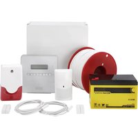
Scope of delivery
• Secvest mobile communication module
- Mobile communication antenna
• Installation instructions and user guide
Technical data
| Technical data | |
| Dimensions (L x W x H) | 63 x 40 x 12 mm |
| Weight | 18 g |
| Frequency range and Max. radio output power | Tri-band LTE: 1800 MHz (B3), 900 MHz (B8) and 800 MHz (B20); 316 mWDual band: GSM/GPRS/EDGE: 900 MHz, 2 W and 1800 MHz, 1 W |
| SIM card type | Micro SIM (3FF) 1.8 V / 3.0 V, 15 x 12 mm |
| Wireless mobile phone network | SIM card and network provider supporting 4G and 2G |
| Environmental class | II |
| Operating temperature | -10 °C to +55 °C |
| Humidity | Max. 93% (non-condensing) |
| Power supply | Via the motherboard of the alarm panel |
| Antenna cable length | Approx. 300 cm |
| Antenna connector | MMCX (on the cable) 50 Ohm |
| Antenna socket | MMCX (on the module) 50 Ohm |
| Standards for intrusion and panic button devices | EN 50131-10:2014; EN 50136-1:2012, EN 50136-2:2013. |
| ATS category | SP2, EN 50136-2 (EN: ATS Class) |
Functional principle and features
Functional principle and features
General
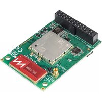
The Secvest mobile communication module (ESMO50000) is an optional accessory module for the Secvest radio alarm system. This product needs to be installed by a specialist company.

Important
At least S/W V3.00.06 or higher must be installed on the FUAA50XXX.
It enables communication via the GSM and LTE mobile phone network with stationary and mobile telephone connections. In addition, it enables SMS messages to be sent and DTMF/FSK and IP-based control centre protocols and IP-based communication (e.g. e-mails) to be transmitted.
The module is installed on the inside of the alarm panel. The motherboard includes a plug connector designed for this purpose. The antenna cable is connected directly to the module. The module can be operated using an external antenna, or an antenna integrated into the circuit board. The switching is carried out in the "Installation menu" → "System" → "Hardware" → "Mobile antenna" (internal/external)

Note
- Before you begin the installation, please check whether the selected service provider and installation location of the alarm system, as well as the potential position of the antenna, are suitable for GSM and LTE transmission.
- In principle, we recommend the use of contract cards in order to ensure a secure transmission. Prepaid cards will not work without sufficient credit.
- The external antenna must be installed outside of the alarm panel. It also helps to improve low GSM and LTE signal levels. As the module
Functional principle and features
| already has an internal antenna, the external antenna is optional but its use is recommended. | |
| Incorrect or unclean installation work may lead to erroneous interpretation of signals, the consequences of which may include false alarms. The costs incurred by potential dispatches of rescue services, such as the fire service or police, must be borne by the operator of the system. | |
 Danger Danger | The alarm panel must be completely powered off to install the module, and in order to do this the (backup) battery must be unplugged. No liability is accepted for any damage caused in the event of non-observance. Any guarantee claims will also be invalidated in the event of non-observance. |
Performance overview
Depending on function, the mobile communication module uses either the GSM system (2G) or the LTE system (4G). There is a detailed breakdown in the following table:
| Function | System |
| AES/NSL reporting (DTMF and FSK-based) | 2G |
| AES/NSL reporting (IP-based, e.g.DC-09) | 4G and 2G* |
| Emergency call (DTMF-based) | 2G |
| Voice dialler (analogue) | 2G |
| Voice dialler (VoIP/SIP) | Via Ethernet (WAN) |
| Voice dialler (VoLTE) | × |
Functional principle and features
| 2-way communication | 2G |
| Remote Control by Phone | 2G |
| SMS | 2G |
| E-mail (with photos) | 4G |
| E-mail (without photos) | 4G and 2G* |
| Web server | Via Ethernet (LAN / WAN) |
| IP camera | Via Ethernet (LAN / WAN) |
| DynDNS ABUS Server | Via Ethernet (WAN) |
| SNTP (time synchronisation) | 4G and 2G* |
| Smartphone app | Via Ethernet (WAN) |
| Push messages | 4G and 2G* |
*If the 4G system is not available due to low signal strength, the module reverts to the 2G system

Note
Voice-based communication always uses 2G.
Functional principle and features
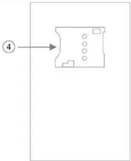
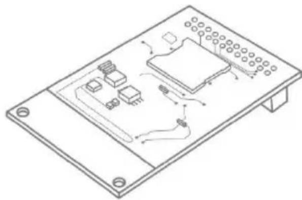
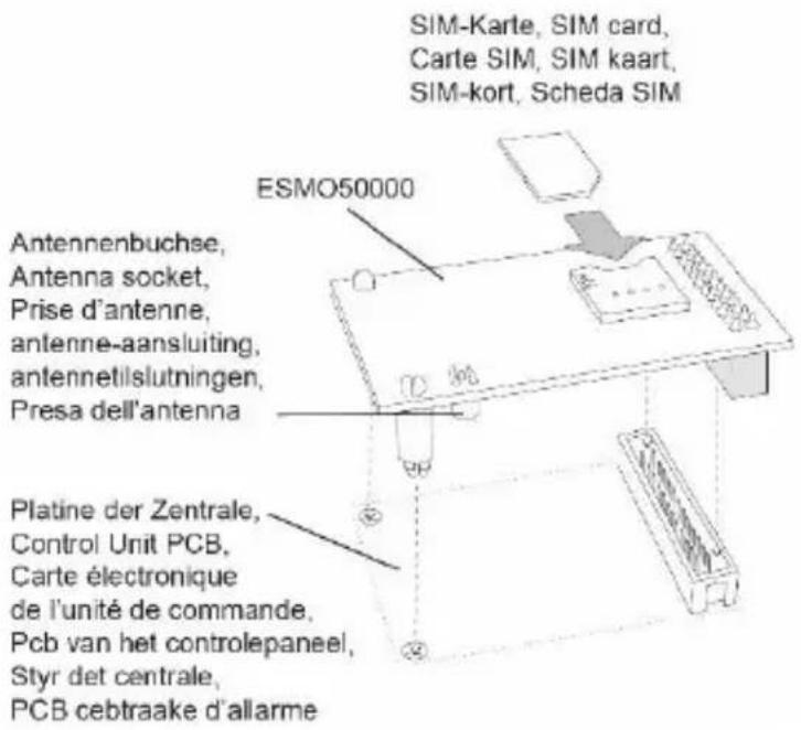
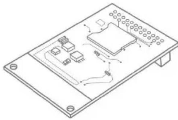
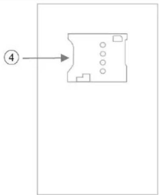
Device description
| 1 | Connection strip |
| 2 | Connection socket for the external mobile communication antenna |
| 3 | Holes for plastic holder |
| 4 | SIM card holder |
Rear
Front

flowchart
graph TD
    A["④"] --> B["Process Box"]
    style B fill:#f9f,stroke:#333,stroke-width:2px
Installation
Installation
Positioning of the antenna
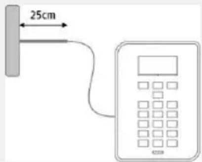
Before you begin installing the mobile communication module, please decide on a suitable position for the antenna. When doing so, pay attention to the antenna's cable length.
The following points will enhance signal strength and must be considered:

Note
• Install the antenna so it is as high as possible.
• Install the antenna so it is as far as possible from the alarm system.
- Maintain a distance of at least one metre from metallic objects (steel beams in the wall, lines, pipes, metal cabinets etc.).
- Make sure that at least 25 cm of the cable leads horizontally from the antenna. (See figure)
Signal strength pre-test
There are two ways to test the signal strength in advance:
1. By temporarily installing the mobile communication module in the alarm system
For this method, please observe the steps described for the use of the module in this user guide. Before doing this, ensure that the SIM card that is to be used has been registered. Make sure that the SIM card is not blocked with a PIN or PIN=0000.
2. By using a mobile phone
For this method, ensure that the SIM to be used for the test is from the same provider, or temporarily use the SIM card that will ultimately be used in the mobile communication module in the mobile phone. Hold the phone in the exact place in which you want to install the mobile communication antenna and check the signal strength.
Make sure that the signal strength on the mobile phone is displayed by bars, usually by 4 bars. The signal strength on the mobile communication module is displayed in numbers in the info menu of the alarm panel. The numbers range from 0 (very low) to 9 (very high). 1 bar corresponds to 2-3, 2 bars correspond to 4-5, 3 bars correspond to 6-7, and 4 bars correspond to 8-9

If you have found a position with good signal strength (at least 2 bars on the phone), ensure that the centre of the antenna is located within 2 cm of this point, because the mobile communication wavelength is very short and even small discrepancies may lead to a significant deterioration of the signal. This could significantly affect operation, in particular when the level is generally poor, and may prevent the registration of the module in the mobile communication network.
Installation
Using the mobile communication module

Note
If the alarm panel is already in operation, put the panel into installation mode. This ensures that opening the housing will now not trigger a sabotage alarm.
| 1. | Open the housing of the alarm panel. |
| 2 | Disconnect the alarm panel from the power supply. To do this, disconnect both the external power supply (unit / 230 V connection) and the backup batteries.Only for FUAA50xxx: Carefully remove the ribbon cable which connects the key panel/touch panel and the motherboard. |
| 3 | Lead the antenna cable from the outside through the cable openings in the back panel into the inside of the housing. Secure the antenna outside the housing. |
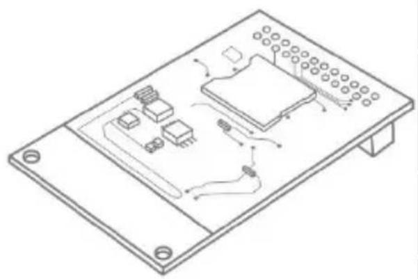
| 4 | Connect the mobile antenna to the mobile communication module (see figure). |
| 5 | Insert the SIM card into the card holder of the mobile communication module (see figure). The PIN code of the SIM card must be switched off or set to "0000". The PIN code of the SIM card must be switched off or set to "0000". |
| 6 | Equip the mobile communication module with the supplied plastic holders. Now carefully place the mobile communication module on the plug connectors of the motherboard and press down firmly. Ensure that the pins do not get bent. (See figure) |
| 7 | Only for FUAA50xxx: Now reconnect the key panel/touch panel to the motherboard.Reconnect the power to the alarm panel, and reattach the (backup) battery. Reconnect the (backup) battery and reconnect the alarm panel to the mains supply. |
Installation
8 Place the cover on the housing and tighten the locking screw(s).
9 Select the required settings on the alarm panel in the installation menu. Check that the mobile communication module is functioning correctly in the test menu of the alarm panel.
Displays and functions
Displays and functions
Installation and programming
In order to complete programming on the alarm panel, please observe the installation and user guide for the alarm panel. The options for programming of communication for the alarm system can be found in the installation menu under "Communication".

Ensure that the alarm panel does not display setting options for the mobile communication module if it is not inserted.
If the alarm panel recognises the mobile communication module, then "mobile" is displayed in the installation menu of the Secvest under the item "Info" →
"Communication".
In addition to this, you will be shown the mobile communication network name with the current signal strength, the IMEI, the telephone number of the SIM card, the IMSI and the version number of the module.
The SIM card telephone number is only displayed if your service provider has saved the telephone number on the card.

If the signal strength is too weak, then the alarm panel should be installed in a different location or the supplied antenna should be installed so that there is optimum signal strength. Please find out about your service provider's network coverage in advance, and change providers if necessary.
Testing for correct functioning using the alarm panel
Go to "Test", to the menu options NSL Reporting, Emergency Call, Voice Dialer, SMS or Email, in the installation menu in order to test the functionality of the mobile communication module. Select the appropriate communication method, such as IP mobile or mobile.
You can find details in the instructions for installers for the alarm panel in question.
Displays and functions
You can carry out a standard test call in the user menu under 'Test'.
Subsequently, you can also top-up any prepaid card that may be used with credit at this point. The keys '*' and '#' are also available for the designation of functions during the top-up process.
Unlock / register SIM card

Make sure that the PIN function is deactivated for your SIM card, or that the PIN is set to "0000". This is done during earlier configuration of the SIM in your mobile phone.
Choose the option 'Test' → 'Telephone call' in the user menu. Dial the telephone number specified by the provider and follow the service provider's instructions. Check that the mobile communication module cannot display any incoming SMS from the provider. The keys '*' and '#' can also be designated for manual activation.

'Not Reg.'
'Reg. Home'
'Searching...'
"Reg. Denied"
"Reg. Unknown"
'Reg. Roam'
The menu "Info > Communication > Mobile > Network" displays a range of information on registering the SIM card on the network. If you have any problems, check here.
Not registered; the mobile communication module is not looking for a new service provider.
Registered; home network ('Reg. Home' is replaced with the provider name as soon as this becomes available).
Not registered; the mobile communication module is looking for a provider
Registration denied
Unknown
Registered; roaming network ("Reg. Roam") is replaced with roaming provider name as soon as this becomes available.
Warranty
Information on service providers
First and foremost, follow the information from the provider on the registration of the SIM card. We recommend that the card should be registered via a mobile phone before installation, because lots of providers use SMS responses during the registration process.

Use the following table in order to record the relevant data for your mobile unication module.
IMEI no:
Serial number of the SIM card:
Mobile communication
telephone number:
Warranty

Note
- ABUS products are designed and manufactured with the greatest care and tested according to the applicable regulations.
- The warranty only covers defects caused by material or manufacturing errors at the time of sale. If there are demonstrable material or manufacturing errors, the module will be repaired or replaced at the guarantor's discretion.
- In such cases, the warranty ends when the original warranty period of two years expires. All further claims are expressly rejected.
- ABUS will not be held liable for defects and damage caused by external influences (e.g. transport, use of force, operating errors), inappropriate use, normal wear and tear, or failure to observe the instructions in this manual.
Disposal
- In the event of a warranty claim, the original receipt with the date of purchase and a short written description of the problem must be supplied with the product.
- If within the first two years following purchase you discover a defect on your mobile communication module which existed at the time of purchase, contact your dealer directly.
Disposal
Dispose of the device in accordance with EC Directive 2012/19/EU – WEEE (Waste Electrical and Electronic Equipment). If you have any questions, please contact the municipal authority responsible for disposal. You can get information on collection points for waste equipment from your local authority, from local waste disposal companies or your dealer, for example.
Declaration of conformity
ABUS Security-Center GmbH & Co. KG hereby declares that this type of radio system, ESMO50000, complies with Directive 2014/53/EU. The full EU Declaration of Conformity text can be found at: www.abus.com > Item search > ESMO50000 > Downloads
The Declaration of Conformity can also be obtained from the following address:
natural_image
Isometric line drawing of an electronic circuit board with components and wiring (no text or symbols)| DE | Installations- und Bedienungsanleitung |
| EN | Installation instructions and user guide |
| FR | Instructions d’installation et d’utilisation |
| NL | Installatie- en gebruikershandleiding |
| DK | Installations- og betjeningsvejledning |
| IT | Istruzioni per l’installazione e per l’us |
Sommaire
Introduction 37
Face avant
flowchart
graph TD
    A["④"] --> B["Process Box"]
    style A fill:#f9f,stroke:#333
    style B fill:#ccf,stroke:#333
Montage
Montage
Security Tech Germany

natural_image
Isometric line drawing of an electronic device chassis with components and wiring (no text or symbols)| NL | Installatie- en gebruikershandleiding |
| EN | Installation instructions and user guide |
| FR | Instructions d'installation et d'utilisation |
| NL | Installatie- en gebruikershandleiding |
| DK | Installations- og betjeningsvejledning |
| IT | Istruzioni per l'installazione e per l'usc |
Inhoud
Inleiding 54
Voorzijde

flowchart
graph TD
    A["④"] --> B["Process Box"]
    style B fill:#f9f,stroke:#333,stroke-width:2px
Montage
Montage
Antenne positioneren
Security Tech Germany

natural_image
Isometric line drawing of an electronic device casing with internal components and wiring (no text or symbols)| DE | Installations- und Bedienungsanleitung |
| EN | Installation instructions and user guide |
| FR | Instructions d'installation et d'utilisation |
| NL | Installatie- en gebruikershandleiding |
| DK | Installations- og betjeningsvejledning |
| IT | Istruzioni per l'installazione e per l'usc |
Indhold
Indledning 71
Forside

flowchart
graph TD
    A["④"] --> B["Process Box"]
    style B fill:#f9f,stroke:#333
Montering
Montering
Modulo mobile wireless Secvest
natural_image
Isometric line drawing of an electronic circuit board with components and wiring (no text or symbols)| DE | Installations- und Bedienungsanleitung |
| EN | Installation instructions and user guide |
| FR | Instructions d'installation et d'utilisation |
| NL | Installatie- en gebruikershandleiding |
| DK | Installations- og betjeningsvejledning |
| IT | Istruzioni per l'installazione e per l'usc |
Indice
Introduzione 88
- Antenna mobile wireless
Lato anteriore