
GCRT 1440 M - Router EINHELL - Free user manual and instructions
Find the device manual for free GCRT 1440 M EINHELL in PDF.
| Product type | Lawn aerator (electric scarifier) |
| Brand | Einhell |
| Model | GCRT 1440 M |
| Supply voltage | 220-240 V ~ 50 Hz |
| Power consumption | 1400 W |
| Working width | 40 cm |
| Hook diameter | 20 cm |
| No-load speed | 280 rpm |
| Number of blades (chopping knives) | 6 pieces |
| Sound pressure level LpA | 71.71 dB(A) (uncertainty K=3 dB) |
| Sound power level LWA | 91.71 dB(A) (uncertainty K=3 dB) |
| Vibration emission value (ah) | ≤ 2.5 m/s² (uncertainty K=1.5 m/s²) |
| Adjustable handle | Yes, upper and lower with star nuts |
| Safety switch | Double manual switch (two-handed) |
| Transport wheels | Yes, 2 wheels with hubcaps |
| Cable strain relief | Yes, with mounting clip |
| Motor thermal protection | Yes, automatic shutdown in case of overheating |
| Power cable type | H05RN-F, 3×1.5 mm², max. length 50 m |
| Storage temperature | 5 to 30 °C |
| Recommended noise level | Wear hearing protection |
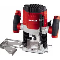
| Intended use | Aerating and scarifying lawns (flower beds) |
| Maintenance and cleaning | Clean after each use with a damp cloth; check fasteners; store dry |
| Wear parts | Chopping knives, carbon brushes, cutters |
| Warranty | 24 months (excluding professional use) |
Frequently Asked Questions - GCRT 1440 M EINHELL
User questions about GCRT 1440 M EINHELL
0 question about this device. Answer the ones you know or ask your own.
Ask a new question about this device
Download the instructions for your Router in PDF format for free! Find your manual GCRT 1440 M - EINHELL and take your electronic device back in hand. On this page are published all the documents necessary for the use of your device. GCRT 1440 M by EINHELL.
USER MANUAL GCRT 1440 M EINHELL
When using the equipment, a few safety precautions must be observed to avoid injuries and damage. Please read the complete operating instructions and safety regulations with due care. Keep this manual in a safe place, so that the information is available at all times. If you give the equipment to any other person, hand over these operating instructions and safety regulations as well. We cannot accept any liability for damage or accidents which arise due to a failure to follow these instructions and the safety instructions.
1. Safety regulations
The corresponding safety information can be found in the enclosed booklet.
Danger!
Read all safety regulations and instructions. Any errors made in following the safety regulations and instructions may result in an electric shock, fire and/or serious injury.
Keep all safety regulations and instructions in a safe place for future use.
Explanation of the symbols on the machine (Fig. 13):
- Danger! Note the instructions for use!
- Danger! If the cable is damaged or cut, pull out the power plug from the mains immediately.
- Danger! Never use the equipment in damp locations.
- Caution! Danger from catapulted parts; keep a safe distance.
- Danger! Rotating tool.
- Caution! Wear safety goggles!
- Caution! Wear ear muff s!
-
Danger! Pull the power plug before carrying out maintenance, cleaning and repair work.
-
Screw (4x)
-
Transport wheel (2x)
11.Wheel cap (2x)
2.2 Items supplied
Please check that the article is complete as specified in the scope of delivery. If parts are missing, please contact our service center or the sales outlet where you made your purchase at the latest within 5 working days after purchasing the product and upon presentation of a valid bill of purchase. Also, refer to the warranty table in the service information at the end of the operating instructions.
- Open the packaging and take out the equipment with care.
- Remove the packaging material and any packaging and/or transportation braces (if available).
- Check to see if all items are supplied.
- Inspect the equipment and accessories for transport damage.
If possible, please keep the packaging until the end of the guarantee period.
Danger!
The equipment and packaging material are not toys. Do not let children play with plastic bags, foils or small parts. There is a danger of swallowing or suffocating!
- Engine unit
Lower push bar
Top push bar
Cable strain-relief clip
Cable securing clip (2x)
Star nut (4x)
Screw (4x)
Transport wheel (2x)
Wheel cap (2x) - Original operating instructions
- Safetyinstructions
2. Layout and items supplied
2.1 Layout (Fig. 1/2)
- Top push bar
- Bottom push bar
- Motor unit
- Hoe blades
- Cable strain-relief clamp
- Two-hand safety switch
- Cable securing clips
- Star nut (4x)
GB
3. Proper use
The machine is designed for digging soil (for example garden beds). Be sure to observe the restrictions in the safety instructions.
The operating instructions as supplied by the manufacturer must be kept and referred to in order to ensure that the machine is properly used and maintained. The instructions contain valuable information on operating, maintenance and servicing conditions.
For safety reasons, the machine may not be used as a drive unit for other work tools or tool sets of any kind.
The equipment is to be used only for its prescribed purpose. Any other use is deemed to be a case of misuse. The user / operator and not the manufacturer will be liable for any damage or injuries of any kind caused as a result of this.
Please note that our equipment has not been designed for use in commercial, trade or industrial applications. Our warranty will be voided if the machine is used in commercial, trade or industrial businesses or for equivalent purposes.
4. Technical data
Voltage 220-240V 50Hz
Power input 1400 W
Working width 40 cm
Hoe diameter 20 cm
Idle speed 280 rpm
Number of blades 6 pieces
Danger!
Sound and vibration
L_pA sound pressure level 71.71 dB(A)
The impact of noise can cause damage to hearing.
Total vibration values (vector sum of three directions) determined in accordance with EN 60745.
GB
5. Before starting the equipment
Before you connect the equipment to the mains supply make sure that the data on the rating plate are identical to the mains data.
Warning!
Always pull the power plug before making adjustments to the equipment.
Assembly (Fig. 4-11)
- Remove the Philips screw (Fig. 3/Item A) with circlip and washer from both ends of the axle. Then push the transport wheel onto both ends of the axle as shown in Fig. 4 and secure with the Philips screw, circlip and washer (see Fig. 4 detail).
- Press the wheel caps (Fig. 5/Item 11) onto the transport wheels.
- Push the cable strain-relief clip (Fig. 6a/Item 5) onto the lower push bar, then push the lower push bar onto the engine unit (Fig. 6a/Item 3) as shown in Fig. 6a and secure with the screws (Fig. 6b/Item 9) and the star nuts (Fig. 6b/Item 8).
- Push the top push bar (Fig. 7a/Item 1) onto the lower push bar (Fig. 7a/Item 2) and secure with the screws (Fig. 7a/Item 9) and the star nuts (Fig. 7a/Item 8).
- Fit the two-hand safety switch on the top push bar as shown in Fig. 7b and 7c.
- Fasten the cable with the 2 cable securing clamps (Fig. 8/Item 7) to the push bars.
Power supply
The machine can be connected to any light socket-outlet (with 230 Volt alternating current). However, the socket outlet must have an earthing contact protected by a 16 A circuit breaker. Additionally, a residual current device (RCD) circuitbreaker with max. 30mA must be used! Power cable for the device
Please only use power cables that are not damaged. The total length of the power cable should not exceed 50 meters; going beyond this distance will reduce the power output of the electric motor.
The power cable must have a cross-section of 3 × 1.5 mm^2 . The insulating sheath of such machines is frequently damaged.
Some of the causes for this are:
- Cracking due to old age of the insulation
- Kinking caused by improper fastening or guidance of the power cable
Even though power cables with damaged insulation sheaths pose a lethal hazard, some people still use them. Do not make this mistake! Cables, plugs and socket couplers must meet the following requirements listed below. Power cables used to connect machines must have a rubber insulation sheath.
The power cables must, at the very minimum, be of type HO5RN-F and 3-stranded. The cable type must be printed somewhere on the power cable. Only purchase power cables that are marked! Plugs and socket couplers for the power cables must be made from rubber and splash-proof.
There is a limit to how long power cables can be. Longer power cables require larger conductor cross-sections. Power cables and connecting lines must be regularly checked for damage. Ensure that the lines are de-energized before checking them. Completely unwind the power cable. Also check power cable entry points, plugs and socket couplers for kinks.
6. Operation
6.1 Starting up
Connect the machine's power supply cable (Fig 9/Item B) to the plug (Fig. 9/Item A) and secure the power cable with the strain-relief clamp (Fig 9/Item 5).
Danger! To prevent accidental start-up of the machine, the push-bar is equipped with a two-point switch (Fig. 10/Item A) which must be pressed before the lever switch (Fig. 10/Item B) can be pressed. If the lever switch is released, the machine switches off. Repeat this process several times so that you are sure that your machine functions properly. Before you perform any repair or maintenance work on the machine, ensure that the hoe blades are not rotating and that the power supply is disconnected.
The equipment must be moved into operating position before you begin with your work. First pull the locking pin (Fig. 11/Item A) in the direction of the arrow as shown in Fig. 11 and swing up the wheel unit until the locking pin engages again in position B. Proceed in reverse order to move the equipment into transport position.
GB
Always ensure that a safe distance (provided by the long handles) is maintained between the machine and the user. Be especially careful when changing direction on slopes and inclines.
Maintain a solid footing and wear sturdy, non-slip footwear and long trousers. Always work along the incline (not up and down).
Use special caution when backing up and pulling the machine (stripping hazard).
6.2 Tips for proper working
Place the machine in front of the area you wish to hole and hold it securely on the push bar before you switch on the machine. Guide the hoe blades over the area.
To achieve cleanly hoed soil always ensure that you guide the machine in straight lines wherever possible. Insodoing, the aeration swaths should always overlap each other by a few centimeters in order to avoid bare strips.
Switch off the motor promptly when you arrive at the end of the area you wished to hoe. The motor must be switched off when you raise the machine (for example to change direction).
Keep the underside of the machine clean and remove soil deposits. Deposits make it more difficult to start the machine and decrease the working depth. Work perpendicular to the slop on inclined areas. The machine must be switched off and the mains cable disconnected before you make any checks on the hoe blades.
Warning!
The hoe blades will continue to rotate for a few seconds after the motor is switched off. Never attempt to manually stop them. In the event that the rotating hoe blade strikes an object, immediately switch off the machine and wait for the hoe blades to come to a complete stop. Then inspect the condition of the hoe blades. Replace any parts that are damaged.
Lay the power cable on the ground in front of the outlet in a fi gure 8. Work away from the outlet or cable and ensure that the power cable always trails in the hoed soil which will prevent the hoe blades from traveling over the cable.
7. Replacing the power cable
Danger!
If the power cable for this equipment is damaged, it must be replaced by the manufacturer or its after-sales service or similarly trained personnel to avoid danger.
8. Cleaning, maintenance and ordering of spare parts
Danger!
Maintenance and cleaning work on the machine as well as removal of the safety devices may only be performed when the motor is switched off and the power cable has been pulled.
8.1 Cleaning
- Keep all safety devices, air vents and the motor housing free of dirt and dust as far as possible. Wipe the equipment with a clean cloth or blow it with compressed air at low pressure.
We recommend that you clean the device immediately each time you have finished using it.
Clean the equipment regularly with a moist cloth and some soft soap. Do not use cleaning agents or solvents; these could attack the plastic parts of the equipment. Ensure that no water can seep into the device. The ingress of water into an electric tool increases the risk of an electric shock.
8.2 Replace the hoe blades
For safety reasons, we recommend having the hoe blades replaced by an authorized professional (see address on warranty certifi cate).
Wear working gloves. Use only genuine spare parts since otherwise the function and safety of the machine cannot be guaranteed.
8.3 Maintenance
Ensure that all mounting components (i.e. screws, bolts, nuts etc.) are always tightened so that the machine can be safely operated at all times. Store the device in a dry room. All the metal parts should be cleaned and then oil to ensure that they provide a long life. For best results, clean the plastic parts of the machine with a brush or rag.
Do not use any solvents to remove dirt.
For space saving storage undo the star nuts (Fig.
12/Item 8) and fold together the push bars as
GB
shown in Fig. 12. Ensure that you do not damage the cable. At the end of the season, perform a general inspection of the machine and remove any deposits which may have accumulated. At the start of each season, ensure that you check the condition of the machine. If repairs are necessary, please contact one of our customer service centers (see address on warranty certifi cate).
8.4 Ordering replacement parts:
Please quote the following data when ordering replacement parts:
Type of machine
Article number of the machine
Identification number of the machine
- Replacement part number of the part required For our latest prices and information please go to www.isc-gmbh.info
9. Disposal and recycling
The equipment is supplied in packaging to prevent it from being damaged in transit. The raw materials in this packaging can be reused or recycled. The equipment and its accessories are made of various types of material, such as metal and plastic. Never place defective equipment in your household refuse. The equipment should be taken to a suitable collection center for proper disposal. If you do not know the whereabouts of such a collection point, you should ask in your local council offices.
10. Storage
Store the equipment and accessories in a dark and dry place at above freezing temperature. The ideal storage temperature is between 5 and 30
°C. Store the electric tool in its original packaging.
GB
11. Troubleshooting guide
| Fault Possible causes Remedy | ||
| Motor does not start | - No power at the plug - Cable defective - Switch/plug block defective - Motor terminals or capacitor disconnected - excessive working depth | - Check the power cable and fuse - Check - By customer service workshop - By customer service workshop - Reduce working depth |
| Motorperformance drops | -Soiltoohard - Blades badly worn | -Correctworkingdepth -Replace hoe blades |
Notice! For protection, the motor is equipped with a thermal switch which cuts out when the motor is overloaded and switches on again automatically after a short cooling period.
GB

For EU countries only
Never place any electric power tools in your household refuse.
To comply with European Directive 2012/19/EC concerning old electric and electronic equipment and its implementation in national laws, old electric power tools have to be separated from other waste and disposed of in an environment-friendly fashion, e.g. by taking to a recycling depot.
Recycling alternative to the return request:
As an alternative to returning the equipment to the manufacturer, the owner of the electrical equipment must make sure that the equipment is properly disposed of if he no longer wants to keep the equipment. The old equipment can be returned to a suitable collection point that will dispose of the equipment in accordance with the national recycling and waste disposal regulations. This does not apply to any accessories or aids without electrical components supplied with the old equipment.
The reprinting or reproduction by any other means, in whole or in part, of documentation and papers accompanying products is permitted only with the express consent of the iSC GmbH.
Subject to technical changes
GB
Service information
We have competent service partners in all countries named on the guarantee certificate whose contact details can also be found on the guarantee certificate. These partners will help you with all service requests such as repairs, spare and wearing part orders or the purchase of consumables.
Please note that the following parts of this product are subject to normal or natural wear and that the following parts are therefore also required for use as consumables.
| Category Example | |
| Wear parts* Carbon brushes, cultivator blade | |
| Consumables* | |
| Missing parts |
- Not necessarily included in the scope of delivery!
In the effect of defects or faults, please register the problem on the internet at www.isc-gmbh.info. Please ensure that you provide a precise description of the problem and answer the following questions in all cases:
Did the equipment work at all or was it defective from the beginning?
- Did you notice anything (symptom or defect) prior to the failure?
What malfunction does the equipment have in your opinion (main symptom)?
Describe this malfunction.
GB
Warranty certificate
Dear Customer,
All of our products undergo strict quality checks to ensure that they reach you in perfect condition. In the unlikely event that your device develops a fault, please contact our service department at the address shown on this guarantee card. You can also contact us by telephone using the service number shown. Please note the following terms under which guarantee claims can be made:
- These guarantee conditions regulate additional guarantee services. Your statutory guarantee claims are not affected by this guarantee. Our guarantee is free of charge to you.
- Our guarantee only covers defects suffered by the device which have been verifiably caused by a material or manufacturing fault and is limited to the rectification of such defects or the replacement of the device at our discretion.
Please note that our devices are not designed for use in commercial, trade or professional applications. A guarantee contract will not be created if the device has been used by commercial, trade or industrial business or has been exposed to similar stresses during the guarantee period.
-
The following are not covered by our guarantee:
-
Damage to the device caused by a failure to follow the assembly instructions or due to incorrect installation, a failure to follow the operating instructions (for example connecting it to an incorrect mains voltage or current type) or a failure to follow the maintenance and safety instructions or by exposing the device to abnormal environmental conditions or by lack of care and maintenance.
-
Damage to the device caused by abuse or incorrect use (for example overloading the device or the use or unapproved tools or accessories), ingress of foreign bodies into the device (such as sand, stones or dust, transport damage), the use of force or damage caused by external forces (for example by dropping it).
-
Damage to the device or parts of the device caused by normal or natural wear or tear or by normal use of the device.
-
The guarantee is valid for a period of 24 months starting from the purchase date of the device. Guarantee claims should be submitted before the end of the guarantee period within two weeks of the defect being noticed. No guarantee claims will be accepted after the end of the guarantee period. The original guarantee period remains applicable to the device even if repairs are carried out or parts are replaced. In such cases, the work performed or parts fitted will not result in an extension of the guarantee period, and no new guarantee will become active for the work performed or parts fitted. This also applies if an on-site service is used.
- Please report the defective device on the following internet address to register your guarantee claim: www.isc-gmbh.info. If the defect is covered by our guarantee, then the item in question will either be repaired immediately and returned to you or we will send you a new replacement device.
Of course, we are also happy offer a chargeable repair service for any defects which are not covered by the scope of this guarantee or for units which are no longer covered. To take advantage of this service, please send the device to our service address.
Also refer to the restrictions of this warranty concerning wear parts, consumables and missing parts as set out in the service information in these operating instructions.
F
Danger!
Chere cliente, cher client,
Evnpwon yia to epbic
GB explains the following conformity according to EU directives and norms for the following product
□90/396/EC_2009/142/EC
89/686/EC_96/58/EC
2011/65/EC
2006/42/EC
Annex IV
Notified Body: Notified Body
Reg.No
2000/14/EC_2005/88/EC
Annex V
Annex VI
Noise: measured L_WA = 91,71 dB (A); guaranteed L_WA = 93 dB (A)
P=1,4 KW; L/0 = 40 cm
Notified Body: Société Nationale Certification et d'Homologation (SNCH) S.A.R.L. (0499)
2004/26/EC
Emission No.:
Standard references: EN 60335-1; EN 709; EN 62233; EN 55014-1; EN 55014-2; EN 61000-3-2; EN 61000-3-3
Subject to change without notice
Archive-File/Record: NAPR006370
Documents registrar: Alexander Scheifl
Wiesenweg 22, D-94405 Landau/Isar


-90
-91-
EH 11/2014 (01)


- Safety regulations
- Danger!
- Items supplied
- Layout and items supplied
- Layout (Fig. 1/2)
- GB
- Proper use
- Technical data
- Sound and vibration
- Before starting the equipment
- Warning!
- Assembly (Fig. 4-11)
- Power supply
- Some of the causes for this are:
- Operation
- Starting up
- Tips for proper working
- Replacing the power cable
- Cleaning, maintenance and ordering of spare parts
- Cleaning
- Replace the hoe blades
- Maintenance
- Ordering replacement parts:
- Disposal and recycling
- Storage
- Troubleshooting guide
- Service information
- Warranty certificate
- Dear Customer,
- F
- Evnpwon yia to epbic
Brand : EINHELL
Model : GCRT 1440 M
Category : Router