
FUMO50040 - Alarm system ABUS - Free user manual and instructions
Find the device manual for free FUMO50040 ABUS in PDF.
| Product type | Outdoor IP surveillance camera |
| Compatible models | IPCB42501 (wired), IPCB42551 (WiFi) |
| Maximum resolution | 1920 x 1080 pixels (Full HD) |
| Video compression | H.264 |
| Night vision | Yes, with integrated IR illumination (range varies depending on environment) |
| WDR (Wide Dynamic Range) | Yes (model IPCB42551) |
| Two-way audio | Yes (model IPCB42551, built-in microphone and speaker) |
| Network connectivity | Ethernet 10/100, WiFi 802.11 b/g/n (IPCB42551) |
| Power supply | PoE (Power over Ethernet) or 12 V DC power adapter |
| Local storage | microSD card (up to 128 GB recommended) |
| Motion detection | Yes, with configurable zones |
| Alarm inputs/outputs | 1 input, 1 output (model IPCB42551) |
| Supported protocols | TCP/IP, HTTP, RTSP, FTP, SMTP, DDNS, UPnP, etc. |
| Operating temperature | -20 °C to +50 °C (estimated) |
| Protection rating | IP67 (outdoor, estimated) |
| Maintenance and cleaning | Clean with a soft, dry cloth. Do not use chemical products. |
| Security | Password authentication, IP filtering, HTTPS encryption, SSH |
| Spare parts and repairability | No user-serviceable parts. Contact ABUS support. |
| General information | Compliant with EMC Directive 2014/30/EU, RoHS 2011/65/EU, RED 2014/53/EU (IPCB42551) |
Frequently Asked Questions - FUMO50040 ABUS
User questions about FUMO50040 ABUS
0 question about this device. Answer the ones you know or ask your own.
Ask a new question about this device
Download the instructions for your Alarm system in PDF format for free! Find your manual FUMO50040 - ABUS and take your electronic device back in hand. On this page are published all the documents necessary for the use of your device. FUMO50040 by ABUS.
USER MANUAL FUMO50040 ABUS
IPCB42501 / IPCB42551
Bedienungsanleitung Software
UK User manual software
FR Manuel utiliseur logiciel
Gebruikershandleiding software
Brugerhandbog software
| D | These Bedienungsanleitung enthalt wichtige Hinweise zur Inbetriebnahme und Handhabung. Achten Sie hierauf, auch wenn Sie thesees Produkt an Dritte weitergeben. Hebben Sie deshalb diese Bedienungsanleitung zum Nachlesen auf! Eine Auflistung der Inhalte finden Sie im Inhaltsverzeichnis mit Angabe der entspruchenden Seitenzahlen auf Seite 6. | DK | Denne manual hører sammen med dette produit. Den indeholder vigtig information som skal bruges under opsæthing og afterfølgende ved service. Dette skal huskes øsså närprodukter gives videre til,anden part. Laes derfor dette manual grundigt igennem øsså for fremtiden. Indholdet kan ses med sideanusinger kan findes i indekset på side 215. |
| GB | These user manual contains important information for installation and operation. This should be also noted when this product is passed on to a third party.Therefore look after these operating instructions for future reference! A list of contents with the corresponding page number can be found in the index on page 63. | ||
| F | Ce mode d'emploi apparent à de produit. Il contient des recommendations en ce qui concerne sa mise en service et sa manutention. Veuillez en tenir compte et ceci également lorsque vous remette le produit à des tiers. Conserve ce mode d'emploi afin de pouvoir vous documenter en temps utile! Vous trouverez le récapitulatif des indications du contentu à la table des matières avec mention de la page correspondante à la page 114. | ||
| NL | Deze gebruiksaanwijzing hoorbij dit product. Er staan belagrijke aanwijzingen in betreffende de ingebruikname en gebruik, ook als u dit product doorgeeft aan derden. Bewaar deze hendleiding zorgvuldig, zodat u deze later nog eens kunt nalezen! U vindt een opsomming van de inhoud in de inhoudsopgave met aanduiding van de paginanummers op pagina 165. |
IPCB42501 / IPCB42551
| True | WDR | WDR | IR | |
| IPCB42501 | - √ √ | - | ||
| IPCB42551 | - | √ | √ | √ |

DSCP - Differentiated Service CodePoint
IPCB42501 / IPCB42551
User manual Software
Version 02/2017
IPCB42501
IPCB42551
Dear Customer,
Thank you for purchasing this product.
IPCB42501
This device complies with the requirements of the following EU directives: the EMC Directive 2014/30/EU and the RoHS Directive 2011/65/EU. The full EU Declaration of Conformity text can be found at: www.abus.com/product/IPCB42501
IPCB42551
ABUS Security-Center hereby declares that this type of wireless system IPCB42551, complies with RED Directive 2014/53/EU. Additionally, this device complies with the requirements of the following EU directives: the EMC Directive 2014/30/EU and the RoHS Directive 2011/65/EU. The full EU Declaration of Conformity text can be found at: www.abus.com/product/IPCB42551
To ensure this condition is maintained and that safe operation is guaranteed, it is your obligation to observe this user manual.
Please read the entire user manual carefully before putting the product into operation, and pay attention to all operating instructions and safety information.
All company names and product descriptions are trademarks of the corresponding owner. All rights reserved.
If you have any questions, please contact your specialist installation contractor or specialist dealer.

Disclaimer
This user manual has been produced with the greatest of care. Should you discover any missing information or inaccuracies, please let us know about them.
ABUS Security-Center GmbH & Co. KG does not accept any liability for technical and typographical errors, and reserves the right to make changes to the product and user manuals at any time and without prior warning.
ABUS Security-Center GmbH is not liable or responsible for any direct or indirect damage resulting from the installation, performance and use of this product. No guarantee is made for the contents of this document.
Important safety information
All guarantee claims are invalid in the event of damage caused by non-compliance with this user manual. We cannot be held liable for resulting damage.

We cannot be held liable for material or personal damage caused by improper operation or non-compliance with the safety information. All guarantee claims are void in such cases.
Dear Customer,
The following safety information and hazard notes are not only intended to protect your health but also to protect the device from damage. Please read the following points carefully:
- There are no components inside the product that require maintenance by the operator. Opening or dismantling the product invalidates the CE certification and guarantee claims/warranty.
- The product may be damaged if it is dropped, even from a low height.
Avoid the following adverse conditions during operation:
- Moisture or excess humidity
- Extreme heat or cold
- Direct sunlight
- Dust or flammable gases, vapours or solvents
Strong vibrations - Strong magnetic fields (e.g. next to machines or loudspeakers)
- The camera must not be installed on unstable surfaces.
General safety information:
- Do not leave packaging material lying around. Plastic bags, sheeting, polystyrene packaging, etc. can pose a danger to children if played with.
- The video surveillance camera contains small parts which could be swallowed and must be kept out of the reach of children for safety reasons.
- Do not insert any objects into the device through the openings.
- Only use replacement devices and accessories that are approved by the manufacturer. Do not connect any non-compatible products.
- Please pay attention to the safety information and user manuals for the other connected devices.
- Check the device for damage before putting it into operation. Do not put the device into operation if you identify any damage.
- Adhere to the normal voltage limits specified in the technical data. Higher voltages could destroy the device and pose a health risk (electric shock).

When installing the device in an existing video surveillance system, ensure that all devices have been disconnected from the mains power circuit and low-voltage circuit.

If in doubt, have a specialist technician carry out assembly, installation and connection of the device. Improper or unprofessional work on the power supply system or domestic installation puts both you and other persons at risk.
Connect the installations so that the mains power circuit and low-voltage circuit always run separately
from each other. They should not be connected at any point or become connected as a
result of a malfunction.
Contents
- INTENDED USE 65
- EXPLANATION OF SYMBOLS 65
- FEATURES AND FUNCTIONS 66
- INITIAL START-UP 67
4.1 USING THE ABUS IP INSTALLER FOR CAMERA SEARCH 67
4.2 ACCESSING THE NETWORK CAMERA USING A WEB BROWSER 68
4.3. GENERAL INSTRUCTIONS FOR USING THE SETTINGS PAGES 68
4.4 INSTALLING A VIDEO PLGIN 68
4.5 HOMEPAGE (LOGIN PAGE) 70
4.6 USER ACCOUNTS AND PASSWORDS 71
4.6.1 REQUEST TO CHANGE THE DEFAULT PASSWORD 72
4.7 LINKING UP THE CAMERA WITH ABUS VMS/ABUS VMS EXPRESS 73
4.8 LINKING UP THE CAMERA WITH ABUS NVR/ABUS HYBRID DVR 73
4.9 LINKING UP THE CAMERA TO IPCAM 73
- USER MENU "USER" 74
- VIEW AND CONFIGURATION MENU USER "MASTER" 76
6.1 ADD/CHANGE/DELETE USERS 78
6.2 DEACTIVATE/ACTIVATE INSTALLER ACCESS 79
6.3 LOCAL CONFIGURATION 80
6.4 DISPLAYING/DOWNLOADING VIDEO FROM THE INTERNAL MEMORY 81
- VIEW AND CONFIGURATION MENUS USER "INSTALLER" 83
7.1 LIVE VIEW 83
7.2 HELP PAGE 83
7.3 INFO PAGE 83
7.4 SETUP WIZARD 85
7.5 ADVANCED CAMERA SETTINGS 86
7.5.1VIDEO 86
7.5.1.1 IMAGE 86
7.5.1.2PRIVACYMASKING 87
7.5.1.3VIDEO STREAM 88
7.5.2 NETWORK 89
7.5.2.1 IPv4/IPV6 SETTINGS 89
7.5.2.2 PORTS 90
7.5.2.3 DDNS 91
7.5.2.4 PPPoE 91
7.5.2.5SNMP 92
7.5.2.6 QoS 92
7.5.2.7 FTP 93
7.5.2.8 Wi-Fi (ONLY IPCB42551) 94
7.5.2.9 UPNP 95
7.5.2.10 SMTP/Email 95
7.5.2.11 NAT 96
7.5.2.12 HTTPS 96
7.5.3 SECURITY 97
7.5.3.1 IP ADDRESS FILTER 97
7.5.3.2 AUTHENTICATION 97
7.5.3.3 SECURITY SERVICE SETTINGS 97
7.5.4 OSD 98
7.5.5 DATE & TIME 99
7.5.6 SYSTEM 100
7.5.6.1 GENERAL 100
7.5.6.2FIRMWARE/RESET 101
7.5.6.3 Log FILE 101
7.5.7 EVENTS 102
7.5.7.1 MOTION DETECTION 102
7.5.7.2 COVER DETECTION 103
7.5.7.3 ALARM INPUT (ONLY IPCB42551) 103
7.5.7.4 ALARM OUTPUT (ONLY IPCB42551) 103
7.5.8 ALARM MANAGER 104
7.5.9 RECORDING 104
7.5.9.1 RECORDING SCHEDULE 105
7.5.9.2 STORAGE MANAGEMENT 105
7.5.9.3 NAS 105
7.5.9.4SNAPSHOT 106
7.5.10 AUDIO (ONLY IPCB42551) 107
7.5.11 INSTALLER 108
7.5.12 SERVICE 108
7.5.13 LOCAL CONFIGURATION 109
8. MAINTENANCE AND CLEANING 110
8.1 FUNCTION TEST 110
8.2 CLEANING 110
9. DISPOSAL 110
1. Intended use
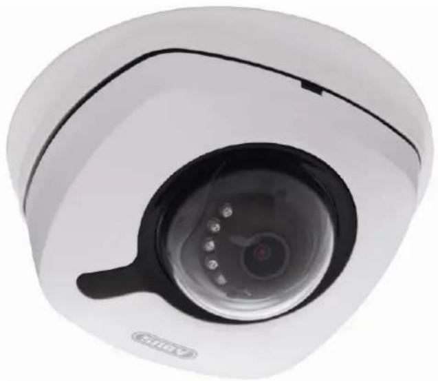
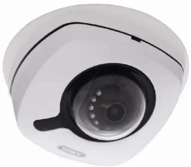
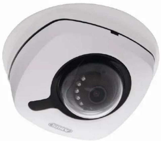
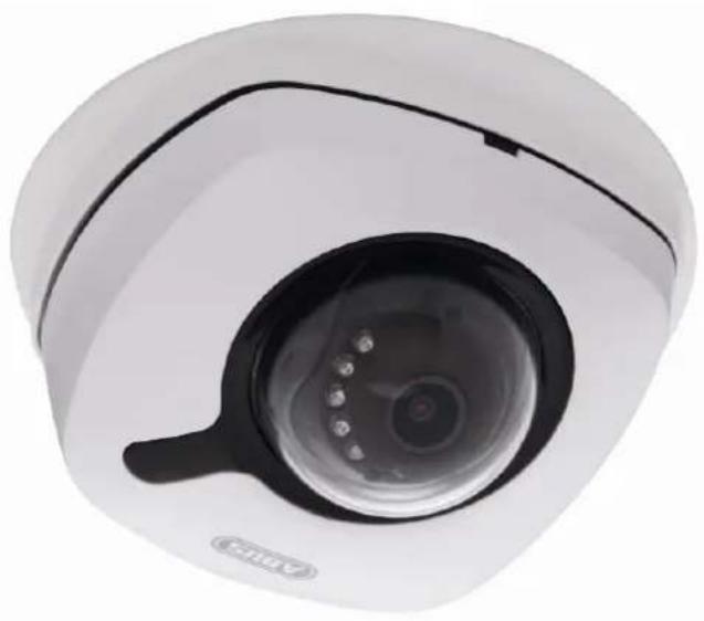
This camera is used for indoor and outdoor video surveillance (depending on the model) in conjunction with a recording device or appropriate display unit (e.g. PC).

Use of this product for any other purpose than that described may lead to damage to the product and other hazards. All other uses are not as intended and will result in the invalidation of the product guarantee and warranty. No liability can be accepted as a result. This also applies to any alterations or modifications made to the product.
Read the user guide carefully and in full before putting the product into operation. The user guide contains important information on installation and operation.
2. Explanation of symbols
The triangular high voltage symbol is used to warn of the risk of injury or health hazards (e.g. caused by electric shock).

The triangular warning symbol indicates important notes in this user manual which must be observed.

This symbol indicates special tips and notes on the operation of the device.

This user manual describes the software functions in the camera browser interface. For information about how to install the hardware for the respective camera, please read the quick start manual or the hardware installation manual, if you have it.
You can download a PDF version of the user manuals in your language at wwwabus.com via the product search.
3. Features and functions
| True WDR WDR | IR, infrared WiFi | |||
| IPCB42501 | - | √ √ | - | |
| IPCB42551 | - | √ | √ | √ |
|  | The effective IR range will depend on the installation location. If there are surfaces that absorb light or no objects that reflect IR light in the field of view, the IR range will be reduced and/or the video image will be too dark. Reflective objects in the immediate vicinity of the camera (e.g. roof gutter or wall) may also result in the reflection of IR light, which can disturb the image. |
4. Initial start-up
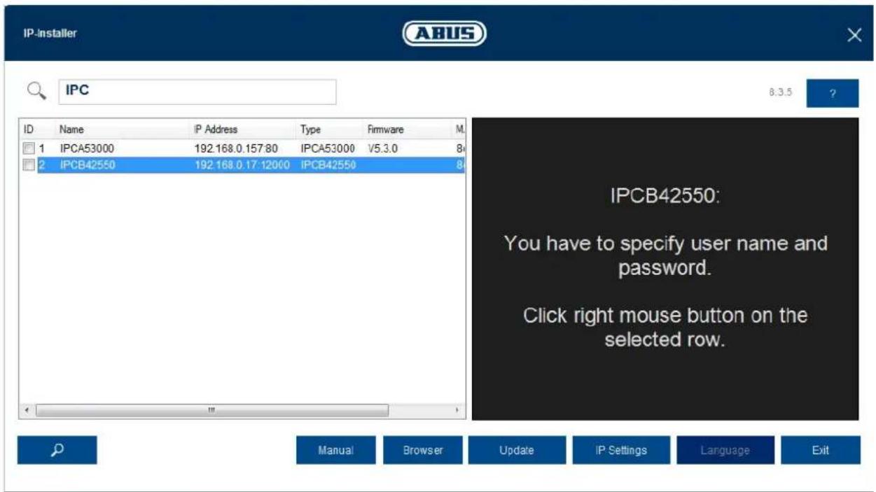
4.1 Using the ABUS IP Installer for camera search
Install and start up the ABUS IP Installer using the enclosed software CD (or alternatively using the ABUS website www.abus.com, available for each respective product).
The IP camera should now appear in the selection list without the relevant IP address for the target network, where appropriate. The IP settings for the camera can be changed using the IP installer.
The language preference for the camera can also be changed using the ABUS IP installer. This will change the language preference for the master and installer users at the same time (for an explanation of master/installer, see chapter "User accounts and passwords"). Individual language preferences can be amended in the settings menus for master and installer.

Please be aware, that the language preference for the camera homepage is set automatically depending on the operating system language preference. If this language is not available in the camera, the homepage will be shown in English.
Using the "Browser" button, a previously selected camera can be opened directly in the internet browser (the default browser for Windows will be used).
4.2 Accessing the network camera using a web browser
Enter the camera IP address into the address bar in the browser (if a different HTTP Port is used in Internet Explorer you must also enter "http://" before the IP address.)

4.3. General instructions for using the settings pages
| Functional element Description | |
| Einstellungen sichern! | Save settings that have been made on the page. Please note that the new settings will only apply after the save button has been pressed. |
| DHCP | Function activated |
| DHCP | Function deactivated |
| ABUS Server | List selection |
| 192.168.0.127 | Input field |
| 3 min. max. | Slide control |
4.4 Installing a video plugin
Internet Explorer
A plugin called ActiveX is used for displaying videos in Internet Explorer. This plugin must be installed in the browser. You will be asked to confirm the installation directly after entering your username and password (default: master/master).

If the ActiveX Plugin installation is blocked by Internet Explorer, you will need to reduce your security settings to install/initialise ActiveX.
Mozilla Firefox
A plugin is used to display videos in Mozilla Firefox. You will be asked to confirm the installation directly after entering your username and password (default: master/master or installer/installer).
Google Chrome

Note relating to Google Chrome (older versions up to Version 42): the video plugin is only supported by the Windows version of the Google Chrome browser.
In Google Chrome (up to Google Chrome Version 42), you must also make sure that the NAPI interface is activated
The most recent version of Google Chrome no longer supports video plugins. This means that it is not possible to display video.
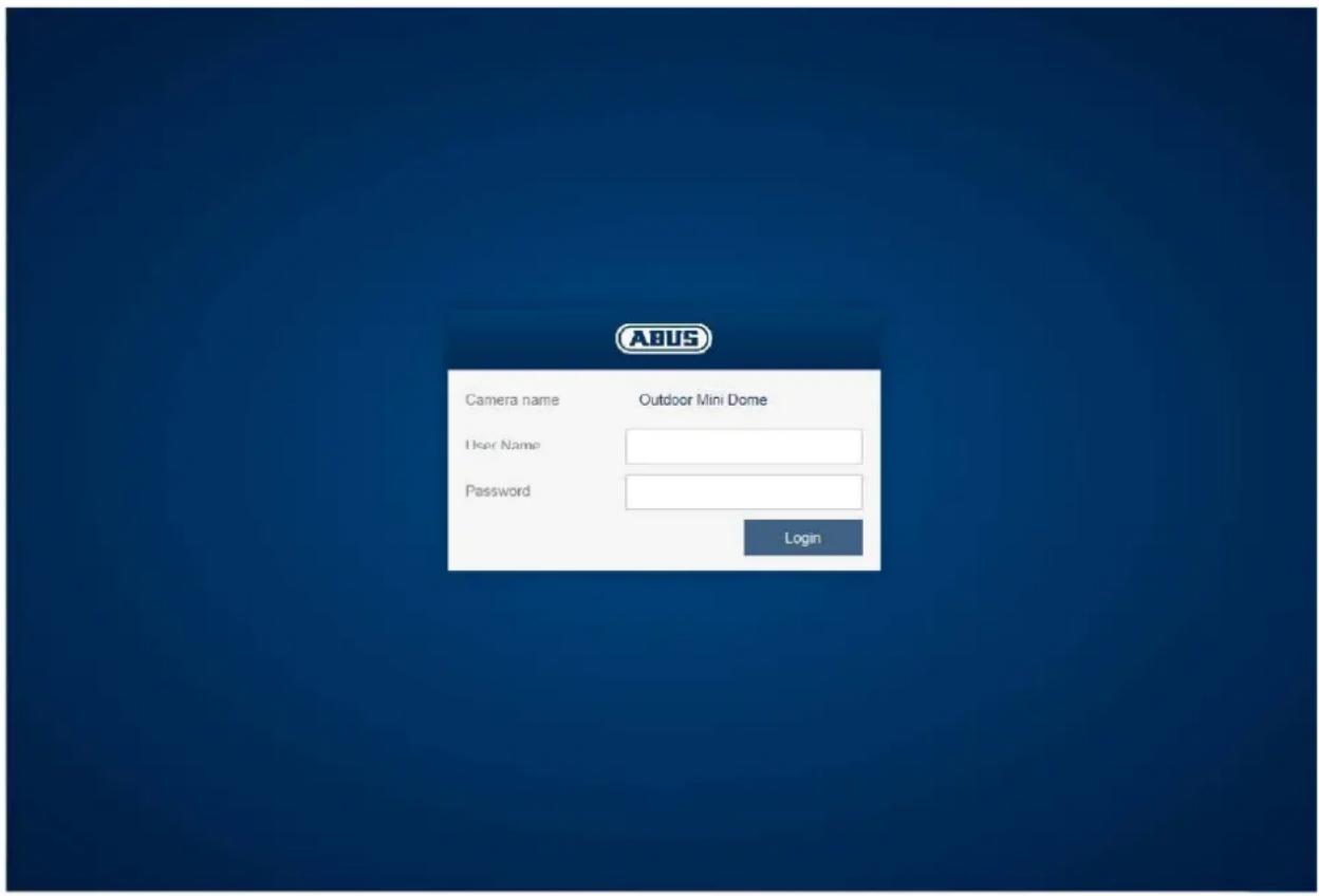
4.5 Homepage (login page)
After entering the IP address in the browser's address bar and opening up the page, the home page will appear in the language set in the Internet Explorer options (Windows setting).
Each respective user account (installer, master or user) can set their language individually. For example, the settings pages can be set to English for the "installer" account and German for the "master" account.
The following languages are supported: German, English, French, Dutch, Danish. If a language is not supported, the website will be displayed in English.
4.6 User accounts and passwords
Overview of the types of user with the username descriptions, the default passwords and corresponding privileges.
| User types | Username | Default password | Privileges |
| INSTALLER(for access via web browser, mobile app or recording device) | installer | installer | ● Video display on web browser● Instant image● Local video recording on PC● Control microphone/Speaker (optional)● Full screen mode in browser● Zoom/Focus setting (if available)● System overview● Image settings● Video streaming quality settings● Day/night switching● Privacy masking● IP address settings● Network protocol settings● Setting for connection ports● DDNS settings● HTTPS settings● SMTP settings● Displayed text● Date/Time● Export/Import/Restore● Firmware update/Restart● Log file● Motion detection settings● Alarm management (email/switch output)● Audio parameter |
| master | master | master | ● Video display on web browser● Instant image● Local video recording on PC● Control microphone/Speaker (optional)● Full screen mode in browser● Zoom/Focus setting (if available)● Add, change or delete users● Block and unblock "installer" access●Playback of recordings from the internal memory |
| user | <assigned master> | <assigned and modified by master> | ● Video display on web browser● Instant image● Local video recording on PC● Control microphone/Speaker (optional)● Full screen mode in browser |
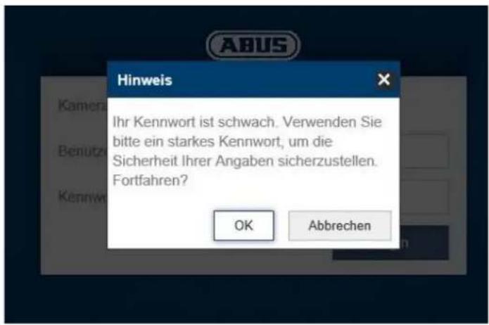
4.6.1 Request to change the default password
For security reasons, it is recommended to use a secure password with the appropriate use of lowercase letters, capital letters, numbers and special characters.
In case standard passwords such as e.g. "installer" is still used, a prompt for changing the password appears with every login to the camera web site.
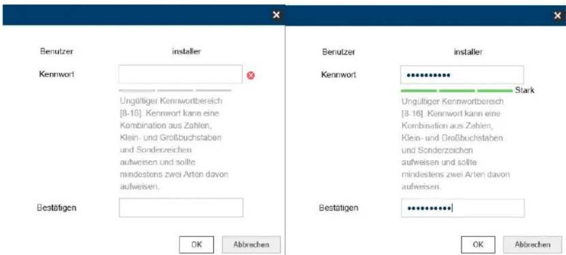
A secure password must meet at least the following requirements:
-8-16 characters
- Valid characters: numbers, lowercase letters, uppercase letters, special characters (! % & / () = ? + -)
- 2 different types of characters must be used
4.7 Linking up the camera with ABUS VMS/ABUS VMS Express
The following information is required to link up the camera with ABUS VMS/ABUS VMS Express:
- IP address/domain name
- http port (default 80)
- rtsp port (default 554, can be changed, is detected automatically)
- User name:installer
- Password: installer (can be changed via the installer settings)
4.8 Linking up the camera with ABUS NVR/ABUS Hybrid DVR
The following information is required to link up the camera with ABUS NVR/ABUS Hybrid DVR:
- IP address/domain name
- http port (default 80)
- rtsp port (default 554, may not be changed)
- User name:installer
- Password: installer (can be changed via the installer settings)
4.9 Linking up the camera to IPCam
The following information is required to link up the camera with IPCam:
- IP address/domain name
- http port (default 80)
-
rtsp port (default 554)
-
User name:installer
-
Password: installer (can be changed via the installer settings)
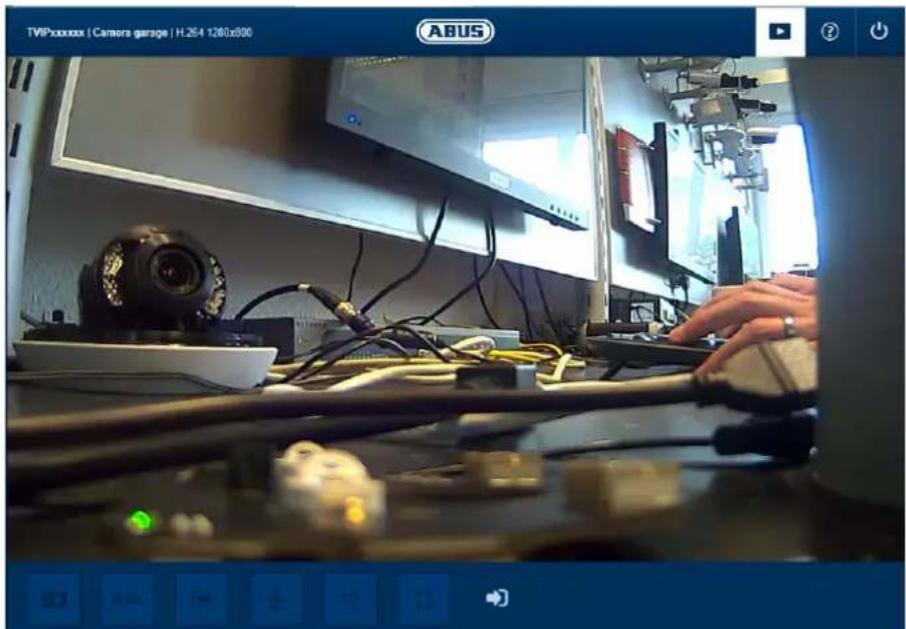
5. User menu "user"
| Button/display on screen Function | ||
| TVIPxxxxxx | Camera garage | H.264 1280x800 | Information bar | |
| Live display | ||
| Help page | ||
| Log out as user | ||
| Button/display on screen | Function |
| Instant image function | |
| This function saves an instant image from the current video stream in JPEG format. The picture is stored in the following folder: (Save location, see local configuration) |
| Video function This function saves a video from the current video stream in AVI format. The video is stored in the following folder: (Save location, see local configuration) | ||
| Activate switching output This button can be used to manually activate or deactivate the switching output (e.g. door opener function). | ||
| Muting the microphone (if available) This button can be used to deactivate the microphone in the camera or the microphone in the optional audio input. | ||
| Muting the speaker (if available) This button can be used to deactivate the speaker in the optional audio output. | ||
| Manual activation / deactivation of the switching output (if available) | ||
| Full screen mode Switching the video picture on the monitor to full screen mode (you can also do this by double clicking within the video frame). You can exit full screen mode by double clicking within the video frame again or pressing the ESC button. | ||
| Status of the switching input (if present, switching input 1) |
6. View and configuration menu user "master"
| Button/display on screen | Function | |
| Instant image functionThis function saves an instant image from the current video stream in JPEG format (see Local Configuration for save location). | ||
| Video functionThis function saves a video from the current video stream in AVI format (see Local Configuration for save location). | ||
| Muting the microphone (if available)This button can be used to deactivate the microphone in the camera or the microphone in the optional audio input. | ||
| Muting the speaker (if available)This button can be used to deactivate the speaker in the optional audio output. | ||
| Manual activation / deactivation of the switching output (if available) | ||
| Full screen mode Switching the video picture on the monitor to full screen mode (you can also do this by double clicking within the video frame). You can exit full screen mode by double clicking within the video frame again or pressing the ESC button. | |
| Status of the switching input (if present, switching input 1) | |
| Live view page for "master" user | |
| ? | Information page with explanations of what the buttons do. |
| Settings page for "master" user. | |
| Log out as user. Afterwards the login page is displayed again. |
6.1 Add/change/delete users
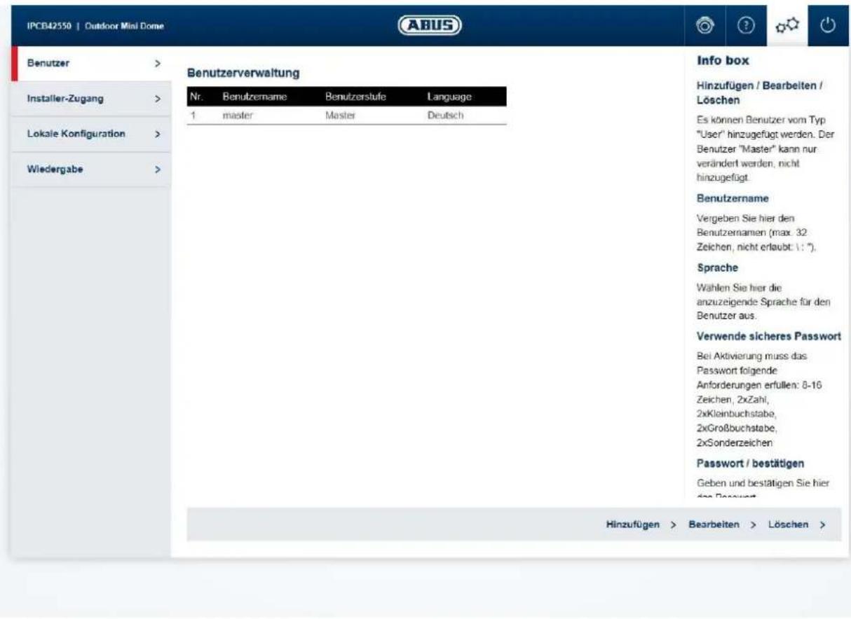
Add/edit/delete: Users with the type "User" can be added. The "Master"
user can only be modified. It cannot be added.
User name: Enter the user names here (max. 32 characters, not
allowed: : ).
Language: Select the language to be displayed for the user here.
Use a secure password:
A secure password must meet at least the following requirements:
-8-16 characters
- Valid characters: numbers, lowercase letters, uppercase letters, special characters (!$% & / (
$$ = ? + -) $$
- 2 different types of characters must be used
Password/confirm: Enter and confirm the password here.
6.2 Deactivate/activate installer access
Block user "Installer": The "Master" user can block installer access (= "Installer" user) when the installation has finished. Access can be activated again, if required.

If the "Master" or "Installer" user has forgotten their login information, you must load the factory settings for the camera via the "RESET" button. This will restore all usernames and passwords to factory settings.
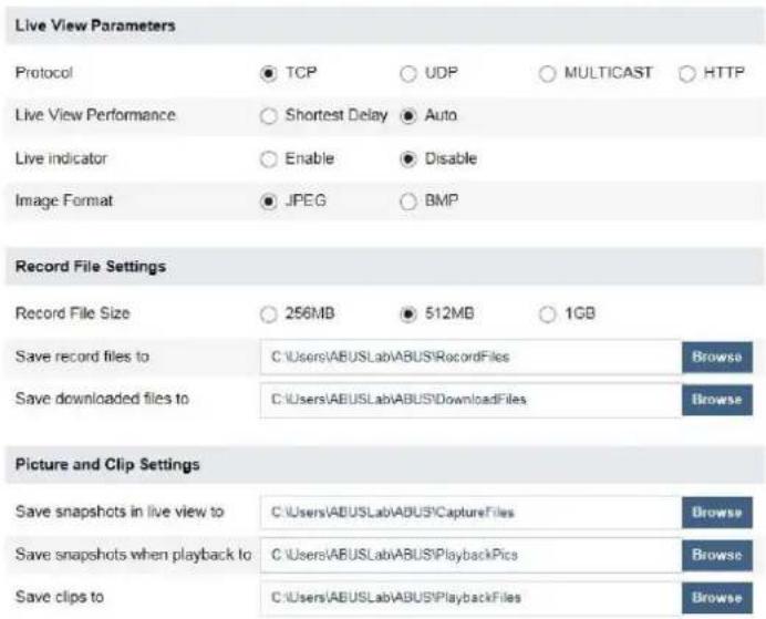
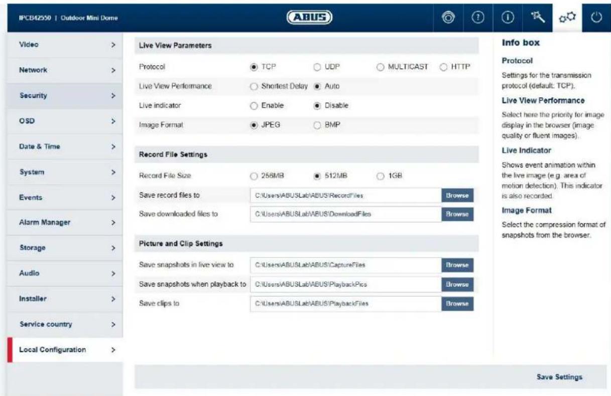
6.3 Local configuration
Info box
Protocol
Settings for the transmission protocol (default: TCP)
Live View Performance
Select here the priority for image display in the browser (image quality or fluent images).
Live Indicator
Shows event animation within the live image (e.g. area of motion detection). This indicator is also recorded.
Image Format
Select the compression format of snapshots from the browser
Protocol: Setting the transmission protocol (default: TCP)
Live view performance: Select the priority for display in the browser here (priority on image stream or image quality).
Live indicator: Display of all event animations in the live image (e.g. frame for motion detection). These animations are also recorded to the recording device.
Image format: Select the encoding format for saving single frames using the browser live interface.
Record file size: Select the size of video sequences for saving videos using the browser live interface.
Save record files to: Select the path for video recording.
Save downloaded files to: Select the path for video files downloaded from the SD card.
Save live snapshots to: Select the encoding format for saving images using the browser live interface.
Snapshots during playback: Select the path for saving images during playback.
Save clips to: Select the path for saving video clips during playback.
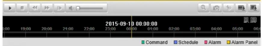
6.4 Displaying/downloading video from the internal memory

| Sun | Mon | Tue | Wed | Thu | Fri | Sat |
| 30 | 31 | 1 | 2 | 3 | 4 | 5 |
| 6 | 7 | 8 | 9 | 10 | 11 | 12 |
| 13 | 14 | 15 | 16 | 17 | 18 | 19 |
| 20 | 21 | 22 | 23 | 24 | 25 | 26 |
| 27 | 28 | 29 | 30 | 1 | 2 | 3 |
| 4 | 5 | 6 | 7 | 8 | 9 | 10 |
Q Search

| Symbol | Explanation | ||||||
| Sun | Mon | Tue | Wed | Thu | Fri | Sat | Selection of the date when searching for a recording. If data are found on the SD card, they are displayed in the playback bar by record type. First select a date and then click "SEARCH". |
| 30 | 31 | 1 | 2 | 3 | 4 | 5 | |
| 6 | 7 | 8 | 9 | 10 | 11 | 12 | |
| 13 | 14 | 15 | 16 | 17 | 18 | 19 | |
| 20 | 21 | 22 | 23 | 24 | 25 | 26 | |
| 27 | 28 | 29 | 30 | 1 | 2 | 3 | |
| 4 | 5 | 6 | 7 | 8 | 9 | 10 | |
| Search | |||||||
| Stop playback | |||||||
| Slow playback (forwards) | |||||||
| Fast playback (forwards) | |||||||
| Frame forwards | |||||||
| Playback volume (if recording contains audio data) | ||
| Enable digital zoom. Then hold down the left mouse button to draw a rectangle in the video area. The digital zoom is applied to this area. Pressing this button a second time closes the digital zoom mode. | ||
| Save single frame (save location, see local configuration) | ||
| Start/stop the video cutting function. The cut video is saved after you press stop (save location, see local configuration). | ||
| Opens a dialogue for downloading recorded video files from the SD card. | ||
| Opens a dialogue for downloading recorded image files from the SD card. | ||
| Playback bar with time and date display (display depends on temporal zoom factor). The recorded data are displayed colour-coded by record type in the playback bar. | ||
| Setting the temporal zoom factor |
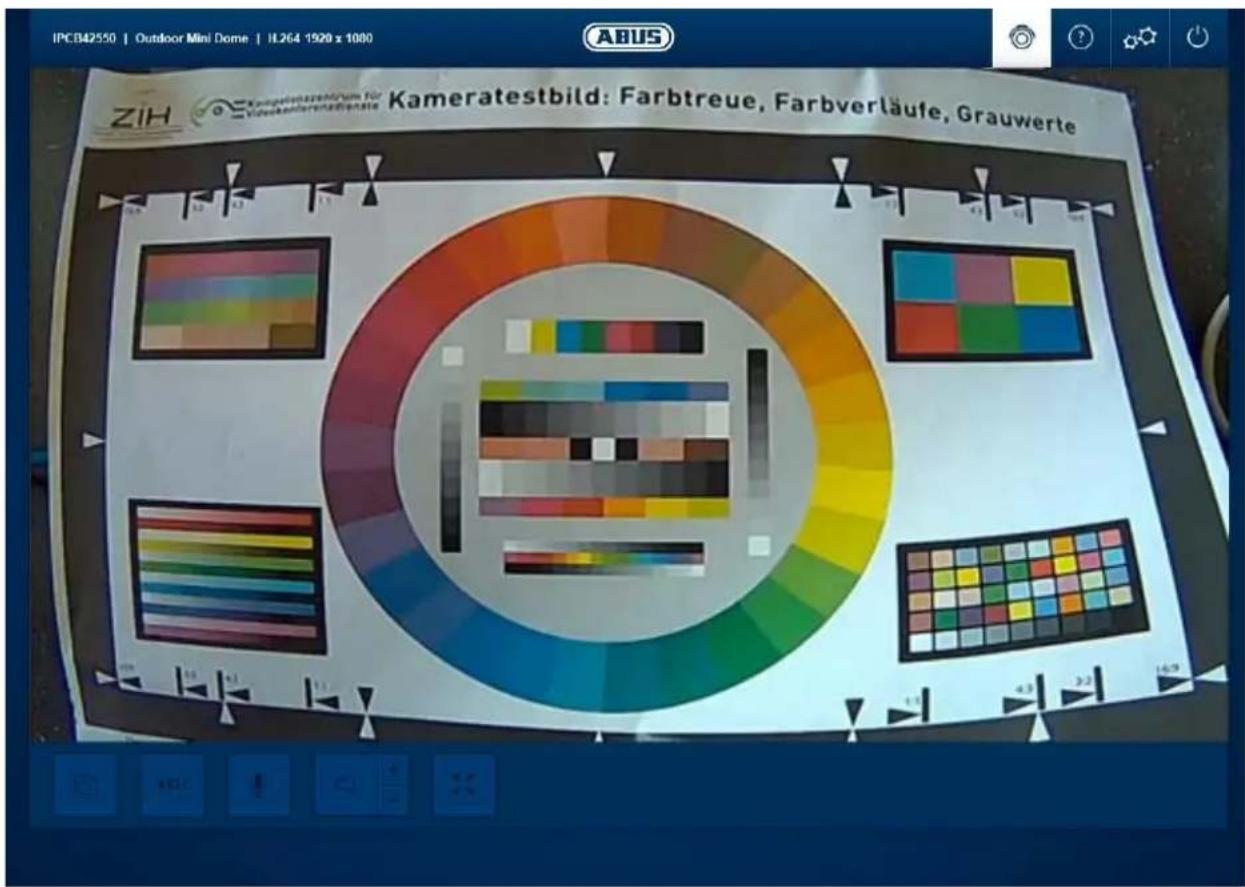
7. View and configuration menus user "installer"
7.1 Live view
The live view display for the installer user is similar to that of the master user. However, the installer user has extended options for settings such as the set up wizard or extended configuration.
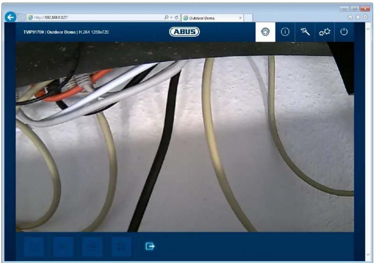
(Example image: IPCB42550)
7.2 Help page
The functions of the buttons on the live page are explained on this page.
7.3 Info page
The info page displays general information about the camera, e.g. installed firmware version or MAC address of the camera.

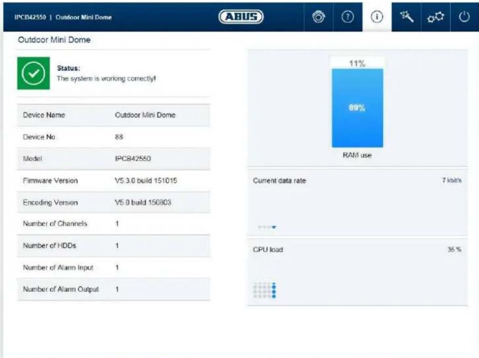
In the area to the upper left, the general status of the system is represented by a symbol.
| System is running correctly All parameters such as system temperature and processor usage are fine. All functions in use are working correctly. | |
| System is faulty Errors have occurred in the system. But these are not critical to the basic functionality of the camera. However, they could cause limitations or malfunctions within certain functions. The system may need to be tested by the installer. | |
| System condition is critical Certain parameters such as system temperature or processor usage are critical for the system. The system must be tested by the installer immediately. |
IP camera name: display of the camera name. Can be modified using Configuration/System
Device number: display of the max. resolution of the camera platform.
Model: camera item number
Firmware version: display of the firmware version currently installed
Encoding version: version number of the video encoder
Number of Channels: Typically, only 1 channel is shown for a camera. A number of camera channels may be available for IP encoders.
IP address: display of the IP address currently set
Number of HDDs: display of the number of installed storage media (e.g. microSD card)
Number of Alarm Input: number of switching inputs on the camera
Number of alarm outputs: number of switching outputs on the camera
Memory usage: internal memory status
Data throughput: total video and audio bit rate over the network interface (outgoing)
CPU usage: display of the processor usage of the camera.
7.4 Setup wizard
The setup wizard navigates you through the most important menu options the camera has. The setup wizard deals with the following menu options:
Network DDNS Text Date/time Installer Service Storage/Restart

For more information on each settings option see the section "Advanced camera settings".
7.5 Advanced camera settings
7.5.1 Video
7.5.1.1 Image
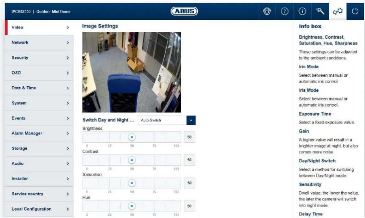
Brightness, contrast, saturation, hue: Adjust these values to suit the ambient conditions. Sharpness: set the electronic oversharpening for the image (edge overdraw)
Iris mode: choose between manual and automatic iris control, depending on your model. If only one mode is available, then it is the only mode offered.
Exposure time: select a value for the fixed exposure time.
Gain: The higher the value is, the lighter the image is in poor lighting conditions and therefore the higher the image noise is.
Day/night switching: select a method for switching between day and night mode. Day: the camera stays in day mode. Night: the camera stays in night mode. Auto: Automatic switching according to light conditions Schedule: switching at fixed times. You must enter the day start time and day end time. Triggered by event: switching is performed by triggering the switching input. The output status can be achieved via the status option if the input is not triggered.
Sensitivity: Switching threshold: the lower the value, the later the camera switches to night mode.
Switch time: delay in seconds until switching to day or night mode.
Overexposure protection: prevents glare effects from objects that are too close when IR lighting is enabled.
BLC: backlight compensation with reference to a selected area
WDR: wide dynamic function for improved display of high contrasts.
The WDR level should be reduced if the image displayed is too bright.
Wide dynamic level: select the WDR level. A higher level may increase image noise.
White balance: you can select between different variants of white balance.
Digital Noise reduction: function to reduce noise in the image. The higher the value, the
more noise is removed and the more static the image appears.
Noise reduction level: select the DNR level
Mirroring: this setting can be used to mirror the image horizontally or
horizontally and vertically.
Video standard: Here you can set the mains frequency of the power supply
network.

The effective IR range will depend on the installation location. If there are surfaces that absorb light or no objects that reflect IR light in the field of view, the IR range will be reduced and/or the video image will be too dark.
Reflective objects in the immediate vicinity of the camera (e.g. roof gutter or wall) may also result in the reflection of IR light, which can disturb the image.
7.5.1.2 Privacy masking
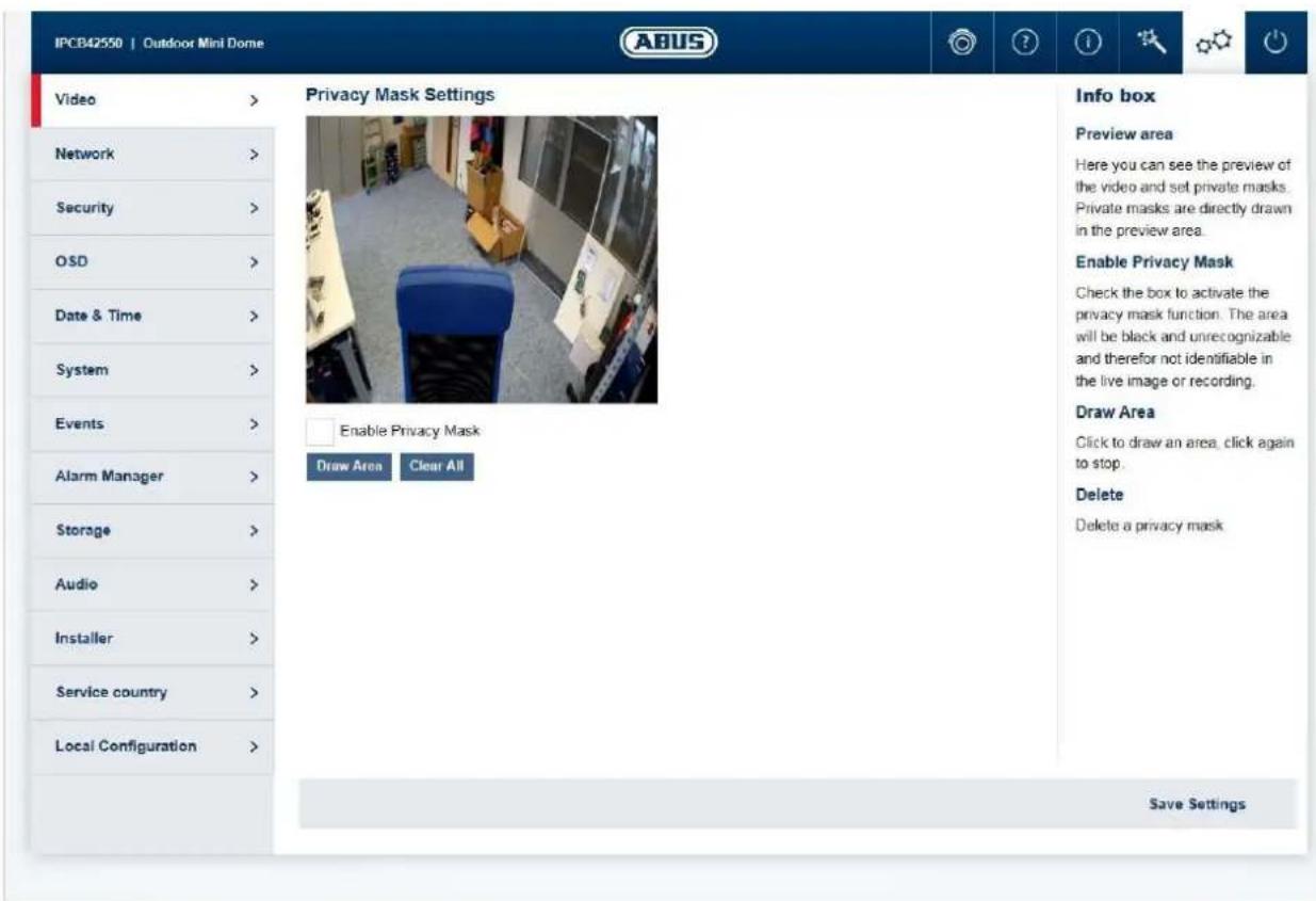
Preview area: the preview of the video and privacy masks that have been set up are displayed here. Privacy masks are drawn directly in the preview area.
Enable privacy mask: enable/disable the privacy masks function.
Draw Area: draw polygonal areas. The drawing mode is closed by clicking this button again. The area drawn is blacked out and so cannot be seen in the live image or in the recording.
Delete all: delete a privacy zone mask
7.5.1.3 Video stream
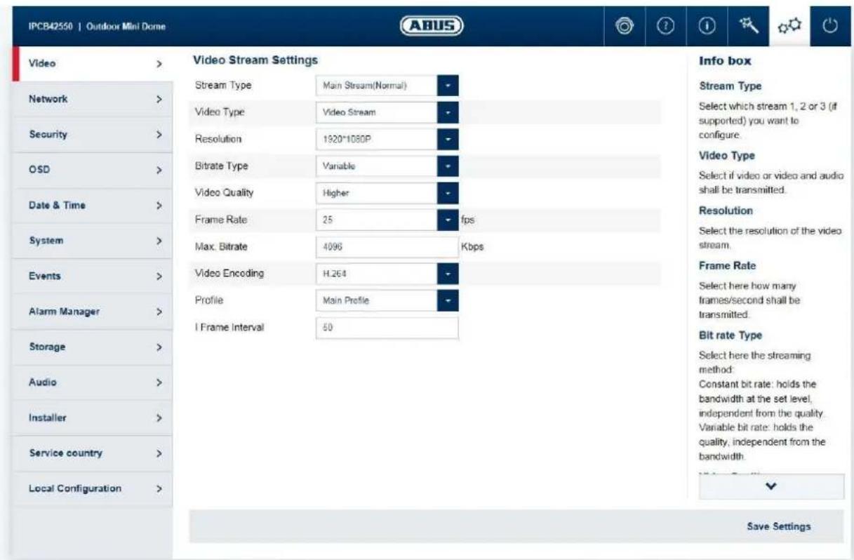
Stream Type: Select the first, second or - if it is available for your camera model - the third video stream for configuration.
Video type: Select whether video or video and audio should be transmitted.
Resolution: choose the resolution for the video stream.
Bitrate type: select the streaming method: Constant bitrate: keeps the bitrate constant at the set value, regardless of the quality.
Video quality: select the desired quality (for variable bitrate only). The value set here describes the compression level.
Frame rate: select the number of images/second to be transmitted.
Max. bitrate: select the bandwidth that should constantly be used for data transmission (for constant bitrate only).
Video encoding: select the codec that should be used for compressing the data.
Profile: here you can select the profile type for the video codec. A profile is standardised and determines the parameters that should be used for encoding.
I frame interval: select how often an I frame should be sent (H.264 only). The more often an I frame (full image) is sent, the better the video quality is, but the more bandwidth is required.
7.5.2 Network
7.5.2.1 IPv4/IPv6 settings
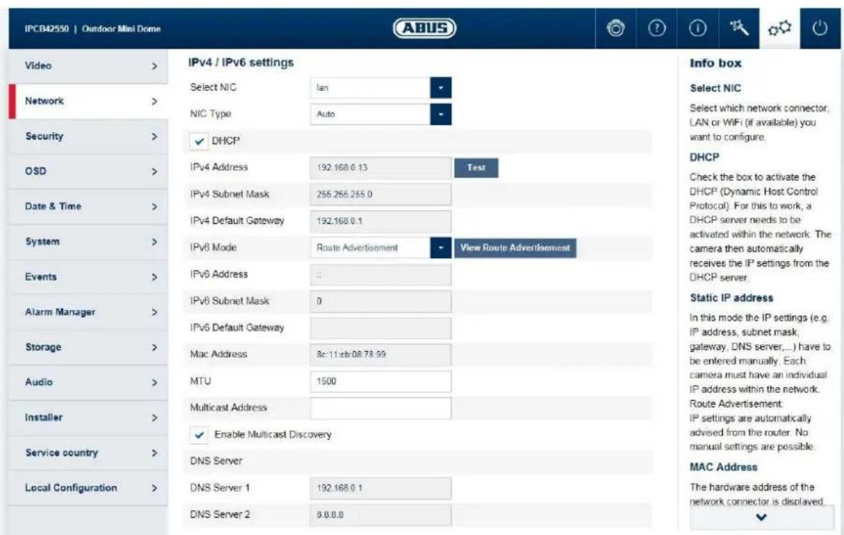
Select NIC: choose whether the LAN or WLAN interface (if available) should be configured.
NIC type: selection of the speed for the LAN adapter.
DHCP: the IP address, subnet mask, gateway (default router) and address for the DNS server are obtained automatically from a DHCP server. An activated DHCP server must be present in the network in this case. The fields on this page are deactivated in this mode and serve as informational fields for the data obtained. If DHCP is not enabled, then a static IP address is used (see below).
Static IP address: manual setting of the network parameter for IPv4.
IP address: manual setting of the camera's IP address
Subnet mask: manual setting of the camera's subnet mask
Gateway: manual setting of the camera's gateway IP address (also known as default router)
IPv6 mode: Manual: manual allocation of the IPv6 address
DHCP: automatic allocation of the address by the DHCP Route advertisement:
IPv6 address: IPv6 network address
IPv6 Subnet Mask: IPv6 Subnet Mask
IPv6 Default Gateway: IPv6 Default Gateway
MAC Address: display of the MAC address
MTU: maximum packet length
Multicast address: multicast network address
Enable multicast: enable the multicast function
Preferred DNS Server: manual setting of the DNS server's IP address
Alternate DNS Server: alternative IP address of a DNS server
7.5.2.2 Ports
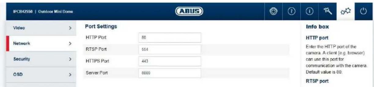
HTTP port: the default port for HTTP transmission is 80. If several IP cameras are
located on one subnet, each camera should have its own unique HTTP port.
RTSP port:
the default port for RTSP transmission is 554. If several IP cameras are located on one subnet, each camera should have its own unique RTSP port.
HTTPS port:
The default port for HTTPS transmission is 443. If several IP cameras are located on one subnet, each camera should have its own unique HTTPS port.
SDK port:
The default port is 8000. If several IP cameras are located on one subnet, each camera should have its own unique SDK port.

If the camera is to be accessed via routers (e.g. from the internet to the local network), port forwarding must be set up for the HTTP, RTSP and SDK port in the router. If HTTPS is also being used, port forwarding must be set up for the HTTPS port too.
7.5.2.3 DDNS
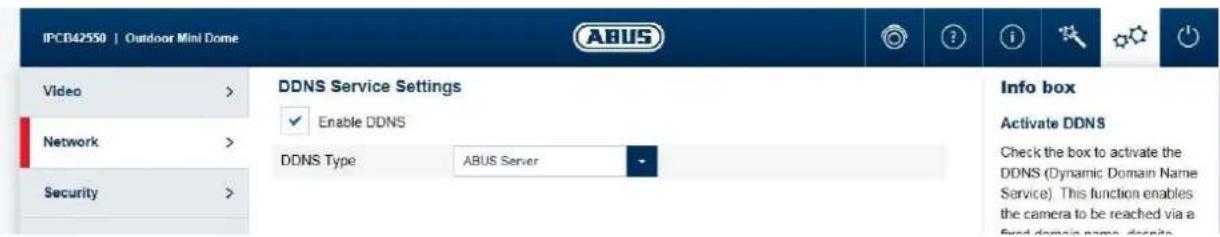
Activate DDNS: ticking the checkbox activates the DDNS function. Select service: select a service provider for the DDNS service.
Server Address: IP address of the service provider
Domain: registered host name with the DDNS service provider
Port: port for the service
User name: user account identification with the DDNS service provider
Password: account password with the DDNS service provider

Further information on the "ABUS SERVER" can be found on the help page at the following address: https://www.abus-server.com/faq.html
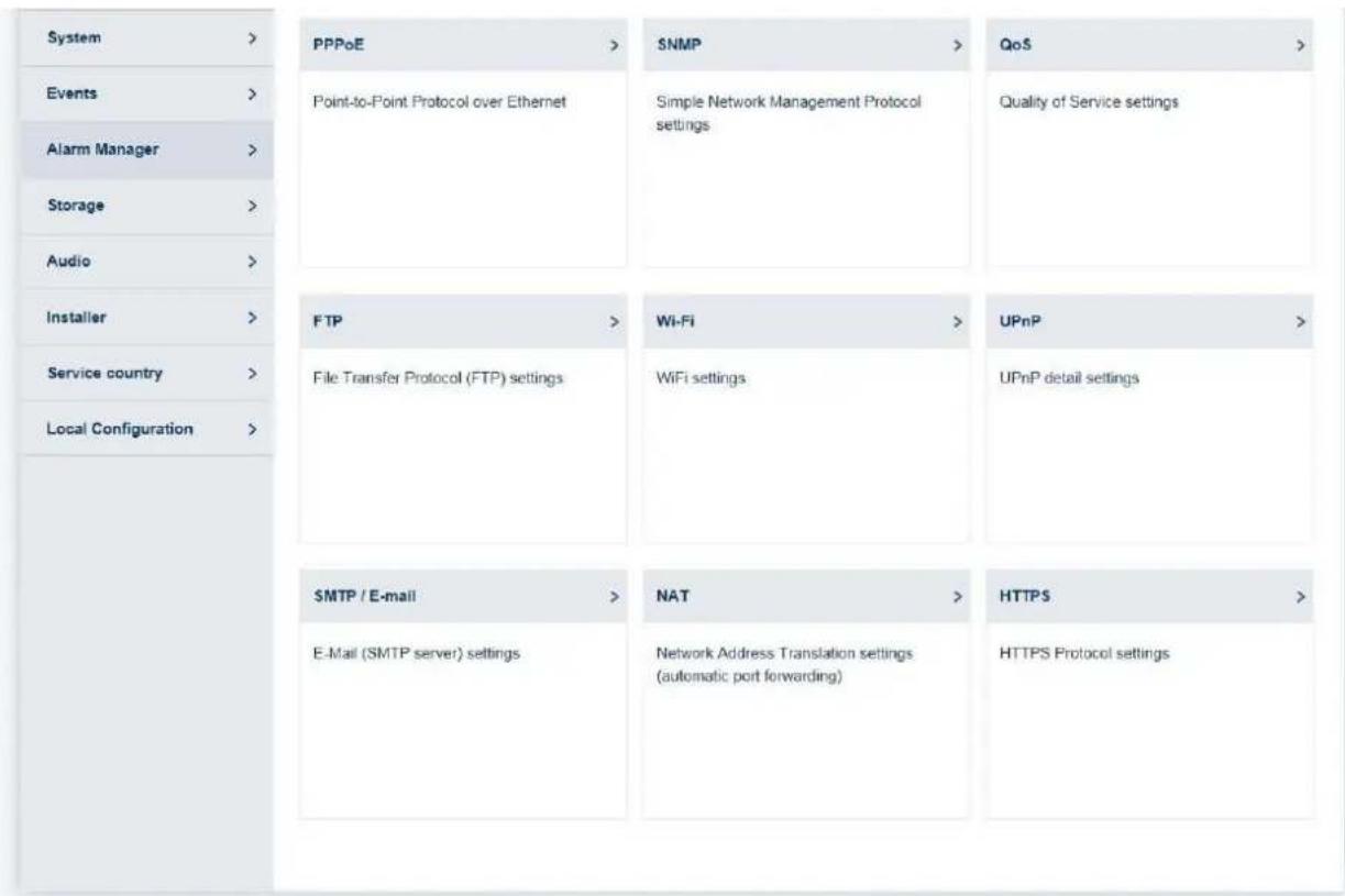
7.5.2.4 PPPoE
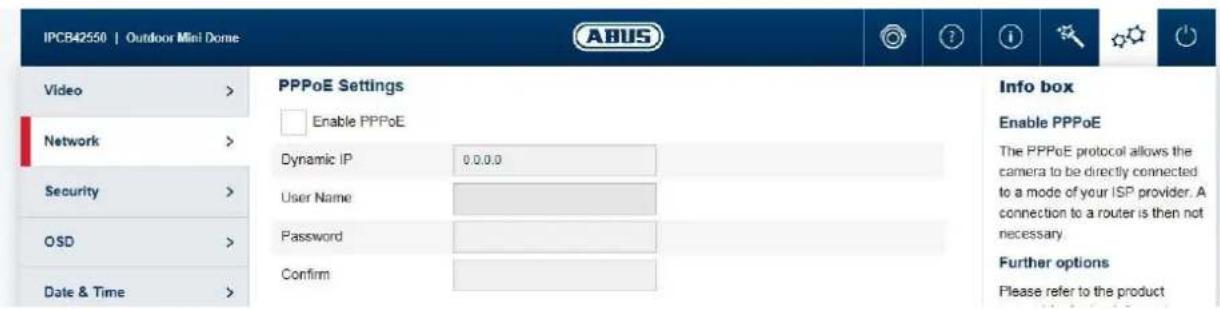
The PPPoE protocol makes it possible to connect the camera to a provider modem directly. An additional router is not required.
Enable PPPoE: enable the PPPoE function
Dynamic IP: display of the dynamically determined public IP address
User name: input of the user name from the provider (ISP)
Password: input of the password from the provider (ISP)
Confirm: Password confirmation
7.5.2.5 SNMP
SNMP (Simple Network Management Protocol)
The SNMP protocol enables central network management of network components.
Enable SNMPv1: enable the SNMPv1 function
Enable SNMPv2: enable the SNMPv2 function
Write SNMP Community: SNMP Community string for writing
Read SNMP Community: SNMP Community string for reading
Trap Address: IP address of the TRAP server
Trap Port: Port of the TRAP server
Trap Community: TRAP Community string
Enable SNMPv3: Enabling of SNMPv3
ReadUserName: Allocate user name
Security level: auth, priv: no authentication, no encryption
auth, no priv.: authentication, no encryption
no auth, no priv.: No authentication, encryption
Authentication algorithm: Select authentication algorithm: MD5, SDA
Authentication Password: Password assignment
Private-key Algorithm: Select encryption algorithm: DES, AES
Private-key password: Password assignment
WriteUserName: Allocate user name
Security level: auth, priv: no authentication, no encryption
auth, no priv.: authentication, no encryption
no auth, no priv.: No authentication, encryption
Authentication algorithm: Select authentication algorithm: MD5, SDA
Authentication Password: Password assignment
Private-key Algorithm: Select encryption algorithm: DES, AES
Private-key password: Password assignment
SNMP Port: Network port for the SNMP service
7.5.2.6 QoS
QoS determines the data flow between two network components on the basis of quality parameters.
DSCP - Differentiated Service Code Point
Video/Audio DSCP: DSCP value for video/audio data
Event/Alarm DSCP: DSCP value for event/alarm data
Management DSCP: DSCP value for the communication data
7.5.2.7 FTP
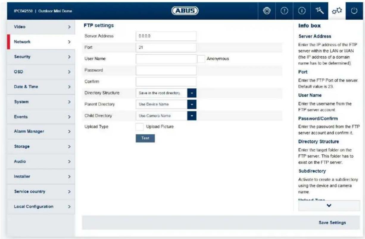
Server Address: IP address of the FTP server
Port: FTP server port
User name: user name for the FTP server account
Anonymous: anonymous access to the FTP server (server must support this)
Password: password for the FTP server account
Confirm: Password
confirmation
Directory Structure: Select the save location for the uploaded data here. You can choose between "Save in the root directory."; "Save in the parent directory"; "Save in the child directory".
Parent directory: This menu item is only available if "Save in the parent directory" or "Save in the child directory" was selected under Directory Structure. You can select the name for the parent directory here. The files are saved in a folder on the FTP server. Choose between 'Use Device Name', 'Use Device Number' and 'Use Device IP address'.
Child directory: Select the name for the child directory here. The folder is created in the parent directory. You can choose between 'Use Camera Name' or 'User Camera Number'.
Image archiving interval: Options: OFF, 1-30 days
This value specifies how often a new folder is created for storing the images on the FTP server (example: value 1 -> a new folder for the storage of the images is created every day).
Ensure that the user created on the FTP server has rights to create folders.
Image name: Default: IP_Kamerakan_Zeitstempel_Ereignistyp.jpg
Custom prefix: Prefix_ID_time stamp_Ereignistype.jpg
Upload picture: Select 'Upload Picture' to upload pictures to the FTP server.
Test: Button for testing the FTP settings
7.5.2.8 Wi-Fi (only IPCB42551)
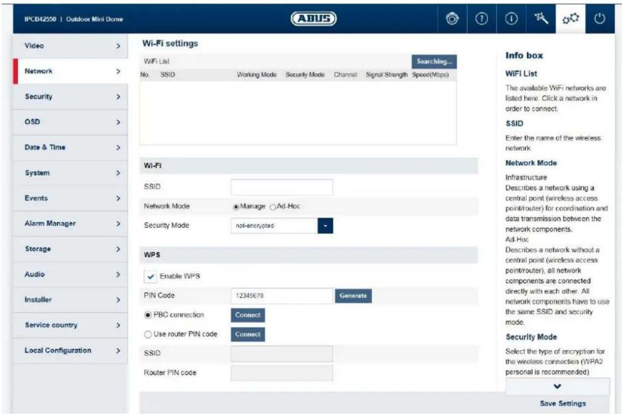
Wi-Fi list: Available Wi-Fi networks are displayed here. Click in a row to select a network.
SSID: (Service Set Identifier) Enter the name of the wireless network here.
Network mode: Infrastructure
Describes a network in which a central instance (wireless access point/rodter) carries out the coordination and data transmission for all network components.
Ad hoc Describes a network in which all network components are connected to one another directly, without using a central instance (wireless access point/rodter). All network components must use the same SSID and security mode.
Security mode: Select encryption for the Wi-Fi connection (WPA2 personal is recommended).
Encryption Type: Select an encryption algorithm.
Password: Enter a password for the Wi-Fi network.
Enable WPS: (Wi-Fi protected setup) enables the WPS function. There are 2 different methods for using the WPS function (PIN code, PBC).
PIN code: generates a new PIN code for using the PIN code method.
PBC connection: (Push Button Configuration) the WPS connection is produced after a button is pressed on the camera.
PIN code connection: a PIN code is generated in the router and entered in the camera.
7.5.2.9 UPnP
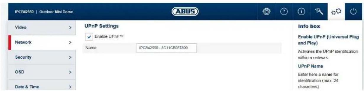
Enable UPnP: For enabling or disabling the UPnP function.
Friendly name: assigning a UPnP name, which the camera uses to appear on the network via UPnP.
7.5.2.10 SMTP/Email
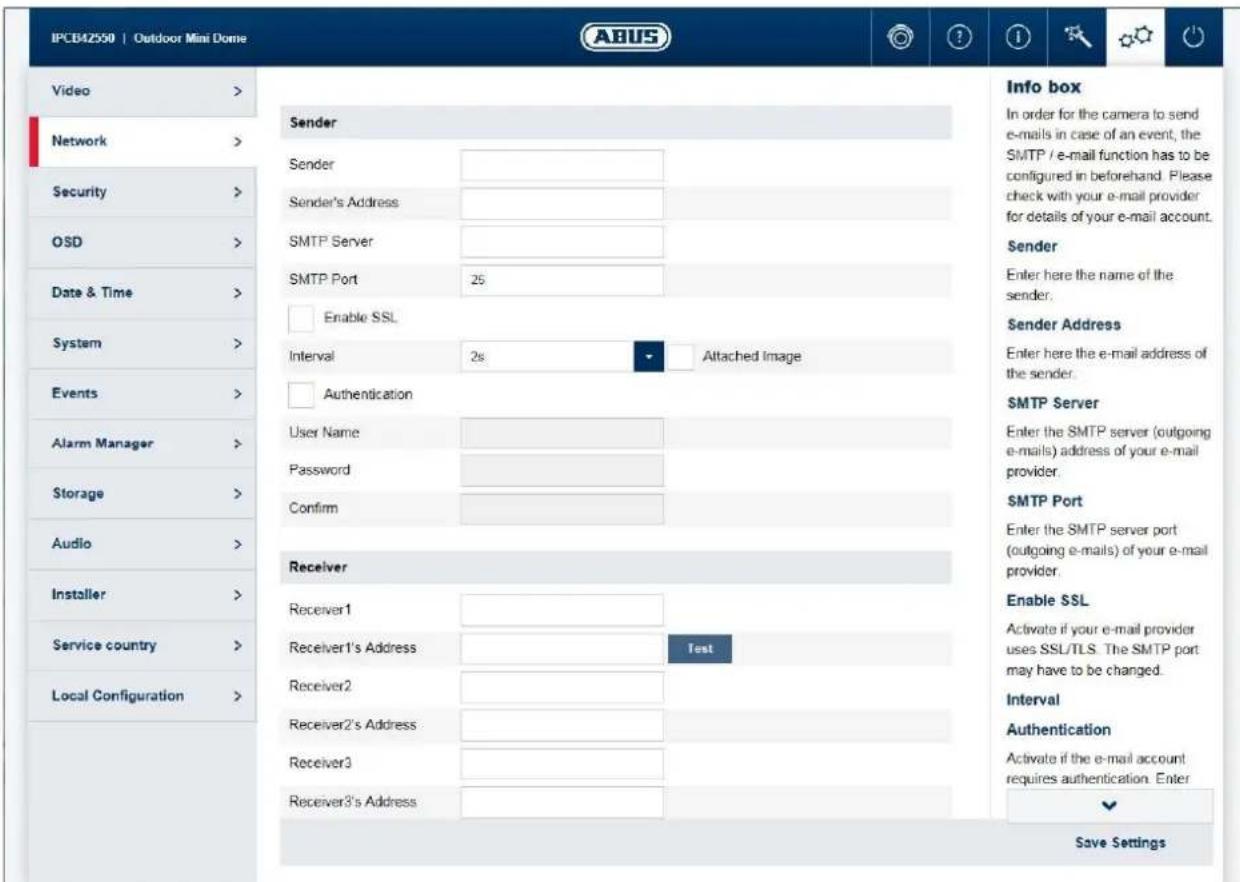
The SMTP/email function must be configured beforehand, so that the camera is able to send emails if certain events occur. You can obtain information about the various details from your email provider.
Sender: Enter the name of the sender here.
Sender's address: Enter the email address of the sender here.
SMTP Server: Enter the SMTP outgoing mail server for your email provider here.
SMTP port: Enter the SMTP server port here (e.g. 587 if you are using TLS). I.
Enable SSL: enable if the email server uses SSL or TLS. The SMTP port may have to be changed.
Interval/attached image: Choose an image interval for attached images. /Option must be enabled for attached images.
Authentication/
```bash User name/
Password: Enable this option if the SMTP email server requires authentication. Enter the user name and password and confirm the password for the account for sending email.
Recipient/recipient address: Enter the email recipients with name and email addresses (max. 3 recipients) here.
7.5.2.11 NAT
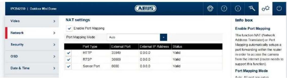
Enable port mapping: The NAT (Network Address Translation) or port mapping function automatically sets up port forwarding for access from the Internet to the camera in the router (if the router supports this).
Mapping type: Auto: automatic assignment of all ports
Manual: manual assignment of all ports
7.5.2.12 HTTPS
Activate HTTPS: enables the HTTPS function. This enables a secure connection with connection certificate. Please note that further steps are necessary for configuring the HTTPS function.
Create a self-signed certificate: enter all of the details required for the certificate. When accessing the camera at a later point, the connection must also be confirmed in the browser.
Install a signed certificate: install a HTTPS certificate from an external provider. When accessing the camera at a later point, the connection is automatically accepted as secure (address bar shows green).
7.5.3 Security
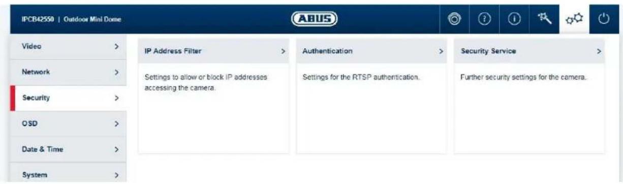
7.5.3.1 IP address filter
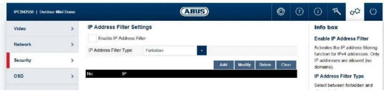
Enable IP address filter: enables the IP address filter function for IPv4 addresses. Only IP addresses are allowed when inputting the addresses (no domain names).
IP address filter type: choice between forbidden and allowed addresses.
Add/
Modify/
Delete: manage filter rules. The format for entering an IP address is:
XXX.XXX.XXX.XXX
7.5.3.2 Authentication
RTSP authentication: On (basic): enables authentication. User name and password are required for transmitting video data via RTSP. Off (disable): disables authentication.
7.5.3.3 Security service settings
Enable illegal login lock: after enabling, access to the camera is locked for 5 minutes if the user name or password is input incorrectly 3 times.
7.5.4 OSD
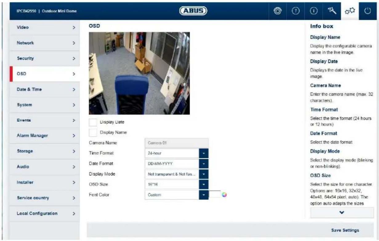
Display name: superimposes the configurable camera name on the live image.
Display date: superimposes the date on the live image.
Camera name: enter the camera name here (max. 32 characters).
Time format: select a display format (24-hour or 12-hour) for the time.
Date format: select a display format for the date.
Display mode: select between flashing or non-flashing display for all overlays.
OSD size: select the size for a character. Options: 16x16, 32x32, 48x48,
64x64 pixels, auto). The auto option automatically adapts the character size to the image size.
Font colour: select the colour for displaying characters. The colour palette for a custom selection can be found on the right next to the selection box.
7.5.5 Date & time
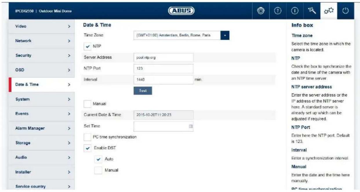
Time zone: here, select the time zone in which the camera is located.
NTP: tick the box to synchronise the date and time of the camera with an NTP time server.
Server address/NTP port: enter the server address or the IP address for the NTP server here. A standard server is already set up and can be adjusted if required.
NTP port: enter the NTP port here. The standard port for NTP is 123.
Interval: select an update interval.
Manual: manual setting of date and time. Click in the date/time field to open a configuration menu.
Synchronisation with computer time: use the current PC time currently being used for access (after saving the settings).
Enable summer time (DST): tick the box if there is generally a summer time/winter time changeover at the camera location.
7.5.6 System
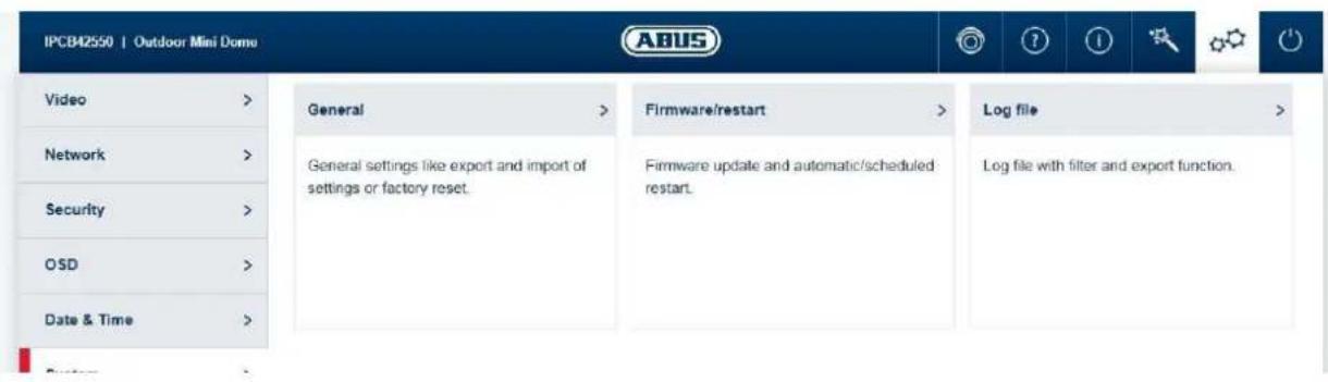
7.5.6.1 General
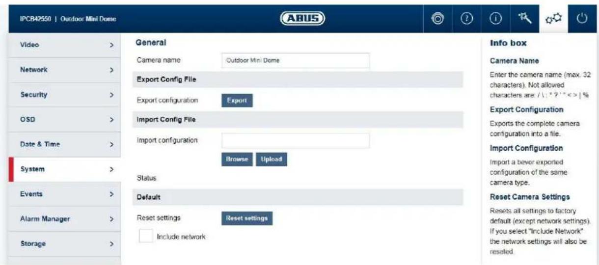
Camera name: enter a name here (max. 32 characters). Forbidden
characters are: \ / : * ? ! < > | %
Export configuration: exports the entire camera configuration into a file.
Import configuration: imports a previously exported configuration of the same
camera type.
Reset settings: resets the camera to factory settings (except network
settings). Selecting "Include network" also resets the network settings.
7.5.6.2 Firmware/Reset
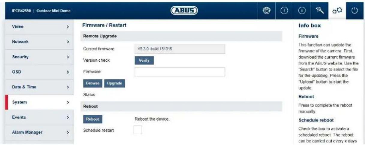
Firmware/remote upgrade: This function can be used to update the camera's firmware. First, download the current firmware from the ABUS website. The "Search" button can be used to select this file for updating. Press the "Upload" button to start the update.
Restart: Press the "Reboot" button to complete the restart manually.
Reboot schedule: enables scheduled reboot. The reboot can be carried out
every x days at a certain time.
7.5.6.3 Log file
Log file: data relevant to the system is recorded in the log file. This can help with troubleshooting, for example.
Export: exporting the log file into another file
7.5.7 Events
7.5.7.1 Motion detection
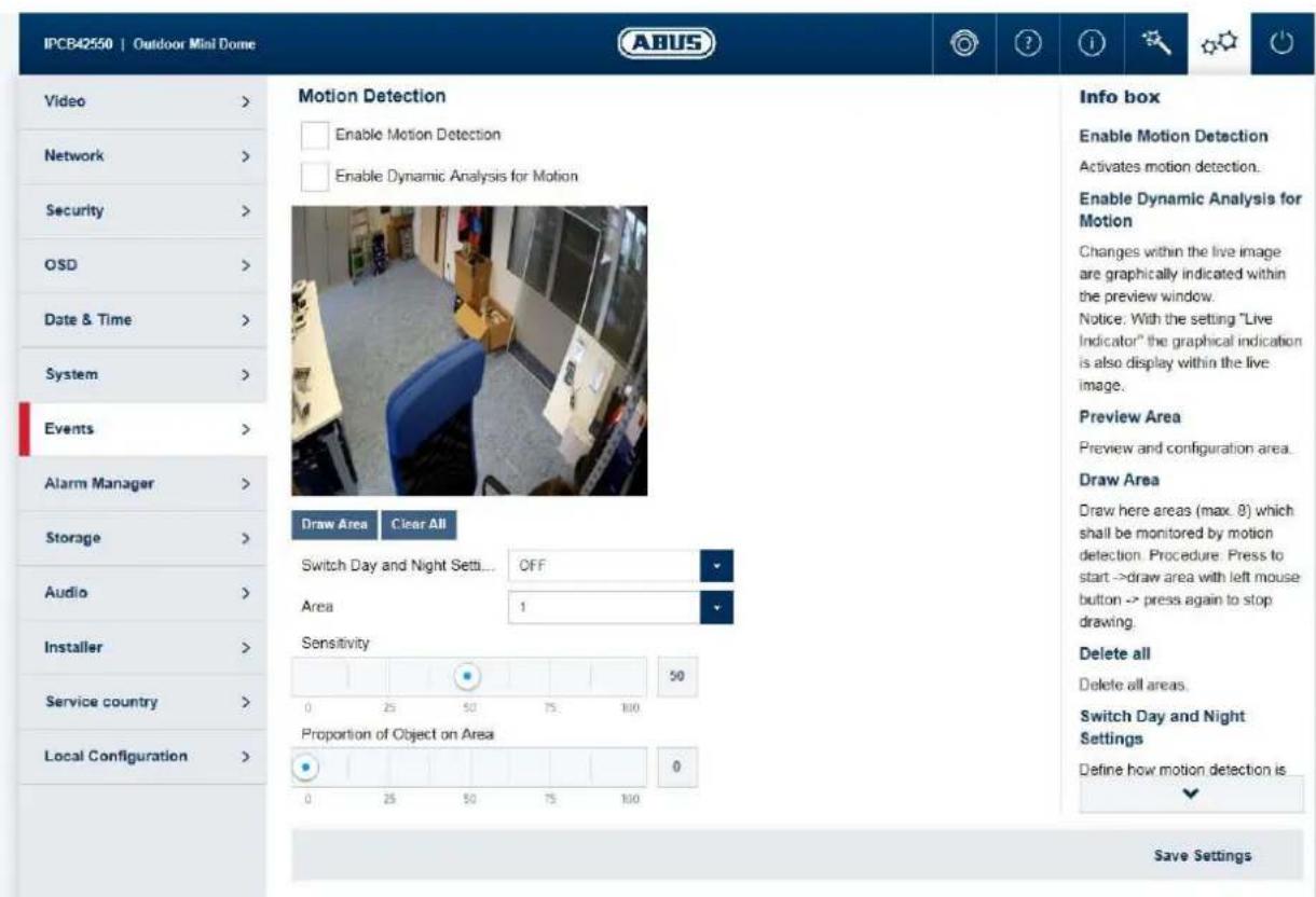
Enable motion detection: enables motion detection.
Enable dynamic analysis for motion: if enabled, changes to the video image content are
displayed graphically in the preview.
NOTE: The LIVE INDICATOR function decides whether this should also be displayed in the live image.
Preview area: preview and configuration area.
Draw Area: draw areas here (max. 8), which should be monitored by motion
detection. Operation: Press button -> draw rectangle in the preview using left mouse button -> press button again to finish drawing.
Delete all: delete all areas.
Day/night switching: defines how motion detection is applied during the day or night mode.
Off: settings for day and night are identical.
Automatic switching: settings are automatically coupled to automatic
day/night switching.
Schedule: settings for day and night are applied according to a
schedule.
Sensitivity: determines the required intensity of the pixel change. The higher
the value, the fewer pixel changes are required to trigger motion.
Proportion of object on area: object size required for triggering motion in the area (0-100%).
7.5.7.2 Cover Detection
Enable Cover Detection: This function detects if an area within the live image is covered.
Preview Area: Preview and configuration area.
Draw Area: Draw here an area which shall be monitored by tamper detection.
Procedure: Press to start -> draw area with left mouse button -> press again to stop drawing.
Delete: Delete the area.
Sensitivity: Change the sensitivity of the detection (3 levels).
7.5.7.3 Alarm input (only IPCB42551)
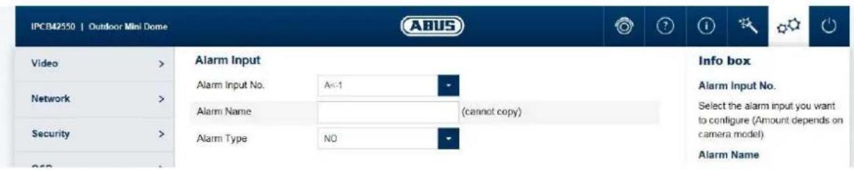
Alarm input: Select the alarm input to be configured here (number depends on camera model).
Alarm name: enter the name here.
Alarm type: the alarm type determines the idle and triggered statuses.
NO: normally open (normal status open)
NC: normally closed (normal status closed)
7.5.7.4 Alarm output (only IPCB42551)
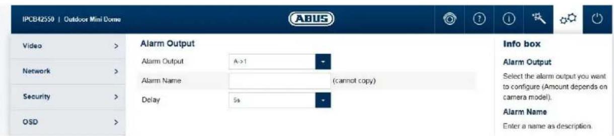
Alarm output: Select the alarm output to be configured here (number depends on camera model).
Alarm name: enter the name here.
Dwell time: select the duration of switching output activity in the event of an alarm.
Manual: The output is only activated for as long as the event lasts.
7.5.8 Alarm manager
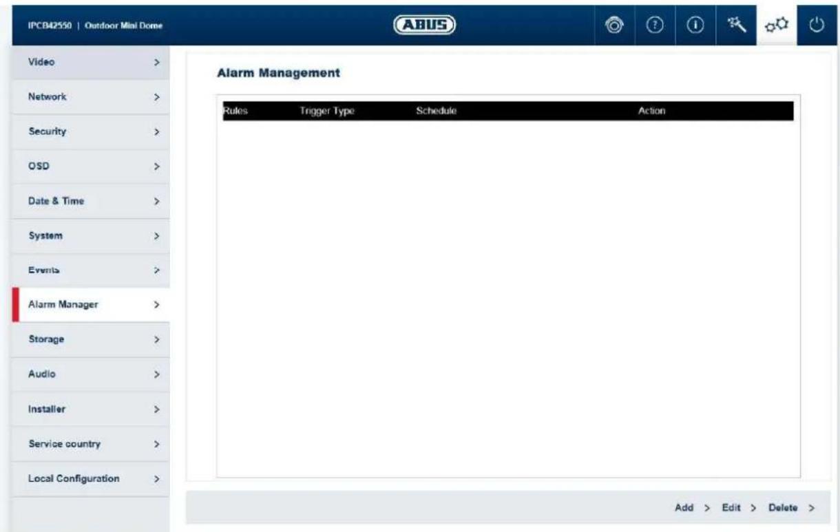
Trigger: an alarm rule consists of a trigger, a schedule for applying the rule and an action. Select a trigger for the alarm rule from the list. Only one trigger can be configured for each rule.
Schedule: an alarm rule can be enabled in 30 minute intervals. This is highlighted directly in the matrix on the left (red = enabled).
Delete all: deletes the entire schedule.
Mark all: selects the entire schedule.
Action: one or more actions can be defined for the rule on this page.
7.5.9 Recording
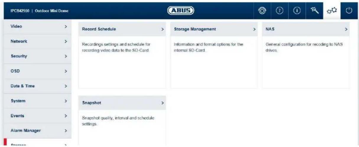
7.5.9.1 Recording schedule
This is where the recording of video files to SD card or NAS drive is configured.

The recording can be done either on SD card or NAS drive. When an SD card is installed in the camera, the SD card is used exclusively. The SD card must be removed for recording on a NAS storage drive.
Post-record: determine how long a video should be saved for after an event.
Overwrite: determine the behaviour if an SD card is full (end recording or
replace oldest data with new data = cycle recording function).
Video stream: Select the video stream for recording.
Enable record schedule: after enabling and configuration, video data are either saved
constantly or at certain times and if necessary when an event
occurs. The schedule can be configured using the Edit button.
7.5.9.2 Storage management
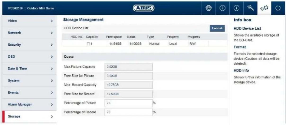
Device list: indicates the available storage media in the camera (SD card).
Format: formats the selected storage medium (Attention: all data are deleted).
Information: shows more storage medium information.
7.5.9.3 NAS
NAS: configure up to 8 NAS devices. Click in a row to specify server address, file path, server type, user name and password.
7.5.9.4 Snapshot
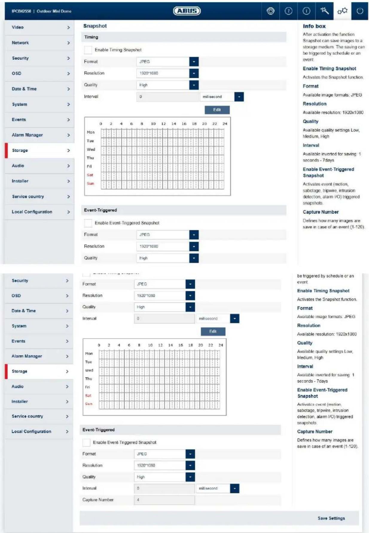
After enabling and configuration, single frames can be saved on the SD card. The single frames can be saved in a time-controlled and/or event-controlled manner.
Enable snapshot timing: enables time-controlled storage.
Format: available image formats for the single frames: JPEG
Resolution: available resolutions for the single frames: 1920x1080
Quality: available quality for the single frames: 3 levels
Interval: you can determine the save intervals (min. 1 second, max. 7
days) here.
Edit schedule: You can determine the schedule for storage here.
Enable event-triggered snapshot: after enabling, single frames are saved to the
SD card if an event occurs (e.g. motion
detection, cover detection)
Number of images: here you can define the number of images saved after an
event (1-120).
7.5.10 Audio (only IPCB42551)
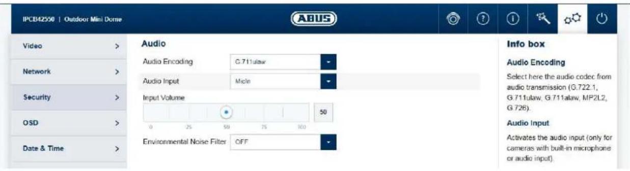
Audio encoding: select the audio encoding for audio transmission here (G.722.1, G.711ulaw, G.711alaw, MP2L2, G.726).
Audio input: enables the audio input (only for cameras with built-in microphone and microphone input).
Input volume: adjustment of the input amplification for the microphone.
Environmental noise filter: enable the digital noise reduction function for audio transmission here.
7.5.11 Installer
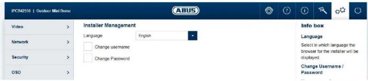
Language: here you can specify the language used for the camera menu for the installer in the browser.
Modify user name/password: Modify the user name and password for installer access here. The default user name for this is "installer", the default password is "installer".

The home page and login window are displayed in the language of the PC as long as this language is available in the camera. If the language is not available, it will be displayed in English.
7.5.12 Service
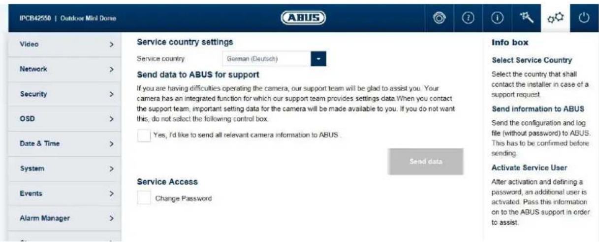
Country of service: select the country where the installer of the camera will be contacted in the event of service.
Send information to ABUS: sends the configuration file (without passwords) and the log file to ABUS support. This confirmation must be confirmed before sending.
Enable service account: after enabling and password submission, an additional account is enabled, which can be sent out for ABUS support.
7.5.13 Local configuration
Protocol: Setting the transmission protocol (default: TCP)
Live view performance: Select the priority for display in the browser here (priority on image stream or image quality).
Live indicator: Display of all event animations in the live image (e.g. frame for motion detection). These animations are also recorded to the recording device.
Image format: Select the encoding format for saving single frames using the browser live interface.
Record file size: Select the size of video sequences for saving videos using the browser live interface.
Save record files to: Select the path for video recording.
Save downloaded files to: Select the path for video files downloaded from the SD card.
Save live snapshots to: Select the encoding format for saving images using the browser live interface.
Snapshots during playback: Select the path for saving images during playback.
Save clips to: Select the path for saving video clips during playback.
8. Maintenance and cleaning
8.1 Function test
Regularly check the technical safety of the product, e.g. check the housing for damage.
If it appears to no longer be possible to operate the product safely, stop using it and secure it to prevent unintentional use.
It is likely that safe operation is no longer possible in the event that:
- the device shows signs of visible damage
the device no longer works correctly - the device has been stored in adverse conditions for a long period of time
- the device has been exposed to stresses during transportation.

Please note:
You do not need to perform any maintenance on the product. There are no components requiring servicing or checking inside the product. Never open it.
8.2 Cleaning
Clean the product with a clean, dry cloth. The cloth can be dampened with lukewarm water to remove stubborn dirt.

Make sure that no liquids enter the inside of the device, as this will destroy it. Do not use any chemical cleaning agents, as these could damage the surface of the housing.
9. Disposal
Devices displaying this symbol may not be disposed of with domestic waste. At the end of its service life, dispose of the product according to the applicable legal requirements.
Please contact your dealer or dispose of the products at the local collection point for electronic waste.
IPCB42501 / IPCB42551
Chere cliente, cher client,
Chere cliente, cher client,
6.3 Configuration locale
DSCP - Differentiated Service CodePoint
IPCB42501 / IPCB42551

| True | WDR | WDR | ||
| IPCB42501 | - | √√ | - | |
| IPCB42551 | - | √ | √ | √ |

4.7 Camera integreren in ABUS VMS / ABUS VMS Express
4.9 Camera integreren in IPCam
Trap Community: TRAP Community string
SNMPv3 activeren: Activering van SNMPv3
DSCP - Differentiated Service CodePoint
IPCB42501 / IPCB42551

| True | WDR | WDR | ||
| IPCB42501 | - | √√ | - | |
| IPCB42551 | - | √ | √ | √ |

4.4 Installation of video-plugin
Internet Explorer
4.5 Startside (login-side)
Nár IP-adressen er indtastet i browserens adresselinje, og widen er abnet, vises startsiden på sproget for sprogindstillingen for Internet Explorer (Windows-indstilling).
Den enkelte brugerkonto (installer, master erer user) kan indstilles individuelt pa sproget.
Ekempelvis kan indstillingssiderne for "installer" vises på engelsk og websiderne for "master" på tysk.
Hvis billedt vises for lys, skal WDR-trinnet reduceres.
Route advertisement:
DSCP - Differentiated Service CodePoint
Video/audiosDSP: DSCP-vaeri for video-/audiodata
Haendelse/alarm DSCP: DSCP-vaeri for haendelses-/alarmdata
NC: Normally Closed (normaltilstand lukket)
These operating instructions are published by ABUS Security-Center GmbH & Co.KG, Linker Kreuthweg 5, 86444 Affing, Germany. No reproduction (including translation) is permitted in whole or part e.g. photocopy, microfilming or storage in electronic data processing equipment, without the express written consent of the publisher.
The operating instructions reflect the current technical specifications at the time of print.
We reserve the right to change the technical or physical specifications.


- IPCB42501 / IPCB42551
- User manual Software
- IPCB42501
- IPCB42551
- Disclaimer
- Important safety information
- Dear Customer,
- Contents
- MAINTENANCE AND CLEANING 110
- DISPOSAL 110
- Intended use
- Explanation of symbols
- Features and functions
- Initial start-up
- Using the ABUS IP Installer for camera search
- Accessing the network camera using a web browser
- General instructions for using the settings pages
- Installing a video plugin
- Mozilla Firefox
- Google Chrome
- Homepage (login page)
- User accounts and passwords
- Request to change the default password
- Linking up the camera with ABUS VMS/ABUS VMS Express
- Linking up the camera with ABUS NVR/ABUS Hybrid DVR
- Linking up the camera to IPCam
- User menu "user"
- View and configuration menu user "master"
- Add/change/delete users
- Deactivate/activate installer access
- Local configuration
- Info box
- Protocol
- Live View Performance
- Live Indicator
- Image Format
- Displaying/downloading video from the internal memory
- View and configuration menus user "installer"
- Live view
- Help page
- Info page
- Setup wizard
- Advanced camera settings
- Video
- Image
- Privacy masking
- Video stream
- Network
- IPv4/IPv6 settings
- Ports
- DDNS
- PPPoE
- SNMP
- QoS
- FTP
- Wi-Fi (only IPCB42551)
- UPnP
- SMTP/Email
- NAT
- HTTPS
- Security
- IP address filter
- Authentication
- Security service settings
- OSD
- Date & time
- System
- General
- Firmware/Reset
- Log file
- Events
- Motion detection
- Cover Detection
- Alarm input (only IPCB42551)
- Alarm output (only IPCB42551)
- Alarm manager
- Recording
- Recording schedule
- Storage management
- NAS
- Snapshot
- Audio (only IPCB42551)
- Installer
- Service
- Local configuration
- Maintenance and cleaning
- Function test
- Please note:
- Cleaning
- Disposal
- Chere cliente, cher client,
- Configuration locale
- Camera integreren in ABUS VMS / ABUS VMS Express
- Camera integreren in IPCam
- Installation of video-plugin
- Internet Explorer
- Startside (login-side)
Brand : ABUS
Model : FUMO50040
Category : Alarm system