
FUBE50061 - Electrical switch ABUS - Free user manual and instructions
Find the device manual for free FUBE50061 ABUS in PDF.
| Product type | Wireless key switch for Secvest alarm control panel |
| Brand | ABUS |
| Model | FUBE50061 |
| Dimensions (H x W x D) | 87 x 117 x 47 mm |
| Weight | 546 g |
| Power supply | Lithium AA 3.6 V battery (included) or continuous 12 V DC power supply |
| Standby consumption | 4 µA (battery) / 15 mA (12 V) |
| Programming consumption | 36 mA (battery) / 90 mA (12 V) |
| Transmission consumption | 33 mA (battery) / 90 mA (12 V) |
| Radio frequency | 868.6625 MHz |
| Max transmission power | 10 mW |
| Protection rating | IP55 (weatherproof housing) |
| Operating temperature | -10 °C to +55 °C |
| Displays | 2 LEDs: red (activation) and green (deactivation) |
| Audible signals | Integrated piezo siren (beeps can be enabled/disabled) |
| Access code | 4 or 6 digits (programmable) |
| Operating modes | 3 modes: 1 (control element + info module), 2 (2WAY), 3 (with rolling code) |
| Compatibility | Secvest FU500X, FU800X, FUAA50XYZ (depending on mode) |
| Cylinder | Euro profile half-cylinder 10/30 ABUS C83 |
| Security | Rolling code (mode 3), tamper contact cover and partition, cylinder anti-pull out |
| Installation | Surface mounting, wall mounting with supplied plugs and screws |
| Maintenance | Annual button check, external cleaning without solvent, battery replacement by installer |
| Warranty | 2 years (excluding batteries) |
| Standards | RED 2014/53/EU, EMC 2014/30/EU, RoHS, WEEE, etc. |
Frequently Asked Questions - FUBE50061 ABUS
User questions about FUBE50061 ABUS
0 question about this device. Answer the ones you know or ask your own.
Ask a new question about this device
Download the instructions for your Electrical switch in PDF format for free! Find your manual FUBE50061 - ABUS and take your electronic device back in hand. On this page are published all the documents necessary for the use of your device. FUBE50061 by ABUS.
USER MANUAL FUBE50061 ABUS
Installation instructions and user manual EN
Installation instructions and user manual

0. Preface
Dear Customer,
Thank you for purchasing this wall-mounted wireless key switch for your Secvest wireless alarm system. This product is built with state-of-the-art technology.
To ensure this condition is maintained and that safe operation is guaranteed, it is your obligation to observe this manual.
Our wireless solutions allow you to safely and comfortably operate the Secvest alarm system. Flexibility and security go hand in hand at ABUS. It is the security that our wireless solutions provide that really allows you to enjoy the convenience they have to offer.
PEACE OF MIND AND SECURITY THANKS TO ROLLING CODE
The Secvest wireless key switch works using secure rolling code technology to provide optimum protection against code scanning and code grabbing and thereby preventing unauthorized access.
We are constantly developing our product range in order to be able to provide our customers with optimal and secure products incorporating state-of-the-art technology. With the new software release of the Secvest wireless key switch, we have implemented and optimised a rolling code procedure.

Note
The wireless key switch works using the rolling code procedure when it is in operating mode 3.
The rolling code procedure is compatible with all Secvest systems (FUAA50XYZ) with up to date firmware (>=v2.00.06) . Further details can be found in this manual.
You can also use this wireless key switch with older Secvest systems:
FUAA50XYZ with software versions <=2.00.00
FU800X
FU500X
Reverse compatibility is provided for, but without the rolling code procedure. Use the added safety features that the Secvest has to offer: for
instance the fact that the key switch can only disarm the system when the entry delay is running.
These instructions contain important installation and operation information. Keep this user manual to consult later. These instructions are part of the product. Make sure that this user manual is transferred if the product is passed on to other persons.
Limitation of liability
Everything possible has been done to ensure that the content of these instructions is correct. However, neither the author nor ABUS Security-Center GmbH & Co. KG can be held liable for loss or damage caused by incorrect or improper installation and operation or failure to observe the safety instructions and warnings. No liability can be accepted for resulting damage. No part of the product may be changed or modified in any way. If you do not follow these instructions, your warranty claim becomes invalid. We reserve the right to make changes to this manual without prior notice. © ABUS Security-Center GmbH & Co. KG, 04/2017
1. Intended use
This wireless key switch allows you to easily arm and disarm your Secvest wireless alarm panel. After the switch is operated, it informs you of the status of your panel.
In addition, the wireless key switch can also be used to control an output of your Secvest wireless alarm panel (FU500X, FU800X). This allows you, for example, to open and close garage doors or blinds.
The wireless key switch is assigned to a user registered in your Secvest system via a programmed user code. The authorisations of this user determine which partition can be armed/disarmed.
The device is mainly used for entrance doors, garage doors and access areas of all kinds.
Only use the device for the purpose for which it was built and designed. Any other use is considered unintended.
2. Contents
0.PREFACE. 1
1.INTENDEDUSE 4
2. CONTENTS 5
3.SAFETY INFORMATION 6
4. MAIN FEATURES 8
5. SCOPE OF DELIVERY 8
6.DESCRIPTION AND CONNECTIONS 9
7. INSTALLATION 10
8.PROGRAMMING 11
8.1. OPERATING MODE OF THE WIRELESS KEY SWITCH 14
8.2.SWITCHING THE BEEP TONES ON AND OFF 15
8.3. USER CODE FOR THE WIRELESS KEY SWITCH 15
8.4.RECEPTION TIME 16
8.5. PARTITION OF THE WIRELESS KEY SWITCH 17
8.6. PAIRING AND DELETING THE WIRELESS KEY SWITCH 19
8.6.1. Pairing the wireless key switch with the Secvest wireless alarm panel and deleng it 19
8.6.2.Assigning the Secvest to the wireless switch key and deleng it.....20
8.7. BUTTON ASSIGNMENT OF WIRELESS CONTROL PANEL FOR CONTROLLING WIRELESS ALARM PANEL 21
8.7.1. Operang mode 21
8.7.2. Operang mode 22
8.7.3. Operang mode 23
-
OPERATION 25
-
MAINTENANCE 26
- TECHNICAL DATA 27
12.WARRANTY 28
13.DISPOSAL 28 - DECLARATION OF CONFORMITY 29
3. Safety information
The following symbols are used in this manual and on the device:
| Symbol | Signal word | Meaning |
| ! | Danger | Indicates a risk of injury or health hazards. |
| & | Danger | Indicates a risk of injury or health hazards caused by electrical voltage. |
| ! | Important | Indicates possible damage to the device/accessories. |
| i | Note | Indicates important information. |

Danger
Battery warning information
The device is supplied with direct current from a 3.6 V lithium battery. To guarantee a long lifespan and avoid fire and injury, please note the following:
- Do not dispose of the battery with household waste.
- The battery must not be directly exposed to heat or sunlight, and must not be stored in hot places.
- The battery must not be burned.
- The battery must not come into contact with water.
- The battery must not be dismantled, pierced or otherwise damaged.
The battery contacts must not be short-circuited. - The battery must be kept away from small children.
- The battery cannot be recharged.

Important
Use of user codes
Please observe the information on handling log-in details for your security systems. This can be found in the user manual and the instructions for installers for the Secvest FUA50XYZ, under the section "Security information".

Important
Installation and operation
Incorrect or unclean installation work may lead to erroneous interpretation of signals, the consequences of which may include false alarms. The costs incurred by potential dispatches of rescue services, such as the fire service or police, must be borne by the operator of the system.
The wireless key switch is usually powered by a 3.6 V lithium battery. You can also directly connect the wireless key switch to a 12 V DC voltage supply. If doing so, use a plug-in power supply unit, a flush-mounted power supply unit or a powerpack unit.
Please observe the notes and instructions in this user manual! If you do not follow these instructions, any guarantee claim is invalidated. Using the device for purposes other than those described may damage this product. The electronic component of the product may not be changed or modified in any way. No liability can be accepted for resulting damage.

Important
Packaging
- Keep packaging material and small parts away from children. Risk of suffocation
- Remove all packaging material before using the device.
4. Main features
- For easy arming and disarming of the Secvest wireless alarm panel
868 MHz FM security frequency
For wall mounting - Two built-in coloured LEDs (red/green) for displaying actions and status
- Battery included
- Also suitable for 12V power supply
- Intended for 10/30 half cylinders
- Can also be integrated into locking systems
- High level of security thanks to core extraction protector
- Tamper protection thanks to anti-tamper cover and wall contacts
- Stable, weather-proof housing, protection class: IP55
5. Scope of delivery
- Wireless key switch with cover plate
- 1x O-ring seal (built into housing)
- 4x special housing bolts incl. Allen key
- 4x 6 mm wall plugs incl. 3x 35 mm screws
- ABUS C83 Euro profile half cylinder 10/30 (ME1050)
- ABUS core extraction protection rosette
3.6 V AA battery (FU2992) - Multilingual instruction manual
6. Description and connections

Fig. 1 Housing without PCB
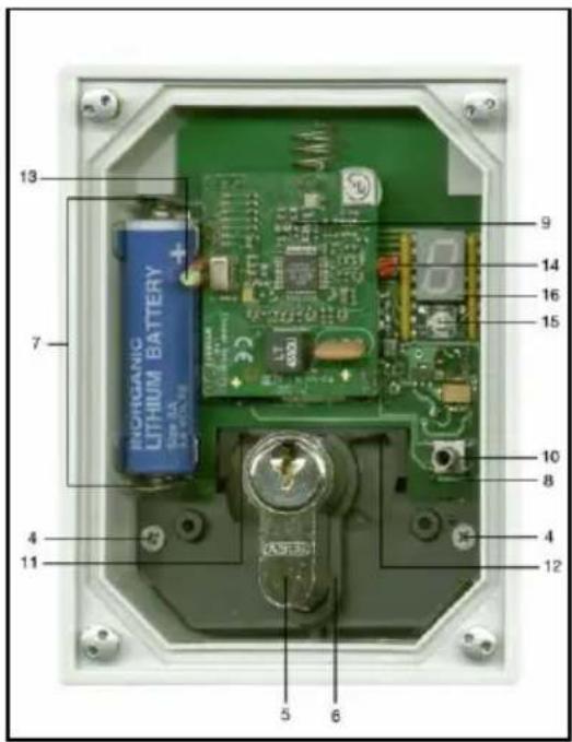
Fig. 2 Housing open, with PCB
1 Opening for wall mounting
2 Cable inlet
3 PCB holder
4 Fixing screws for PCB
5 Half cylinder
6 Fixing screw
7 Battery holder
8 Terminal block for 12V connection (PCBs rear)
9 Wall sabotage switch (PCBs rear)
10 Cover sabotage switch
11 Left button
12 Right button
13 Left green LED
14 Right red LED
15 Programming button
16 7-segment LED display
7. Installation
- Unscrew the cover bolts with the Allen key provided and remove the housing cover.
- Remove the two fixing screws (4) to the left and right of the black moulded piece.
- Carefully lift the PCB out of the black moulded piece.
- Use the rear of the wireless key switch housing as a template and mark the drill holes (1). Drill the mounting holes.
- Only for permanent 12V power supply: guide the connection cable through the opening provided (2).
- Affix the housing to the wall.
- Install the half cylinder (5): insert a key into the half cylinder (5) and turn the locking nose using the key until the half cylinder (5) can be slid into the bracket. Now affix the half cylinder (5) using the fixing screw (6). Then check whether both buttons can be activated using the locking nose.
- Only for permanent 12V power supply: connect the cable to the correct pole of the terminal block (8). The terminal block poles are labelled accordingly. Ensure that stripped sections of unused cable wire do not come into contact with the PCB.
- Re-insert the PCB, ensuring that the spring for the wall sabotage switch (9) is correctly positioned. Then screw in the two fixing screws (4) to the left and right of the black moulded piece.
- Insert the battery provided into the battery holder (7), ensuring the polarity is correct. If a permanent 12 V power supply is being used, you do not require a battery for the wireless key switch to function. When a 12 V supply voltage is detected, the battery is automatically disconnected. You can, however, use the battery as a back-up power source, as the wireless key switch automatically switches to battery operation mode if the 12 V power supply is interrupted.
- Now proceed with section 8. If you do not want to use the switch for all four partitions, and do not want to use the administrator code "1234", program the wireless key switch in accordance with sections 8.5 and 8.3. Follow section 8.6 to pair the wireless key switch with your Secvest wireless alarm panel. In operating mode 1, the Secvest wireless alarm panel is also operated using the wireless key switch. Also note the information in sections 8.2, 8.4 and 8.7.
- Place the parts of the core extraction protector on the cylinder.
- Ensure that the spring for the cover sabotage switch (10) is in the correct position, and that the O-ring is lying flush in the housing groove. Replace the housing cover and tighten the cover bolts.
- Now proceed with section 9.
8. Programming
The wireless key switch transmits a user code to your Secvest when operated. In operating modes 1 and 3, the wireless key switch also transmits the partition numbers. Once your wireless alarm panel has armed or disarmed itself, your Secvest will then send a message to the wireless key switch about its current status. This status is then displayed on the wireless key switch.
To enable the wireless key switch to fulfil these functions, please proceed as follows:
- Program the operating mode
- Program the acoustic signals
- Program the user code
- Program the reception time
- Program the partition (for operating mode 1 and 3)
- Pair the wireless key switch with your Secvest
- Pair the Secvest with the wireless key switch (only for operating mode 1)
Press the programming button (15) to call up the programming menu. The programming menu consists of six sub-menus:
- Operating mode Here you can select from
Operation as a wireless control panel (FU5140) and wireless info module (FU8200, FUMO50030)
Operation as a 2WAY wireless control panel (FU8110)
Operation as a wireless control panel (FUBE50001 with rolling code), factory setting see section 8.1.
- Beep tones Here, you can switch the signal tones of the wireless key switch on and off see section 8.2.
- User code Here, you can program the user code see section 8.3.
4.8 Time Here, you can change the reception time of the wireless key switch see section 8.4.
5.8 Partitions Here, you can determine the partitions to which the wireless key switch is assigned and for which user authorisation is available in operating mode 1 and 3 see section 8.5.
6.8 Pairing mode Here, you can pair your wireless alarm panel with the wireless key switch. This allows the key switch to display whether your wireless alarm panel is armed or disarmed only in operating mode 1 see section 8.6.2.
You can access the required sub-menu by repeatedly pressing the programming button (15).
The programming menu will be exited at all menu tiers after approx.
2 seconds if the programming button (15) is not pressed.
Each of the sub-menus as well as pairing mode can be enabled by holding in the programming button (15). The symbol E will then appear for confirmation.

Note
Factory settings of the wireless key switch:
- User code is set as "1234"
All 4 partitions are selected - Beep tones are activated
- Reception time is set to 10 s
8.1. Operating mode of the wireless key switch
Press the programming button (15) once to access this sub-menu. I will appear on the display. Hold down the button until it appears on the display.
After approx. 1 s, the current setting will be displayed (e.g.). This
number can then be changed by repeatedly pressing the button. When is displayed, the operating mode
"operation as a wireless control panel (FU5140) and wireless info module (FU8200, FUMO50030)" is enabled.
8 indicates the operating mode "Operation as a 2WAY wireless control panel (FU8110)"
8 indicates the operating mode "Operation as a wireless control panel (FUBE50001 with rolling code)"
When you have reached the desired number, hold down the button until appears on the display to confirm.

Note
Operating mode

"operation as a wireless control panel (FU5140) and wireless info module (FU8200, FUMO50030)" is enabled.
Compatible with Secvest FU500X and Secvest 2WAY FU800X
Operating mode 2
Operation as a 2WAY wireless control panel (FU8110)
Compatible with Secvest 2WAY FU800X and Secvest FUAA50XYZ
Operating mode 3
Operation as a wireless control panel (FUBE50001 with rolling code)
Compatible with Secvest FUAA50XYZ S/W >= V2.00.06
8.2. Switching the beep tones on and off
Press the programming button (15) twice to access this sub-menu. will appear on the display. Hold down the button until appears on the display.
During programming, will appear on the display when the beep tones are switched on or off, and after approx. 1 second the current setting will be displayed (e.g.). This number can then be changed by repeatedly pressing the button. When is displayed, the beep tones are enabled.
When L is displayed, the beep tones on the wireless key switch are disabled.
When you have reached the desired number, hold down the button until appears on the display to confirm.
8.3. User code for the wireless key switch
Press the programming button (15) three times. will appear on the display. Hold down the button until appears on the display.
When setting the user code, the display will show to indicate that the first digit is being set, and after approx. 1 second the current setting will be
displayed (e.g.). This number can then be changed by pressing the button. Each of the 4 or 6 digits in the user code can be numbers between
0 and 9 (Uic3). The fifth and sixth digits can also
be set to the value
When you have reached the desired value, hold down the button until 8 appears on the display to confirm. When you release the button, the display indicates that the second digit is being set by showing 2 and you can proceed as before.
When setting the third digit, 3 appears, when setting the fourth digit appears, the fifth digit and the sixth digit Program all six digits of the user code in this way.

Note
Only the Secvest FUAA50XYZ supports a six-digit user code. If you are using a four-digit user code, set the fifth and sixth digits to
If you have not yet done so, please register a new user with your Secvest. You can find instructions for doing so in your Secvest user guide.
Please observe the information on handling log-in details for your security systems. This can be found in the user manual and the instructions for installers for the Secvest FUA50XYZ, under the section "Security information".
8.4. Reception time
This menu item allows you to freely select the reception time of the wireless key switch.

Note
A shorter reception time preserves the battery life of the device.
Press the programming button (15) four times. will appear on the display. Hold down the button until appears on the display.
After approx. 1 s, the current setting will be displayed (e.g.). This setting can then be changed by repeatedly pressing the programming button (15). The possible values are:
018396
When you have reached the desired value, hold down the programming
button until appears on the display. This confirms that the setting has been changed.
Programming values:
| Programming value | Reception time |
| 0 | 5 seconds |
| 1 | 10 seconds |
| 2 | 20 seconds |
| 3 | 30 seconds |
| 4 | 45 seconds |
| 5 | 60 seconds |
| 6 | 120 seconds |

Note
Under the factory settings, the exit delay for the panel is 10 seconds. If the exit delay of the panel has been changed, you must also adjust this time setting for the wireless key switch.
The exit delay time of panels can be viewed in installer mode under the menu item "Partitions".
When the exit mode of the Secvest is set to "Instant", the reception time of the wireless key switch should be set to 5 seconds.
8.5. Partition of the wireless key switch
To access this sub-menu, press the programming button (15) five times.
will appear on the display. Hold down the button until it appears on the display.
When programming the first partition, the display will show to indicate that the first partition is being set, and after approx. 1 second the current setting will be displayed (e.g.). This number can then be changed by pressing the button. When is displayed, a partition has been selected. indicates a partition that has not been selected.
When you have reached the desired value, hold down the button until 0 appears on the display to confirm. When you release the button, the display shows 2 to indicate that the second partition is being set, and the procedure can be repeated.
The third partition is indicated by 3 and the fourth by 8. Program all four partitions in this way.

Note
Be sure to set the partition for which the user or user code has authorisation to "Selected"().
Partitions can be assigned to the relevant user via the user menu of your Secvest wireless alarm panel under the menu item:
Users Edit User Partition

Note
Please note that if you wish to select several partitions, these partitions should be assigned the same types and delay times when programming your Secvest wireless alarm panel.
We recommend using only one partition. This also ensures that the status feedback from the panel remains clear.
8.6. Pairing and deleting the wireless key switch
The wireless key switch is taught in to the wireless alarm panel in the same way as a normal wireless control panel.
Only in operating mode 1
In addition, the operating steps for pairing a wireless alarm panel with an info module should also be carried out.
8.6.1. Pairing the wireless key switch with the Secvest wireless alarm panel and deleting it
- In installer mode, select the menu item " (Other) components Wireless control panel Add/delete wireless control panel", and select a wireless control panel. Transmit the pairing signal from the wireless key switch to the wireless alarm panel by pressing a sabotage switch multiple times.
- Once the pairing signal has been picked up by the wireless alarm panel, it will emit two beeps and the symbol will appear behind the selected wireless control panel.
- Exit this menu item.

Note
To delete the wireless key switch, go to installer mode and select the menu item " (Other) components Wireless control panel Add/delete wireless control panel". Select the corresponding wireless control panel and deleted it by following the instructions on the display.
8.6.2. Assigning the Secvest to the wireless switch key and deleting it
Only in operating mode 1
- Put the wireless key switch into pairing mode.
- Press the programming button (15) six times. will appear on the display. Hold down the button until appears on the display.
- After letting go of the button, will briefly appear on the display.
- Pairing mode is now activated. A new Secvest can now be taught in within the next four minutes.
- In installer mode, select the menu item " (Other) components Info module Program info module (add panel)". Transmit the pairing signal from the wireless alarm panel to the wireless key switch.
- Once the pairing signal has been received by the wireless key switch, it will emit a double beep.
- Confirm the successfully completed pairing process on the Secvest wireless alarm panel.

Note
If you are pairing a new Secvest wireless alarm panel with the wireless key switch, previous pairing data on the wireless alarm panel are automatically deleted.
8.7. Button assignment of wireless control panel for controlling wireless alarm panel
8.7.1. Operating mode
The left button (11) of the wireless key switch is used for arming, and always transmits the code "Button 1". This button corresponds to button 1 in the Secvest installer mode menu "Other components Wireless control panel Edit wireless control panel".
The right button (12) of the wireless key switch is used for disarming, and always transmits the code "Button 4". This button corresponds to button 4 in the Secvest installer mode menu "Other components Wireless control panel Edit wireless control panel".
By default, the buttons of a wireless control panel for use with a Secvest FU500X wireless alarm panel (software version 2.xx.yy and 3.xx.yy) are assigned as follows (factory settings):
Button 1: Arm all
Button 4: Disarm all
For arming and disarming the Secvest FU500x wireless alarm panel (software version 2.xx.yy and 3.xx.yy), you do not need to make any changes under this menu item of the wireless alarm panel.

Note
If you wish to use the wireless key switch to internally arm a partition or switch outputs, go to the installer menu of the wireless alarm panel and select "Other components Wireless control panel Edit wireless control panel", and select the relevant wireless control panel. Now you can reassign buttons 1 and 4. The following options are available in
software version 2.xx.yy and upwards:
Arm all
Internal arming
- Disarm all
Output z (on or off)
In software version 3.xx.yy and upwards:
Arm all
Internal arming
- Disarm all
Output z (on, off, switch or pulse)
The button codes transmitted by the wireless key switch are not freely programmable.
Now continue with installation from point 12 of section 7.
8.7.2. Operating mode
The left button (11) of the wireless key switch is used for arming, and always transmits the code "Button 1". This button corresponds to button 1 (button A) in the Secvest installer mode menu "Other components Wireless control panel Edit wireless control panel".
The right button (12) of the wireless key switch is used for disarming, and always transmits the code "Button 4". This button corresponds to button 4 (button D) in the Secvest installer mode menu "Other components Wireless control panel Edit wireless control panel".
The Secvest 2WAY FU800X and Secvest FUAA50XYZ wireless alarm panels have different factory settings for the button assignment of wireless control panels. The buttons are assigned according to the labels on the control panel (FU8110).
By default, the buttons of a wireless control panel for use with a Secvest 2WAY FU800X (software version 5.xx.yy) or Secvest FUAA50XYZ wireless alarm panel are assigned as follows (factory settings):
Button 1: Arm all
Button 4: Not used

Note
If you are using this wireless key switch with the Secvest 2WAYFU800x (software version 5.xx.yy) or with the Secvest FUAA50XYZ, you must reset button 4 to "Disarm all".

Note
If you wish to use the wireless key switch to internally arm a partition or switch outputs, go to the installer menu of the wireless alarm panel and select "Other components Wireless control panel Edit wireless control panel", and select the relevant wireless control panel. Now you can reassign buttons 1 and 4. The following options are available:
Arm all
Internal arming
Disarm all
Output z (on, off, switch or pulse)
The button codes transmitted by the wireless key switch are not freely programmable.
Now continue with installation from point 12 of section 7.
8.7.3. Operating mode 3
The left button (11) of the wireless key switch is used for arming, and always transmits the code "Button A".
The right button (12) of the wireless key switch is used for disarming, and always transmits the code "Button B".

Note
The setting for button C under the Secvest installer mode menu item "Components Wireless control panel Edit wireless control panel" does not affect the functionality of the wireless key switch in operating mode 3.
The button codes transmitted by the wireless key switch are not freely programmable.
Now continue with installation from point 12 of section 7.
9. Operation
Arming
To arm your Secvest wireless alarm panel, turn the key to the right as far as it will go. This causes the locking nose to press the left button (11).
The red LED on the right (14) will flash briefly, indicating that the wireless key switch has transmitted the information to the panel and there is sufficient battery capacity available. If the LED does not light up during battery operation, check the charge status of the batteries.
Once the exit delay period has passed, the wireless alarm panel is armed and transmits information about its armed status to the wireless key switch. The wireless key switch indicates this by causing the red LED on the right (14) to flash for around 6 seconds. The wireless key switch will beep twice.
Disarming
To disarm your Secvest wireless alarm panel, turn the key to the left as far as it will go. This causes the locking nose to press the right button (12).
The green LED on the left (13) will flash briefly, indicating that the wireless key switch has transmitted the information to the panel and there is sufficient battery capacity available. If the LED does not light up during battery operation, check the charge status of the batteries.
The wireless alarm panel is now disarmed and transmits information about its disarmed status to the wireless key switch. The wireless key switch indicates this by causing the green LED on the left (13) to flash for around 6 seconds. The wireless key switch will beep once.

Note
The wireless key switch will beep eight times if it is unable to receive status information from the wireless alarm panel.
10. Maintenance
Put your Secvest wireless alarm panel into installer mode. You can now open the wireless key switch without a sabotage alarm being triggered. Replace the battery with another battery of the same type.
In the case of an external power supply being used, please remember to replace the batteries before their expiry date.
If the batteries need to be replaced, the alarm control panel will display the error message "FKBDT == batt low". In this case, the batteries should be replaced by an installer.
The internal buttons must undergo functional testing every year, and the key switch must also be cleaned.
With FUA50XYZ
In order to launch functional testing of the internal buttons, ensure that the system is not currently in operation. In installer mode, select "Test wireless control panel wireless control panel 01-08".
Select the wireless control panel required. The display now shows "Press key to test". Turn the key to the right (arm) or to the left (disarm).
The display now shows the programmed user code followed by the internal button that was pressed, e.g. "1234A" or "1234B".
Clean the outside of the housing. Do not use any form of solvent or cleaning agent.
11. Technical data
| Power supply | 3.6 V DC (AA Li battery, FU2992) or 12 V DC |
| “Low battery” error message | < 2.8 V (“low battery” threshold) |
| Dimensions | 87 x 117 x 47 mm (WxHxD) |
| Protection class | IP55 |
| Weight | 546 g |
| Operating temperature | -10°C to +55°C |
| Frequency, wireless | 868.6625 MHz |
| Transmission power, wireless | max. 10 mW |
| Displays | 2 status LEDs, red and green |
| Signals | Integrated piezo sounder |
| Access code | 4-digit or 6-digit |
| EU Directives | RED: 2014/53/EU, EMC: 2014/30/EU, RoHS: 2011/65/EU WEEE: 2012/19/EU, ErP: 2009/125/EC, Low Voltage: 2014/35/EU, General Safety: 2001/95/EC |
| Power consumption | Battery operation | 12 V DC operation |
| Stand-by | 4 μA | 15 mA |
| Programming | 36 mA | 90 mA |
| Transmission | 33 mA | 90 mA |
The manufacturer reserves the right to make technical modifications without prior notice.
12. Warranty
-
ABUS products are designed and manufactured with the greatest care and tested according to the applicable regulations.
-
The warranty only covers defects caused by material or manufacturing errors at the time of sale. If there are demonstrable material or manufacturing errors, the product will be repaired or replaced at the guarantor's discretion.
-
In such cases, the warranty ends when the original warranty period of two years expires. All further claims are expressly rejected.
-
The warranty does not cover the batteries supplied.
-
ABUS will not be held liable for defects and damage caused by external influences (e.g. transport, use of force, operating errors), inappropriate use, normal wear and tear or failure to observe the instructions in this manual.
-
In the event of a warranty claim, the original receipt with the date of purchase and a short written description of the problem must be supplied with the product.
-
If within the first two years following purchase you discover a defect on your product which existed at the time of purchase, contact your dealer directly.
13. Disposal

Dispose of the device in accordance with EU Directive 2012/19/EU – WEEE (Waste from Electrical and Electronic Equipment). If you have any questions, please contact the municipal authority responsible for disposal. You can get information on collection points for waste equipment from your local authority, from local waste disposal companies or your dealer, for example.
14. Declaration of conformity
ABUS Security-Center GmbH & Co. KG hereby declares that this type of wireless system, item number FUBE50061, complies with Directive 2014/53/EU. The full EU Declaration of Conformity text can be found at www.abus.com, Item search FUBE50061/Downloads.
The Declaration of Conformity can also be obtained from the following address:
Chere cliente, cher client,
FUAA50XYZ softwareversions <=2.00.00
FU800X
FU500X
Si los trabajo de instalación no se realizan de manière adecuada, ellos peuvent provocar falsas interpretaciones de las señales. Las consecuenciasSEOSEOSEOSEOSEOSEOSEOSEOSEOSEOSEOSEOSEOSEOSEOSEOSEOSEOSEOSEOSEOSEOSEOSEOSEOSEOSEOSEOSEOSEOSEOSEOSEOSEOSEOSEOSEOSEOSEOSEOSEOSEOSEOSEOSEOSEOSEOSEOSEOSEOSEOSEOSEOSEOSEOSEOSEOSEOSEOSEOSEOSEOSEOSEOSEOSEOSEOSEOSEOSEOSEOSEOSEOSEOSEOSEOSEOSEOSEOSEOSEOSEOSEOSEOSEOSEOSEOSEOSEOSEOSEOSEOSEOSEOSEOSEOSEOSEOSEOSEO SEOEO SEOEO SEOEO SEOEO SEOEO SEOEO SEOEO SEOEO SEOEO SEOEO SEOEO SEOEO SEOEO SEOEO SEOEO SEOEO SEOEO SEOEO SEOEO SEOEO SEOEO SEOEO SEOEO SEOEO SEOEO SEOEO SEOEO SEOEO SEOEO SEOEO SEOEO SEOEO SEOEO SEOEO SEOEO SEOEO SEOEO SEOEO SEOEO SEOEO SEOEO SEOEO SEOEO SEOEO SEOEO SEOEO SEOEO SEOEO SEOEO SEOEO SEOEQ
- Preface
- PEACE OF MIND AND SECURITY THANKS TO ROLLING CODE
- Note
- Limitation of liability
- Intended use
- Contents
- Safety information
- Danger
- Battery warning information
- Important
- Use of user codes
- Installation and operation
- Packaging
- Main features
- Scope of delivery
- Description and connections
- Installation
- Programming
- Operating mode of the wireless key switch
- Operating mode
- Operating mode 2
- Operating mode 3
- Switching the beep tones on and off
- User code for the wireless key switch
- Reception time
- Programming values:
- Partition of the wireless key switch
- Pairing and deleting the wireless key switch
- Only in operating mode 1
- Pairing the wireless key switch with the Secvest wireless alarm panel and deleting it
- Assigning the Secvest to the wireless switch key and deleting it
- Button assignment of wireless control panel for controlling wireless alarm panel
- Operating mode
- Operating mode
- Operating mode 3
- Operation
- Arming
- Disarming
- Maintenance
- With FUA50XYZ
- Technical data
- Warranty
- Disposal
- Declaration of conformity
Brand : ABUS
Model : FUBE50061
Category : Electrical switch