
Dolceclima Air Pro 14 - Air Conditioning OLIMPIA SPLENDID - Free user manual and instructions
Find the device manual for free Dolceclima Air Pro 14 OLIMPIA SPLENDID in PDF.
| Product type | Monoblock portable air conditioner |
| Brand | Olimpia Splendid |
| Model | Dolceclima Air Pro 14 |
| Dimensions (W x H x D) | 490 x 765 x 425 mm |
| Weight | Approximately 30 kg |
| Power supply | 220-240 V ~ 50 Hz |
| Power consumption (cooling) | Approximately 1.5 kW |
| Refrigerant gas | R290 (flammable) |
| Operating modes | Cooling, heating (heat pump), dehumidification, ventilation, turbo, automatic |
| Special functions | Silent, sleep, Follow Me, timer, Wi-Fi, auto restart |
| Temperature range (cooling) | 17 °C to 35 °C (62 °F to 95 °F) |
| Temperature range (heating) | 5 °C to 30 °C (41 °F to 86 °F) |
| Temperature range (dehumidification) | 13 °C to 35 °C (55 °F to 95 °F) |
| Air flow | Not specified (estimated: 200-300 m³/h) |
| Noise level | Not specified (estimated: 45-55 dB(A)) |
| Recommended area | Up to 30 m² (estimated) |
| Filter maintenance | Clean every two weeks; replace additional filters after 500 hours |
| Condensate drainage | Manual drainage or continuous via hose depending on mode |
| Safety | Thermal protection, auto shutdown on full tank, refrigerant leak detection |
| Warranty | 2 years (standard per EU legislation) |
| Repairability | Use only original Olimpia Splendid spare parts; intervention by authorized service center |
Frequently Asked Questions - Dolceclima Air Pro 14 OLIMPIA SPLENDID
User questions about Dolceclima Air Pro 14 OLIMPIA SPLENDID
0 question about this device. Answer the ones you know or ask your own.
Ask a new question about this device
Download the instructions for your Air Conditioning in PDF format for free! Find your manual Dolceclima Air Pro 14 - OLIMPIA SPLENDID and take your electronic device back in hand. On this page are published all the documents necessary for the use of your device. Dolceclima Air Pro 14 by OLIMPIA SPLENDID.
USER MANUAL Dolceclima Air Pro 14 OLIMPIA SPLENDID
natural_image
Line drawing of a portable electronic device with a lid and front panel (no text or symbols)DOLCECLIMA AIR PRO
Caution: risk of fire
natural_image
Illustration of a kitchen setup with an oven and two appliances crossed out by a diagonal line (no text or symbols)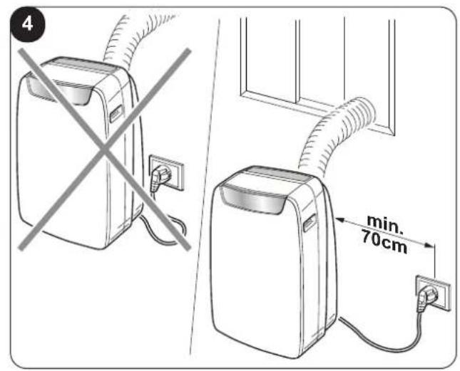
natural_image
Diagram showing two identical devices with a diagonal line crossing, no text or symbols present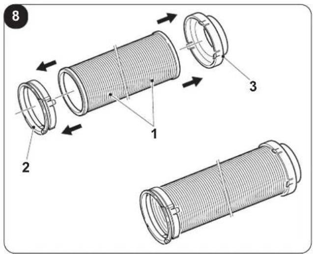
natural_image
Line drawing of a remote control casing with an arrow indicating left motion (no text or symbols)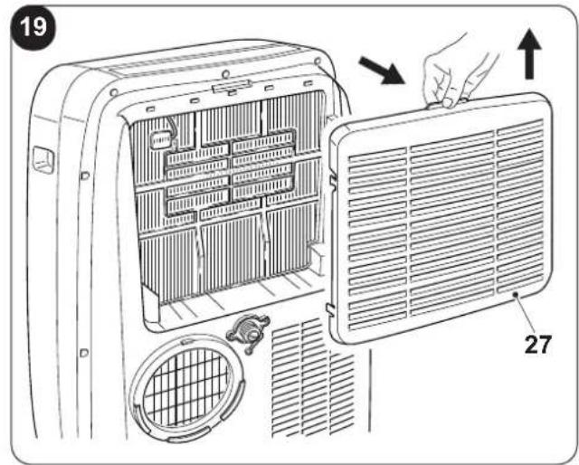
natural_image
Diagram showing a vehicle roof with diagonal cross lines indicating no change or restriction (no text or symbols present)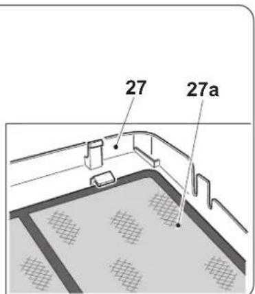


natural_image
Diagram of a car air conditioner unit with attached cable and connector, showing internal components and wiring (no text or labels)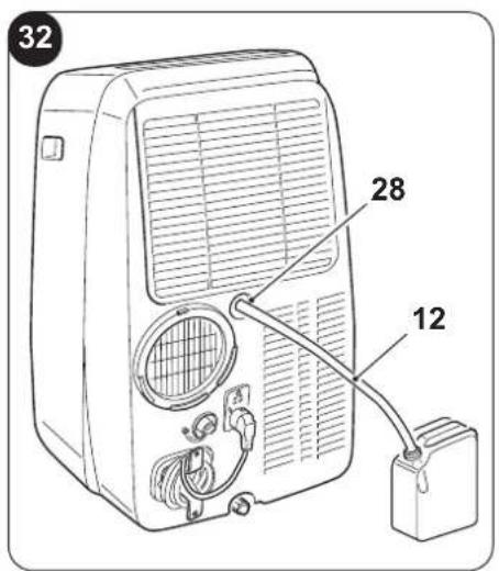
natural_image
Line drawing of an air conditioner unit with a diagonal line crossing the door (no text or symbols)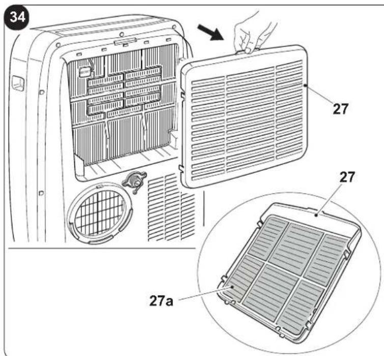
natural_image
Technical line drawing of a vehicle front panel with internal compartments and ventilation slots (no text or symbols)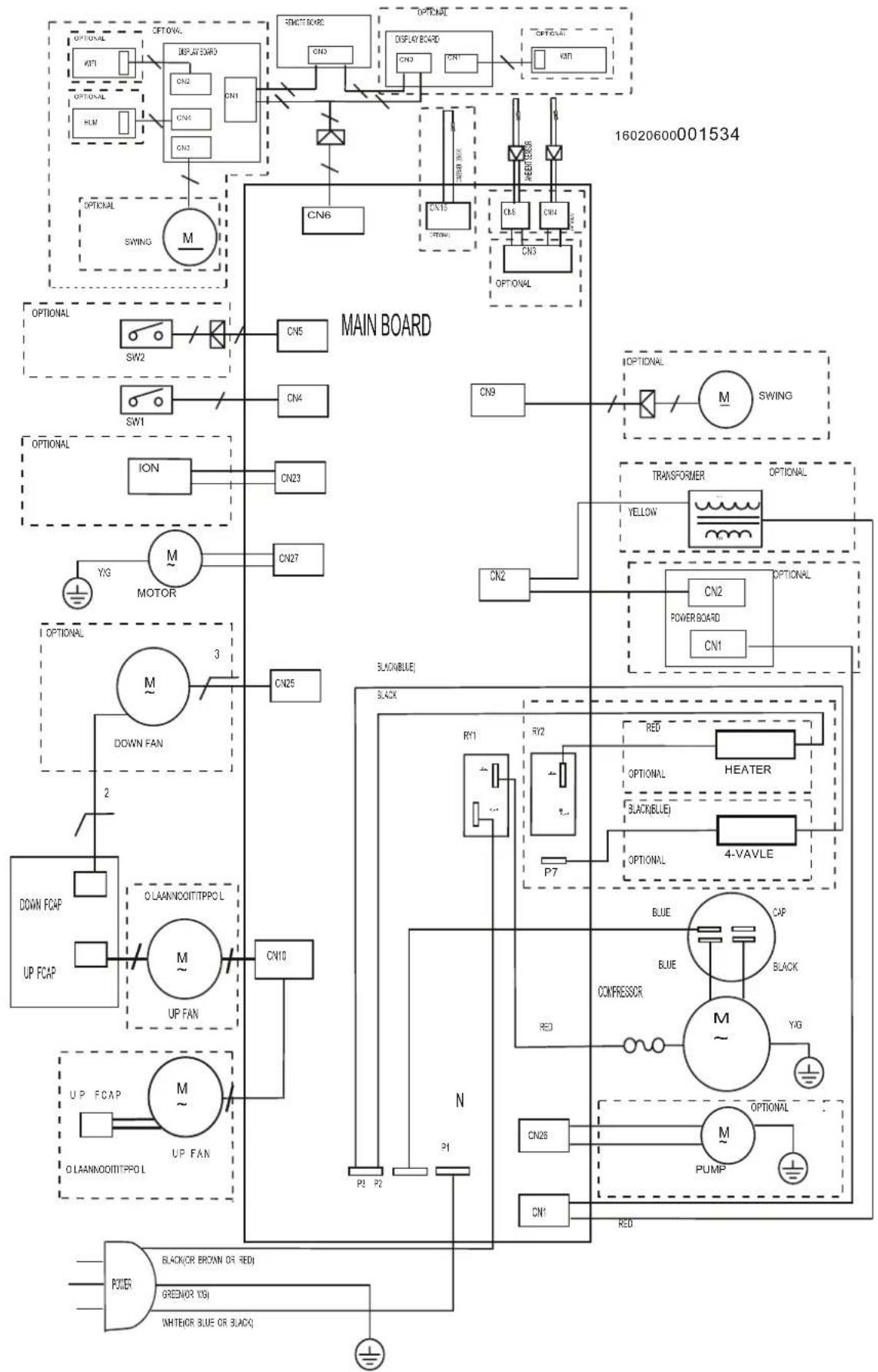
flowchart
graph TD
    subgraph MAIN BOARD
        direction TB
        A["MAIN BOARD"] --> B["SW1"]
        A --> C["SW2"]
        A --> D["ION"]
        A --> E["MOTOR"]
        A --> F["DOWN FAN"]
        A --> G["DOWN FOAP"]
        A --> H["UP FOAP"]
        A --> I["UP FAN"]
        A --> J["UP FAN"]
        A --> K["BLACKBLUE"]
        A --> L["RY1"]
        A --> M["RY2"]
        A --> N["P7"]
        A --> O["HEATER"]
        A --> P["COMPRESSOR"]
        A --> Q["POWER BOARD"]
        A --> R["POWER"]
    end

    subgraph AUX EQUIPMENT BOARD
        direction TB
        S["MAIN BOARD"] --> T["SW1"]
        S --> U["SW2"]
        S --> V["ION"]
        S --> W["MOTOR"]
        S --> X["DOWN FAN"]
        S --> Y["DOWN FOAP"]
        S --> Z["UP FOAP"]
        S --> AA["UP FAN"]
        S --> AB["UP FAN"]
        S --> AC["BLACKBLUE"]
        S --> AD["RY1"]
        S --> AE["RY2"]
        S --> AF["P7"]
        S --> AG["HEATER"]
        S --> AH["COMPRESSOR"]
        S --> AI["RY1"]
        S --> AJ["RY2"]
        S --> AK["P7"]
        S --> AL["HEATER"]
        S --> AM["PUMP"]
    end

    subgraph POWER BOARD
        direction TB
        AN["POWER"] --> AO["BLACKCR BROWN OR REDI"]
        AN --> AP["GREENCR YES"]
        AN --> AQ["WHITEOR BLUE OR BLACKQ"]

    end

    style MAIN BOARD fill:#f9f,stroke:#333
    style AUX EQUIPMENT BOARD fill:#ccf,stroke:#333
0 - AVVERTENZE 2
0.1 - INFORMAZIONI GENERALI 2
0.2 - SIMBOLOGIA 2
0.2.1 - Pittogrammi redazionali....2
0.3 - AVVERTENZE GENERALI 3
0.4 - USO PREVISTO 5
0.5 - ZONE DI RISCHIO....6
0.6 - AVVERTENZE PER IL GAS
REFRIGERANTE R290....6
1 - DESCRIZIONE APPARECCHIO....11
1.1 - ELENCO COMPONENTI FORNITI
A CORREDO....11
natural_image
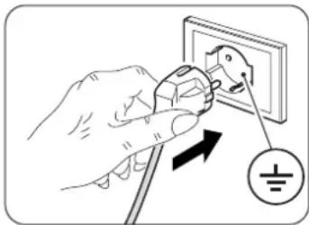
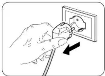
Illustration of a hand using a power plug to switch an electrical outlet (no text or symbols present)
AVVERTENZA
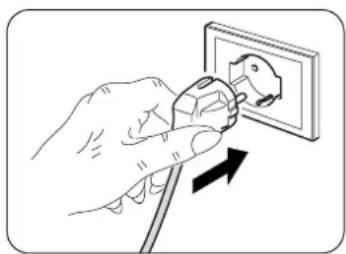
natural_image
Illustration of a hand using a power plug to switch an electrical outlet (no text or symbols present)
0 - WARNINGS ......2
0.1 - GENERAL INFORMATION ......2
0.2 - SYMBOLS 2
0.2.1 - Editorial pictograms....2
0.3 - GENERAL WARNINGS....3
0.4 - PROPER USE 5
0.5 - HAZARDOUS ZONES 6
0.6 - WARNINGS FOR R290
REFRIGERANT GAS....6
1 - DESCRIPTION OF THE APPLIANCE .....11
1.1 - LIST OF THE COMPONENTS SUPPLIED .. 11
1.2 - IDENTIFICATION OF THE MAIN COMPONENTS....11
2 - INSTALLATION ....12
2.1 - HOW TO TRANSPORT
THE CONDITIONER....12
2.2 - WARNINGS....12
2.3 - MOBILE INSTALLATION....12
2.4 - FIXED INSTALLATION....13
2.5 - ELECTRICAL CONNECTION .....13
2.6 - DRAINAGE....13
2.6.a - Use as dehumidifier....13
2.6.b - Use as heat pump
(only for the suitable version)....13
3 - USE OF THE APPLIANCE ....14
3.1 - CONTROL PANEL SYMBOLS AND KEYS ..14
3.2 - REMOTE CONTROL KEYS (Fig. C)......15
3.3 - USE OF THE REMOTE CONTROL .....16
3.3.a - Insertion of batteries....16
3.3.b - Replacement of batteries .....16
3.3.c - Location of the remote control....16
3.4 - USE OF THE APPLIANCE....17
3.4.a - Preliminary operations....17
3.4.b - Appliance switching on/off....17
3.5 - AUTO MODE (Automatic) 17
3.6 - COOLING MODE (COOL) .....17
3.7 - TURBO COOLING MODE .....18
3.8 - DEHUMIDIFICATION MODE (DRY) .....18
3.9 - VENTILATION MODE (FAN)....18
3.10 - HEATING MODE (HEAT)
(only for version with heat pump) .....18
3.11 - TIMER MODE ....18
3.11.a Programmed switching on....19
3.11.b - Programmed switching off .....19
3.12 - OTHER FUNCTIONS....19
3.12.a - SILENT function....19
3.12.b - SLEEP function ..... 19
3.12.c - FOLLOW ME function .....20
3.12.d - Setting the unit of measurement of temperature 20
3.12.e - Directing the air flow 20
3.12.f - Short Cut function....20
3.12.g - Auto-Restart....20
3.12.h - Wi-Fi 20
4 - MAINTENANCE AND CLEANING .....21
4.1 - CLEANING 21
4.1.a - Cleaning the appliance and the remote control ..21
4.1.b - Air filters maintenance....21
4.1.c - Cleaning the air filter 21
4.1.d - Cleaning the suction filter 22
4.1.e - RECOMMENDATIONS FOR
ENERGY SAVING....22
4.2 - MAINTENANCE 22
4.2.a - Discharging condensation 22
4.2.b Error codes....23
5 - TECHNICAL DATA....23
6 - WIRING DIAGRAM ....23
7 - INCONVENIENCES AND POSSIBLE REMEDIES....24
0 - WARNINGS
0.1 - GENERAL INFORMATION
First of all, we would like to thank you for choosing our appliance.
0.2 - SYMBOLS
The pictograms in the next chapter provide the necessary information for correct, safe use of the machine in a rapid, unmistakable way.
0.2.1 - Editorial pictograms
 | Indicates that this document must be read carefully before installing and/or using the appliance. |
| Indicates that this document must be read carefully before any maintenance and/or cleaning operation. | |
 | Indicates that there may be additional information in attached manuals. |
| Indicates that information is available in the user manual or in the installation manual. | |
 | Indicates that the assistance personnel must handle the appliance following the installation manual. |
 | Indicates that the appliance uses inflammable refrigerant. If the refrigerant escapes and is exposed to a source of external ignition, there is a fire risk. |
 | Signals to the personnel that the operation described could cause electrocution if not performed according to the safety rules. |
 | It informs the personnel concerned that if the operation is not carried out in compliance with the safety regulations, it presents the risk of suffering physical damage. |
 | It informs the personnel concerned that if the operation is not carried out in compliance with the safety regulations, it presents the risk of burns due to contact with components at very high temperatures. |
 | Paragraphs marked with this symbol contain very important information and recommendations, particularly as regards safety. Failure to comply with them may result in:- danger of injury to the operators- loss of the warranty- refusal of liability by the manufacturer. |
| [C42X] | Refers to actions that absolutely must not be performed. |
| [840Y] | Indicates to the personnel concerned, that it is prohibited to cover the appliance, to prevent over-heating. |
0.3 - GENERAL WARNINGS
WHEN USING ELECTRICAL EQUIPMENT, BASIC SAFETY PRECAUTIONS MUST ALWAYS BE FOLLOWED IN ORDER TO REDUCE RISKS OF FIRE, ELECTRIC SHOCKS AND INJURY, INCLUDING THE FOLLOWING:

To prevent possible damages to the compressor, each start is delayed by 3 minutes with respect to the last switching off.

This document is restricted in use to the terms of the law and may not be copied or transferred to third parties without the express authorization of the manufacturer, OLIMPIA SPLENDID.
Our machines are subject to change and some parts may appear different from the ones shown here, without this affecting the text of the manual in any way.

Read this manual carefully before performing any operation (installation, maintenance, use) and follow the instructions contained in each chapter.

eep the manual carefully for future reference.

After removing the packaging, check that the appliance is in perfect condition. The packaging materials must not be left within reach of children as they can be dangerous.
-
THE MANUFACTURER IS NOT RESPONSIBLE FOR DAMAGES TO PERSONS OR PROPERTY CAUSED BY FAILURE TO FOLLOW THE INSTRUCTIONS IN THIS MANUAL.
-
The manufacturer reserves the right to make any changes it deems advisable to its models, although the essential features described in this manual remain the same.

The maintenance of equipment for conditioning such as this one may result dangerous since inside this appliance a refrigerant gas under pressure and live electrical components are present.
For this reason, possible maintenance interventions (with the exception of filters cleaning) must be performed exclusively by authorized and qualified personnel.
-
Failing to comply with the instructions contained in this manual, and using the unit with temperatures exceeding the permissible temperature range will invalidate the warranty.
-
Routine maintenance of the filters and general external cleaning can be done by the user as these operations are not difficult or dangerous.
-
During assembly and at each maintenance operation, it is necessary to respect the precautions indicated in this manual and on the labels located inside or on the appliance, as well as to take all the precautions suggested by common sense and by the Safety Regulations in force in the country of installation.
-
In case of replacement of parts, use only original OLIMPIA SPLENDID parts.

- If the unit is unused for a long period, or no-one uses the climate-controlled room, it is recommended to disconnect the electric power supply in order to prevent accidents.

- Do not use liquid or corrosive detergents to clean the unit, do not spray water or other liquids onto the unit, since they could damage the plastic components or even cause electric shocks.

- Do not wet the indoor unit and the remote control. Short circuits or fires may occur.

- In case of functioning anomalies (for example: abnormal noise, bad smell, smoke, abnormal increase in temperature, electrical dispersions, etc.), immediately switch off the appliance and disconnect the plug from the power socket.

For repair work contact solely the technical service centres authorised by the manufacturer and ask for original spare parts to be used. Failure to do this can affect the safety of the appliance.
- Do not let the air conditioner run for a long time when the humidity is very high and a door or a windows is left open.
Moisture may condense and wet or damage furniture.

-
Do not disconnect the power plug during functioning. or electrical shocks hazard.
-
Do not place heavy or hot objects on top of the appliance.
-
Before electrically connecting the appliance, make sure the plate data correspond to those of the distribution network. The power socket must be equipped with a Ground System. The plate (20) is located on the sides of the appliance (Fig.2).
-
Install the appliance according to the manufacturer's instructions. An incorrect installation can cause damage to people, animals or property for which the manufacturer accepts no responsibility.
-
If the appliance's plug is incompatible with the socket, have the socket replaced with a suitable one by a qualified technician, who must ascertain that the section of the socket cables is compatible with the power absorbed by the appliance. We do not recommend using adaptors and/or extension cables. If they cannot be avoided, however, they must comply with current safety regulations and their ampacity (A) must not be below the maximum ampacity of the appliance.
-
This appliance is not intended to be run via an external timer or with a separate remote control system.
-
Always and only use the appliance in a vertical position.
-
Do not obstruct the air inlet and outlet grids in any manner.
-
Do not insert extraneous items in the air inlet and outlet grids as this will create the risk of electrical shocks, fire or damages to the appliance.
-
Do not use the appliance:
- with wet or damp hands; - barefoot.
-
Do not pull the power cable or the appliance itself to remove the plug from the socket.
-
Do not use this product under direct sunlight or near a heat source such as a stove, heater or radiator (Fig.3).
-
Do not use the appliance near gas equipment (Fig.3).
-
Always place the appliance on a stable, plane and levelled surface.
-
Leave at least 30cm of free space on both sides and 20cm behind the appliance and leave at least 30cm of free space above it (Fig.1).
-
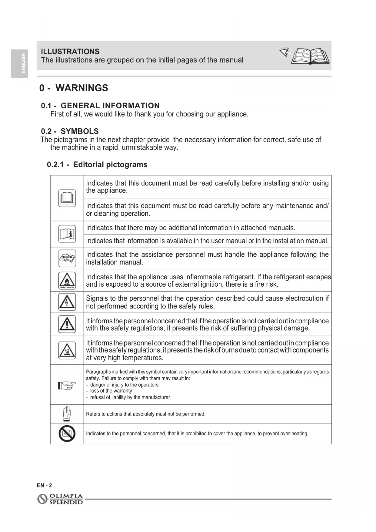
Do not place the appliance near a power socket (Fig.4).
-
The socket must be easily accessible so that the plug can be removed easily in an emergency.
-
Do not handle the plug with wet hands.
-
Do not excessively bend, twist, pull or damage the power cord.
-
Do not run the cord under carpeting, throw rugs or runners etc. Arrange cord away from traffic areas so that it will not be tripped over.
-
Unplug the cord when unit is not in use for an extended period of time and/or when no one is home.
-
Do not use the appliance in particularly moist environments (bathroom, kitchen, etc.).
-
Do not use the appliance outdoors or on wet surfaces. Avoid dropping liquids on the appliance. Do not use the appliance near sinks and taps.
-
Do not immerse the appliance in water or in other liquids.
EN - 4
-
Clean the appliance with a damp cloth; do not use abrasive products or materials. See the appropriate paragraph for the filters cleaning.
-
The most common cause of overheating is dust or lint deposit in the appliance. Regularly remove these accumulations by disconnecting the appliance from the power socket and vacuuming the grids.
-
Do not use the appliance in environments subject to significant temperature changes as condensation could form inside the appliance itself.
-
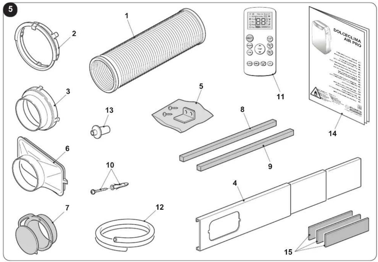
Install the appliance at at least 2 meters from other electronic devices (TV, radio, computer, dvd player, etc.) in order to avoid disturbances (Fig.6).
-
Do not use the appliance if insecticide gas has just been sprayed in the room or in the presence of burning incenses, chemical vapours or oily residues.
-
Do not use the appliance if the filters are not positioned correctly.
-
Disassembly, repair or reconversion performed by an unauthorized person could cause heavy damages and will cancel the manufacturer warranty.
-
Do not use the appliance in case of malfunctioning or faults, if the cord or plug are damaged, or if it has been dropped or damaged in any manner. Turn the appliance off, disconnect the plug from the socket and let it be checked by professionally qualified personnel.
-
Neither disassemble nor modify the appliance.
-
Repairing the appliance by yourself is extremely dangerous.
-
If you no longer wish to use this appliance, it must be made inoperative by cutting the power supply cable after removing the plug from the power socket. Hazardous parts of the appliance must be rendered harmless, especially as there is a risk of children playing with it.
-
Do not use tools different from those recommended by the manufacturer for the defrosting process and for the appliance cleaning.
-
The appliance is equipped with a thermal protector which preserves the circuit board in case of over-temperature. If this safety device intervenes, disconnect the plug from the power socket and wait for the appliance to completely cool down (at least 20÷30 minutes) and then reconnect the plug to the power socket and restart the appliance. If the appliance doesn't restart, disconnect the plug from the power socket and contact an Assistance Centre.
-
Transmission frequency: 2412-2472Mhz Maximum transmitted power: <20dBm
0.4 - PROPER USE
- The air conditioner must be used exclusively to produce warm* or cold air or to dehumidify air (upon choice) with the only purpose to make the environment temperature comfortable.
- This appliance is only intended for a domestic use or similar.
- An improper use of the appliance with possible damages caused to people, things or animals releases OLIMPIA SPLENDID from any responsibility.
0.5 - HAZARDOUS ZONES
- The climate controllers must not be installed in environments with the presence of inflammable gases, explosive gases, in very humid environments (laundries, greenhouses, etc.), or in places with other machines that generate a strong heat source, in proximity of a sources of salt water or sulphurous water.

DO NOT use gas, gasoline or other inflammable liquids near to the controller.
- Only use supplied components (see paragraph 1.1). The use of non-standard parts may cause water leaks, electric shocks, fires and injuries or damages to things.
This product must be used exclusively according to the specifications indicated in this manual. Use different to that specified, could cause serious injuries.
THE MANUFACTURER IS NOT LIABLE FOR INJURY/DAMAGE TO PERSONS/OBJECTS DERIVING FROM FAILURE TO COMPLY WITH THE REGULATIONS CONTAINED IN THIS MANUAL.
* Only for version with heat pump
0.6 - WARNINGS FOR R290 REFRIGERANT GAS
- THE APPLIANCE CONTAINS R290 GAS (FLAMMABILITY CLASSIFICATION A3).
- THE APPLIANCE SHALL BE STORED IN A WELL-VENTILATED AREA WHERE THE ROOM SIZE CORRESPONDS TO THE ROOM AREA AS SPECIFIED FOR OPERATION.
- THE APPLIANCE MUST BE INSTALLED, USED AND STORED IN A ROOM WITH A FLOOR SURFACE HIGHER THAN THE ONE INDICATED IN THE CHART.
| Quantity of R290 gas in Kg(see data label on the appliance) | 0,180 | 0,190 | 0,200 | 0,210 | 0,220 | 0,230 | 0,240 | 0,250 | 0,260 |
| Minimum size of the sitefor use and storage ( m^2 ) | 9 | 10 | 10 | 11 | 11 | 12 | 12 | 12 | 13 |
-
THIS APPLIANCE CONTAINS A QUANTITY OF REFRIGERANT GAS R290 EQUAL TO THE ONE INDICATED IN THE DATA LABEL LOCATED ON THE APPLIANCE.
-
THE APPLIANCE SHALL BE STORED IN A ROOM WITHOUT CONTINUOUSLY OPERATING IGNITION SOURCES (FOR EXAMPLE: OPEN FLAMES, AN OPERATING GAS APPLIANCE OR AN OPERATING ELECTRIC HEATER).
-
Do not pierce or burn.
-
Be aware that the refrigerants may not contain an odour.
-
R290 is a refrigerant gas in compliance with the European directives on environment. Do not pierce any part of the refrigerant circuit.
-
Do not use means to accelerate the defrosting process or to clean, other than those recommended by the manufacturer.
-
Do not use tools different from those recommended by the manufacturer when defrosting and cleaning the appliance.
-
If the appliance is installed, used or stored in a non-ventilated area, the room must be designed to prevent the accumulation of refrigerant leaks with the consequent fire or explosion hazard due to the refrigerant combustion caused by electrical heaters, stoves or others sources of ignition.
-
Compliance with national gas regulations shall be observed.
-
Keep ventilation openings clear of obstruction.
-
The appliance shall be stored so as to prevent mechanical damage from occurring.
EN - 6
- Any person who is involved with working on or breaking into a refrigerant circuit should hold a current valid certificate from an industry-accredited assessment authority, which authorises their competence to handle refrigerants safely in accordance with an industry recognised assessment specification.

Servicing shall only be performed as recommended by the equipment manufacturer.
Maintenance and repair requiring the assistance of other skilled personnel shall be carried out under the supervision of the person competent in the use of flammable refrigerants.
- TRANSPORT OF EQUIPMENT CONTAINING FLAMMABLE REFRIGERANTS
See transport regulations.
- MARKING OF EQUIPMENT USING SIGNS
See local regulations.
- DISPOSAL OF EQUIPMENT USING FLAMMABLE REFRIGERANTS
See national regulations.
- STORAGE OF EQUIPMENT/APPLIANCES
The storage of equipment should be in accordance with the manufacturer's instructions.
- STORAGE OF PACKED (UNSOLD) EQUIPMENT
Storage package protection should be constructed such that mechanical damage to the equipment inside the package will not cause a leak of the refrigerant charge.
The maximum number of pieces of equipment permitted to be stored together will be determined by local regulations.

- INFORMATION ON SERVICING
a) Checks to the area
Prior to beginning work on systems containing flammable refrigerants, safety checks are necessary to ensure that the risk of ignition is minimised.
For repair to the refrigerating system, the following precautions shall be complied with prior to conducting work on the system.
b) Work procedure
Work shall be undertaken under a controlled procedure so as to minimise the risk of a flammable gas or vapour being present while the work is being performed.
c) General work area
All maintenance staff and others working in the local area shall be instructed on the nature of work being carried out.
Work in confined spaces shall be avoided.
The area around the workspace shall be sectioned off.
Ensure that the conditions within the area have been made safe by control of flammable material.
d) Checking for presence of refrigerant
The area shall be checked with an appropriate refrigerant detector prior to and during work, to ensure the technician is aware of potentially flammable atmospheres.
Ensure that the leak detection equipment being used is suitable for use with flammable refrigerants, i.e. non-sparking, adequately sealed or intrinsically safe.
e) Presence of fire extinguisher
If any hot work is to be conducted on the refrigeration equipment or any associated parts, appropriate fire extinguishing equipment shall be available at hand.
Have a dry powder or CO2 fire extinguisher adjacent to the charging area.
f) No ignition sources
No person carrying out work in relation to a refrigeration system which involves exposing any pipe work that contains or has contained flammable refrigerant shall use any sources of ignition in such a manner that it may lead to the risk of fire or explosion.
All possible ignition sources, including cigarette smoking, should be kept sufficiently far away from the site of installation, repairing, removing and disposal, during which flammable refrigerant can possibly be released to the surrounding space.
Prior to work taking place, the area around the equipment is to be surveyed to make sure that there are no flammable hazards or ignition risks. No Smoking signs shall be displayed.
g) Ventilated area
Ensure that the area is in the open or that it is adequately ventilated before breaking into the system or conducting any hot work.
A degree of ventilation shall continue during the period that the work is carried out.
The ventilation should safely disperse any released refrigerant and preferably expel it externally into the atmosphere.
h) Checks to the refrigeration equipment
Where electrical components are being changed, they shall be fit for the purpose and to the correct specification.
At all times the manufacturer's maintenance and service guidelines shall be followed.
If in doubt consult the manufacturer's technical department for assistance.
The following checks shall be applied to installations using flammable refrigerants:
The charge size is in accordance with the room size within which the refrigerant containing parts are installed; The ventilation machinery and outlets are operating adequately and are not obstructed; If an indirect refrigerating circuit is being used, the secondary circuit shall be checked for the presence of refrigerant; Marking to the equipment continues to be visible and legible. Markings and signs that are illegible shall be corrected; Refrigeration pipe or components are installed in a position where they are unlikely to be exposed to any substance which may corrode refrigerant containing components, unless the components are constructed of materials which are inherently resistant to being corroded or are suitably protected against being so corroded.
i) Checks to electrical devices
Repair and maintenance to electrical components shall include initial safety checks and component inspection procedures. If a fault exists that could compromise safety, then no electrical supply shall be connected to the circuit until it is satisfactorily dealt with. If the fault cannot be corrected immediately but it is necessary to continue operation, an adequate temporary solution shall be used.
This shall be reported to the owner of the equipment so all parties are advised. Initial safety checks shall include: That capacitors are discharged: this shall be done in a safe manner to avoid possibility of sparking; That there no live electrical components and wiring are exposed while charging, recovering or purging the system; That there is continuity of earth bonding.
- REPAIRS TO SEALED COMPONENTS
a) During repairs to sealed components, all electrical supplies shall be disconnected from the equipment being worked upon prior to any removal of sealed covers, etc. If it is absolutely necessary to have an electrical supply to equipment during servicing, then a permanently operating form of leak detection shall be located at the most critical point to warn of a potentially hazardous situation.
b) Particular attention shall be paid to the following to ensure that by working on electrical components, the casing is not altered in such a way that the level of protection is affected.
This shall include damage to cables, excessive number of connections, terminals not made to original specification, damage to seals, incorrect fitting of glands, etc.
Ensure that apparatus is mounted securely.
Ensure that seals or sealing materials have not degraded such that they no longer serve the purpose of preventing the ingress of flammable atmospheres.
Replacement parts shall be in accordance with the manufacturer's specifications.

The use of silicon sealant may inhibit the effectiveness of some types of leak detection equipment. Intrinsically safe components do not have to be isolated prior to working on them.
- REPAIR TO INTRINSICALLY SAFE COMPONENTS
Do not apply any permanent inductive or capacitance loads to the circuit without ensuring that this will not exceed the permissible voltage and current permitted for the equipment in use. Intrinsically safe components are the only types that can be worked on while live in the presence of a flammable atmosphere.
The test apparatus shall be at the correct rating.
Replace components only with parts specified by the manufacturer.
Other parts may result in the ignition of refrigerant in the atmosphere from a leak.
- CABLING
Check that cabling will not be subject to wear, corrosion, excessive pressure, vibration, sharp edges or any other adverse environmental effects. The check shall also take into account the effects of aging or continual vibration from sources such as compressors or fans.
26. DETECTION OF FLAMMABLE REFRIGERANTS
Under no circumstances shall potential sources of ignition be used in the searching for or detection of refrigerant leaks.
A halide torch (or any other detector using a naked flame) shall not be used.
27. LEAK DETECTION METHODS
The following leak detection methods are deemed acceptable for systems containing flammable refrigerants.
Electronic leak detectors shall be used to detect flammable refrigerants, but the sensitivity may not be adequate, or may need re-calibration. (Detection equipment shall be calibrated in a refrigerant-free area).
Ensure that the detector is not a potential source of ignition and is suitable for the refrigerant used. Leak detection equipment shall be set at a percentage of the LFL of the refrigerant and shall be calibrated to the refrigerant employed and the appropriate percentage of gas (25 % maximum) is confirmed.
Leak detection fluids are suitable for use with most refrigerants but the use of detergents containing chlorine shall be avoided as the chlorine may react with the refrigerant and corrode the copper pipework.
If a leak is suspected, all naked flames shall be removed/ extinguished.
If a leakage of refrigerant is found which requires brazing, all of the refrigerant shall be recovered from the system, or isolated (by means of shut off valves) in a part of the system remote from the leak.
Oxygen free nitrogen (OFN) shall then be purged through the system both before and during the brazing process.
28. REMOVAL AND EVACUATION
When breaking into the refrigerant circuit to make repairs or for any other purpose conventional procedures shall be used.
However, it is important that best practice is followed since flammability is a consideration.
The following procedure shall be adhered to:
- Remove refrigerant;
• Purge the circuit with inert gas; - Evacuate;
• Purge again with inert gas; - Open the circuit by cutting or brazing.
The refrigerant charge shall be recovered into the correct recovery cylinders. The system shall be flushed with OFN to render the unit safe.
This process may need to be repeated several times.
Compressed air or oxygen shall not be used for this task.
Flushing shall be achieved by breaking the vacuum in the system with OFN and continuing to fill until the working pressure is achieved, then venting to atmosphere, and finally pulling down to a vacuum.
This process shall be repeated until no refrigerant is within the system. When the final OFN charge is used, the system shall be vented down to atmospheric pressure to enable work to take place.
This operation is absolutely vital if brazing operations on the pipe-work are to take place.
Ensure that the outlet for the vacuum pump is not close to any ignition sources and there is ventilation available.
29. CHARGING PROCEDURES
In addition to conventional charging procedures, the following requirements shall be followed.
Ensure that contamination of different refrigerants does not occur when using charging equipment.
Hoses or lines shall be as short as possible to minimise the amount of refrigerant contained in them.
Cylinders shall be kept upright.
Ensure that the refrigeration system is earthed prior to charging the system with refrigerant.
Label the system when charging is complete (if not already).
Extreme care shall be taken not to overfill the refrigeration system. Prior to recharging the system it shall be pressure tested with OFN.
The system shall be leak tested on completion of charging but prior to commissioning. A follow up leak test shall be carried out prior to leaving the site.
30. DECOMMISSIONING
Before carrying out this procedure, it is essential that the technician is completely familiar with the equipment and all its detail. It is recommended good practice that all refrigerants are recovered safely.
Prior to the task being carried out, an oil and refrigerant sample shall be taken in case analysis is required prior to re-use of reclaimed refrigerant. It is essential that electrical power is available before the task is commenced.
a) Become familiar with the equipment and its operation.
b) Isolate system electrically.
c) Before attempting the procedure ensure that:
- Mechanical handling equipment is available, if required, for handling refrigerant cylinders;
- All personal protective equipment is available and being used correctly;
• The recovery process is supervised at all times by a competent person; - Recovery equipment and cylinders conform to the appropriate standards.
d) Pump down refrigerant system, if possible.
e) If a vacuum is not possible, make a manifold so that refrigerant can be removed from various parts of the system.
f) Make sure that cylinder is situated on the scales before recovery takes place.
g) Start the recovery machine and operate in accordance with manufacturer's instructions.
h) Do not overfill cylinders. (No more than 80 % volume liquid charge).
i) Do not exceed the maximum working pressure of the cylinder, even temporarily.
j) When the cylinders have been filled correctly and the process completed, make sure that the cylinders and the equipment are removed from site promptly and all isolation valves on the equipment are closed off.
k) Recovered refrigerant shall not be charged into another refrigeration system unless it has been cleaned and checked.
31. LABELLING
Equipment shall be labelled stating that it has been de-commissioned and emptied of refrigerant.
The label shall be dated and signed.
Ensure that there are labels on the equipment stating the equipment contains flammable refrigerant.
32. RECOVERY
When removing refrigerant from a system, either for servicing or decommissioning, it is recommended good practice that all refrigerants are removed safely.
When transferring refrigerant into cylinders, ensure that only appropriate refrigerant recovery cylinders are employed.
Ensure that the correct number of cylinders for holding the total system charge is available.
All cylinders to be used are designated for the recovered refrigerant and labelled for that refrigerant (i.e. special cylinders for the recovery of refrigerant). Cylinders shall be complete with pressure relief valve and associated shut-off valves in good working order.
Empty recovery cylinders are evacuated and, if possible, cooled before recovery occurs.
The recovery equipment shall be in good working order with a set of instructions concerning the equipment that is at hand and shall be suitable for the recovery of flammable refrigerants.
In addition, a set of calibrated weighing scales shall be available and in good working order.
Hoses shall be complete with leak-free disconnect couplings and in good condition.
Before using the recovery machine, check that it is in satisfactory working order, has been properly maintained and that any associated electrical components are sealed to prevent ignition in the event of a refrigerant release.
Consult manufacturer if in doubt.
The recovered refrigerant shall be returned to the refrigerant supplier in the correct recovery cylinder, and the relevant Waste Transfer Note arranged.
Do not mix refrigerants in recovery units and especially not in cylinders. If compressors or compressor oils are to be removed, ensure that they have been evacuated to an acceptable level to make certain that flammable refrigerant does not remain within the lubricant.
The evacuation process shall be carried out prior to returning the compressor to the suppliers. Only electric heating to the compressor body shall be employed to accelerate this process.
When oil is drained from a system, it shall be carried out safely.
1 - DESCRIPTION OF THE APPLIANCE
1.1 - LIST OF THE COMPONENTS SUPPLIED (Fig.5)
The appliance is packaged singularly in a cardboard packaging.
The packaging can be transported by hand by two operators or loaded on a forklift.

Store the packaging singularly; do not stack it.
- Flexible hose for air expulsion (cooling and automatic mode)
- Terminal for flexible hose machine side
- Terminal for flexible hose for fixed / slider installation
- SLIDER for installation on sliding / roller window
- Locking bracket + screws for window locking
- Terminal for slider / window installation
-
Flange for fixed installation
-
Seal for SLIDER installation
- Seal for SLIDER installation
- Plugs for fixed installation flange
- Remote control
- Condensation discharge pipe (dehumidification mode only)
- Terminal adapter for condensation discharge pipe
- Manual
- Additional filters
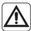
1.2 - IDENTIFICATION OF THE MAIN COMPONENTS (Fig.A)
- Control panel
- Air outlet grille
- Flap
- IR remote control receiver
- Wheels
- Handel
- Air filter grille
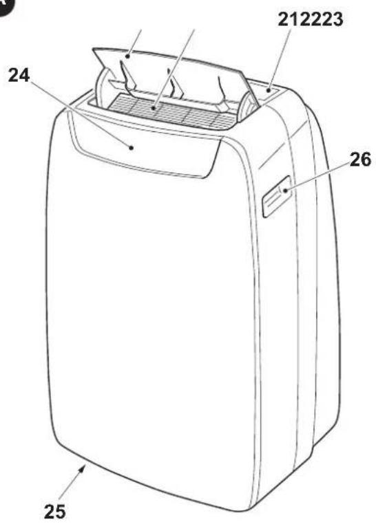
27a. Air filter - Condensation drain cap (for use as dehumidifier)
-
Air inlet grille
-
Extractable air filter
- Hole for plug housing
- Cap for condensation emptying (in case of transport, maintenance or excessive accumulation of water)
- Cable winder
- Power supply cable
- Condensation drain cap (only for version with heat pump)
- Air outlet grille
A
EN - 11
2 - INSTALLATION
2.1 - HOW TO TRANSPORT THE CONDITIONER
Transport and handling of the appliance must be carried out in vertical position.
- If it is transported in a horizontal position, wait at least one hour before starting it.
- Before moving or transporting the appliance, completely drain condensation by working as described in paragraph 4.2.a

CAUTION
Moving the air conditioner on delicate flooring (e.g. wooden flooring):
Completely drain condensation.
• Take great care when moving the conditioner as the wheels could mark the flooring. Although the wheels are made from a rigid material and are swivelling, they could get damaged by use or excessive dirt.
It is recommended to check that the wheels are clean and that they can move freely.
2.2 - WARNINGS

A failure to respect what follows may cause damages to the appliance.
a. Install the air conditioner on flat and stable surfaces and on the floor.
b. Only connect the air conditioner to power sockets equipped with a ground system.
c. Make sure that curtains or other objects do not obstruct the air suction filters (Fig.7).
d. Make sure to keep a minimum distance of 30 cm (Fig.1) between the air conditioner and the adjacent figures.
e. The appliance must always be activated paying attention that there are no obstacles for air suction and output.
f. The air conditioner must not be used in laundries.
g. The air conditioner must be installed in a dry place only.
h. The air conditioner must not be started in presence of dangerous materials, steams or liquids.
i. Clean the air filters at least once a week.
2.3 - MOBILE INSTALLATION
The air conditioner must be installed in a suitable environment. It is recommended to reduce solar radiation through curtains, Venetian blinds and to keep doors and windows closed.
a. Position the air conditioner in front of a window or French window.
b. Position the machine side terminal (2) on the flexible hose (1) as shown by Fig.8.
c. Position the terminal (3) on the opposite side of the flexible hose (1) (Fig.8).
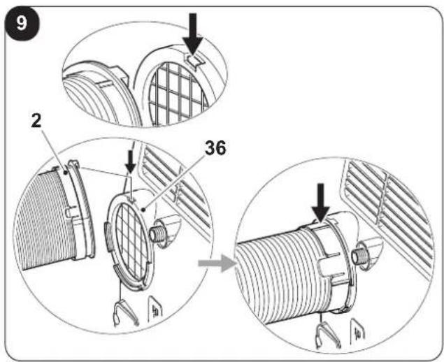
d. Insert the machine side terminal (2) on the air outlet grid of the appliance (36) as shown in figure 9.
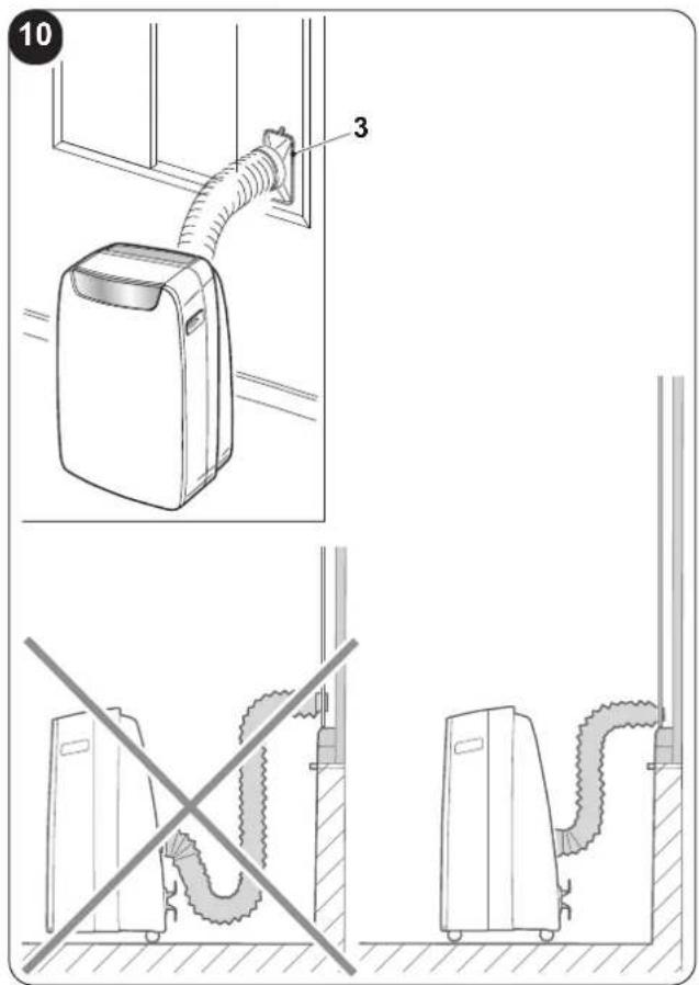
e. Position the terminal (3) in such a way as to make air exit to the exterior (Fig.10)
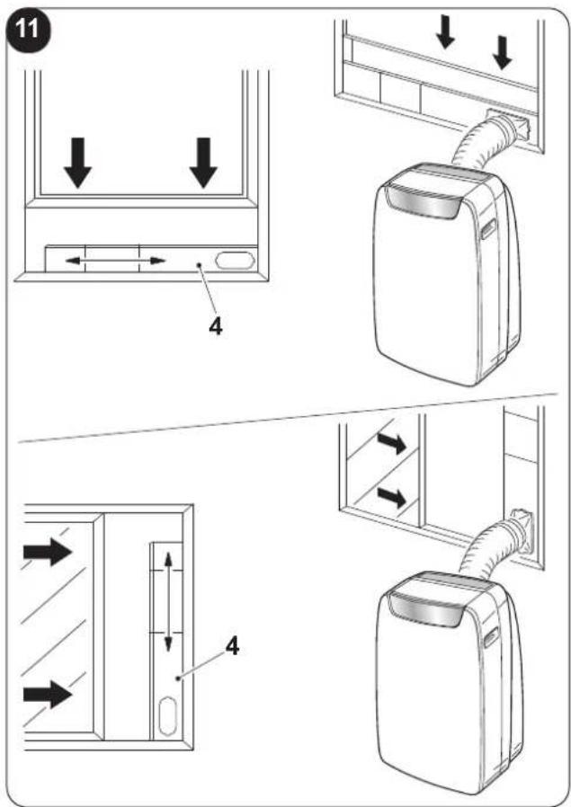
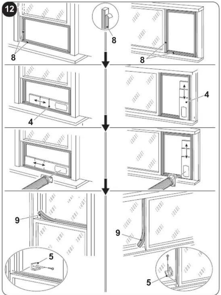
f. If you possess a sliding window (vertical or horizontal) or a shutter, it is possible to use the supplied "SLIDER KIT" (4) which allows a more efficient installation.
For the installation with KIT SLIDER, proceed as shown in figures 11 and 12.
g. Apply the adhesive seal (8) (Fig.12)
h. Position the "SLIDER KIT" (4) and adapt it (Fig.12)
i. Position the flexible hose (1) and apply the seal (9) (Fig.12)
I. If desired, position the locking bracket (5) (Fig.12)

Extend the pipe only to the necessary extent, so that the air conveyor remains closed between the fixture shutters.
EN - 12

OLIMPIA
SPLENDID
2.4 - FIXED INSTALLATION
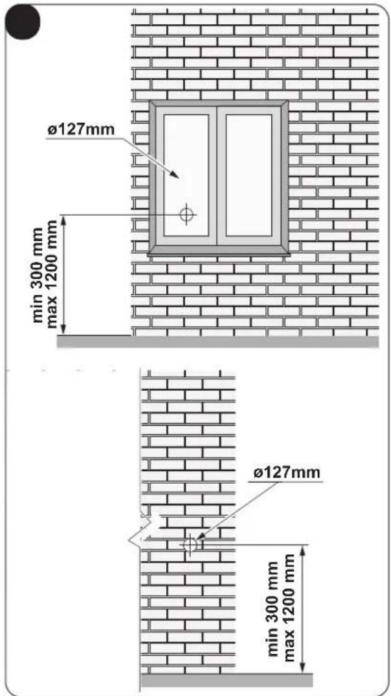
The air conditioner can also be installed with fixed holes in windows or walls. Air flow must not be obstructed by protective mesh or similar. Any forms of protection must have a total cross-section for air flow of not less than 140 cm^2 .
a. Position the machine side terminal (2) on the flexible hose (1) as shown by Fig.8.
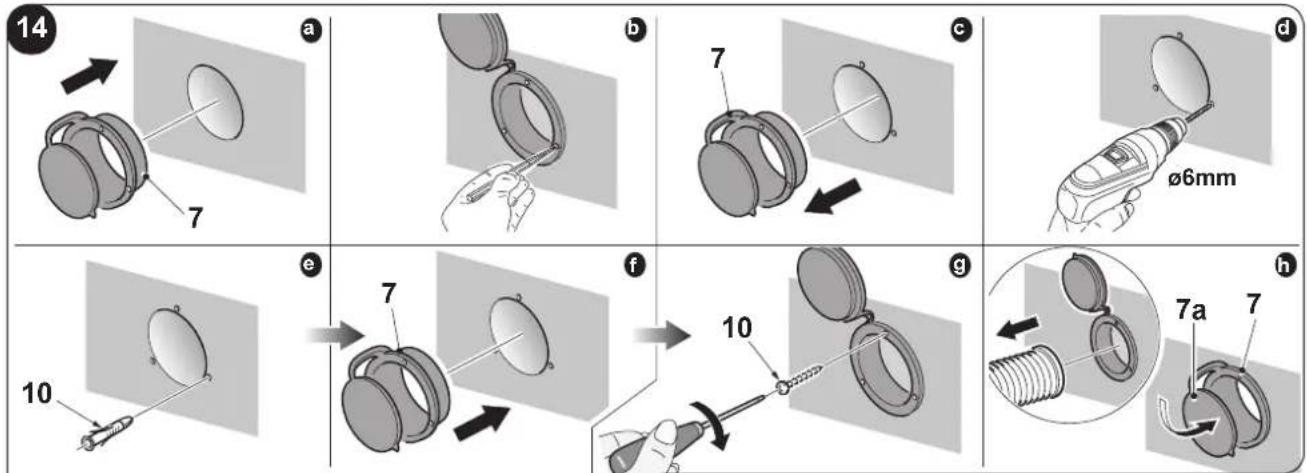
b. Drill a 127 mm hole in the glass or in the wall at a height above the floor included between 300 and 1200 mm (Fig.13).
c. Position the terminal (7) in the wall hole and mark the drilling points (Fig. 14-a, 14-b).
d. Remove the terminal (7) and drill 6 mm holes (Fig. 14-c, 14-d).
e. Insert the supplied wallplugs (10) in the holes (Fig. 14-e).
f. Position the terminal (7) in the hole of the wall and fix it with the supplied screws (10) (Fig. 14-f, 14-g).
g. Insert the machine side terminal (2) on the air outlet grid of the appliance (36) as shown in figure 9.
h. Connect the other extremity of the flexible hose (1) on the terminal (7) (Fig.14-i).
i. Close the cap (7a) when the appliance is not running (Fig.14-h).
2.5 - ELECTRICAL CONNECTION
The appliance is fitted with a power cable with plug.
Before connecting the air conditioner ensure that:
- The voltage and power frequency values match those specified on the appliance plate data.
- The power line is equipped with an effective earth connection and is correctly sized for maximum power consumption of the air conditioner.
- The appliance's power network must be equipped with a suitable omnipolar disconnection device compliant with national installation regulations.
- The appliance is powered solely through a socket compatible with the plug provided.
natural_image
Illustration of a hand using a power plug to install an electrical socket (no text or symbols present)
CAUTION
replacement of the power cable must be carried out solely by Olimpia Splendid technical support or by similarly qualified personnel.
2.6 - DRAINAGE
Depending on the modality of use of the appliance, it is necessary to connect the condensation discharge pipe.
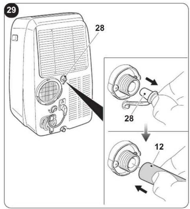
2.6.a - Use as dehumidifier
For the correct use of the appliance, work as follows (figures 29 and 32):
a. Remove the cap (28).
b. Insert the supplied pipe (12) in the connector.

Make sure the end of the discharge pipe (12) is positioned on a drain well or in a container.
ke sure the pipe (12) is not clogged.
c. If necessary, apply the terminal (13) to the condensation discharge pipe (12).
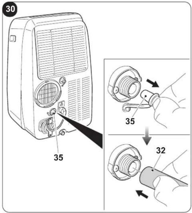
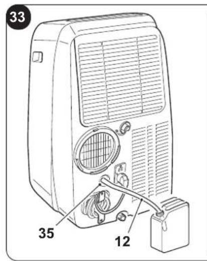
2.6.b - Use as heat pump
(only for the suitable version)
For the correct use of the appliance, work as follows (figures 30 and 33):
a. Remove the cap (35).
b. Insert the supplied pipe (12) in the connector.

Make sure the end of the discharge pipe (12) is positioned on a drain well or in a container.
ake sure the pipe (12) is not clogged.
c. If necessary, apply the terminal (13) to the condensation discharge pipe (12).
3 - USE OF THE APPLIANCE
The functioning modes if the air conditioner can be selected both through the remote control and through the control panel located on board of the air conditioner.
The reception of the selected function is confirmed by the emission of a "beep" by the buzzer.
3.1 - CONTROL PANEL SYMBOLS AND KEYS (Fig.B)
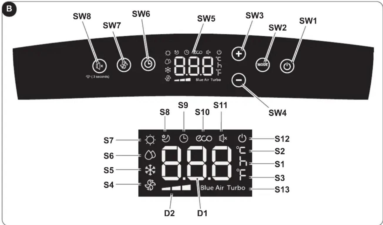
- SW1: ON/Stand-by;
- SW2: Operation mode selection
ECO - Blue air (auto) =>
=> fan only =>
=> dehumidification =>
=> heating
(active only in the version with heat pump) =>
=> cooling =>
=> turbo cooling => ...
- SW3: Temperature/delay increase
- SW4: Temperature/delay decrease
- SW5: Display
- SW6: Confirmation/cancellation unit switching on/off delay
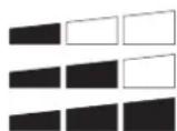
• SW7: Fan speed selection
Minimum speed =>
=> Medium speed =>
=> Maximum speed =>
=> Blue air (auto)
- SW8: "SILENT" function selection (silent) /
Wi-Fi Search
• D1: Set temperature/Timer
• D2: Fan speed indication (see "SW7")
• S1: Hour indicator
• S2: Temperature indicator in °C
• S3: Temperature indicator in F
- S4: Fan only mode
• S5: Cooling mode
• S6: Dehumidification mode
- S7: Heating mode (active only in the version with heat pump)
• S8: Sleep mode
• S9: Timer mode (programmed switching on/off)
• S10: Automatic mode (ECO)
• S11: "Silent" function active
• S12: Appliance electrically powered indicator
• S13: Turbo function
EN - 14
3.2 - REMOTE CONTROL KEYS (Fig. C)
C
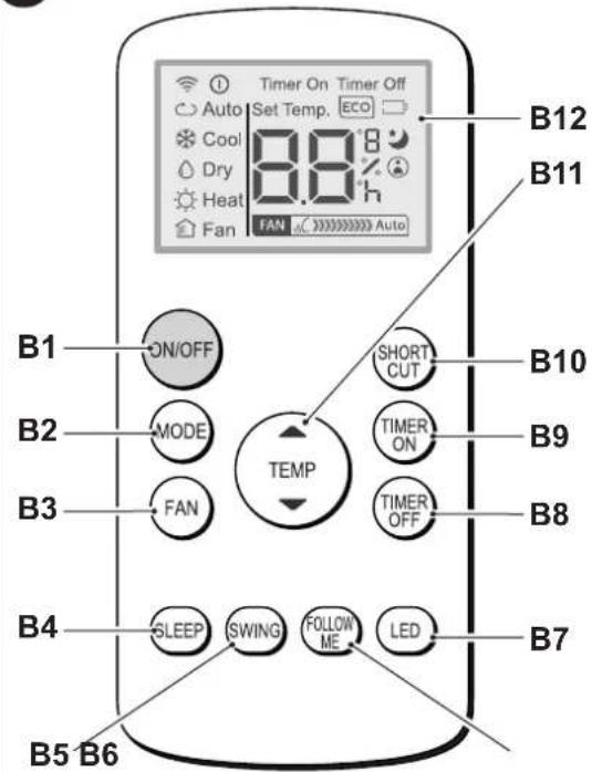
• B1: On/Off key for the appliance switching on/off
- Symbol (D1) turned on: appliance On
- Symbol (D1) turned off: appliance in Stand-by
• B2: Operation mode selection
AUTO (Automatic) ECO =>
=> cooling =>
=> dehumidification =>
=> heating (active only in the version with heat pump) =>
=> fan only => ...
• B3: Fan speed selection
Minimum speed =>
=> Medium speed =>
=> Maximum speed
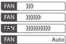
=> Auto
• B4: SLEEP mode activation (ON/OFF)
• B5: DISABLED
• B6: Activate/deactivate FOLLOW ME function
• B7: Activate/deactivate display on machine control panel
• B8: Unit switch OFF delay setting
• B9: Unit programmed switch-on setting
• B10: SHORT CUT
• B11: Temperature set increase ▲
Temperature set decrease ▼
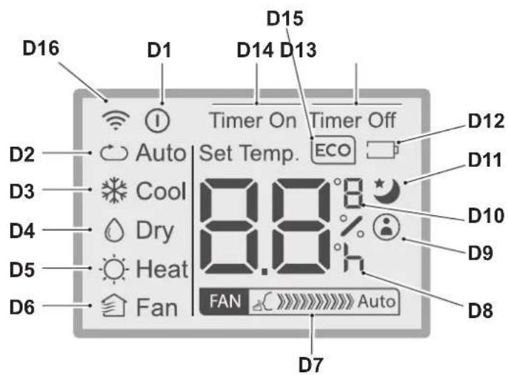
• B12: Display
• D1: Appliance running indicator
• D2: Automatic mode (ECO)
• D3: Cooling mode (COOL)
• D4: Dehumidification mode (DRY)
• D5: Heating mode (HEAT) (active only in the version with heat pump)
• D6: Fan only mode (FAN)
• D7: Fan speed indication (vederte "B3")
• D8: Programmed switching on/off "hour" indicator
• D9: "FOLLOW ME" function active indicator
• D10: Temperature indicator in °C (F)
• D11: "SLEEP" function active indicator
• D12: Remote control battery low indicator
• D13: "TIME OFF" function active indicator
• D14: "TIME ON" function active indicator
• D15: “ECO” function active indicator
• D16: Remote control transmission signal
3.3 - USE OF THE REMOTE CONTROL
The remote control supplied with the air conditioner is the tool which allows You to use the appliance in the most comfortable manner.
It should be handled with care and in particular:
- Keep it dry (do not clean it with water or leave it outdoors in bad weather).
- Avoid dropping or bumping it.
- Keep it out of direct sunlight.

- The remote control operates by means of an infrared beam.
During use, there must not be any obstacle between the remote control and the air-conditioner.
- If other appliances in the room have remote controls (TV, stereo, etc...), there may be interference.
- Electronic and fluorescent lights may also interfere with transmissions between remote control and air-conditioner.
- Remove the batteries in case of prolonged disuse of the remote control.
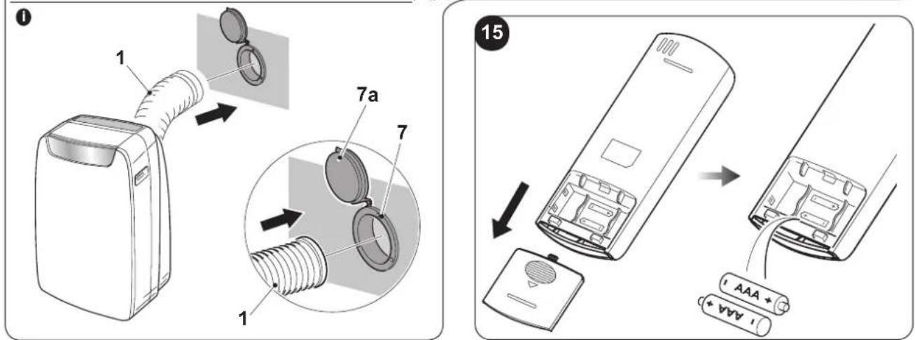
3.3.a - Insertion of batteries
To insert the batteries correctly:
a. Remove the batteries compartment cover (figure 15).
b. Insert the batteries into the relevant compartment (figure 15).

Check the polarity indicated on the bottom of the compartment.
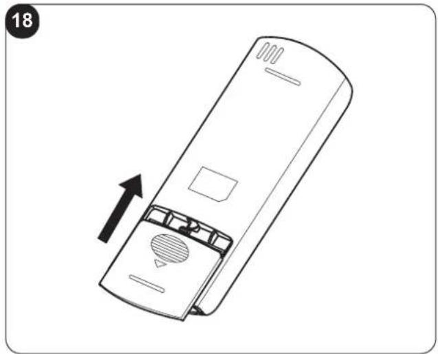
c. Close the compartment correctly (figure 18).
3.3.b - Replacement of batteries
The batteries must be replaced when the icon ☐ appears on the display.

Always use new batteries. The use of old or different batteries could generate malfunctioning of the remote control.
The remote control uses two dry alkaline 1.5V batteries (AAA.) (Fig.15).

When replacing batteries, replace both and dispose of the dead batteries in the appropriate collection centres and as required by law.
- If the remote control is not used for several weeks or longer, remove the batteries. Any leaks from the batteries could damage the remote control.

Do not re-charge or disassemble the batteries. Do not throw the batteries into the fire. Can burn and explode.

If the battery liquid falls onto the skin or clothes, wash well with clean water. Do not use the remote control with batteries that have leaked. The chemical products contained in the batteries can cause burns or other risks to health.
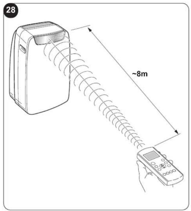
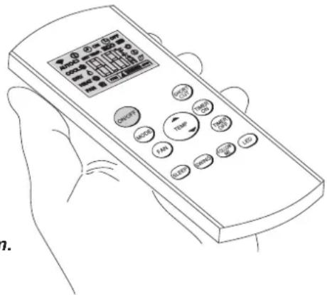
3.3.c - Location of the remote control
- Keep the remote control in a position from which the signal can reach the receiver (24) of the appliance (maximum distance is approx. 8 metres - with charged batteries) (figure 28).
The presence of obstacles (furniture, curtains, walls, etc.) between the remote control and the appliance reduces the remote control range.
EN - 16
3.4 - USE OF THE APPLIANCE
Work as follows in order to use the appliance.

To prevent possible damages to the compressor, each start is delayed by 3 minutes with respect to the last switching off.
3.4.a - Preliminary operations
- Place the appliance on a stable and not inclined base, at at least 20/30 cm. from the wall or from any other object, in order to ensure the correct air circulation. (Fig.1). Place it on a water-resistant surface since the possible water leakage could damage furniture or the floor.
- Do not place the appliance directly on carpets, towels, blankets or other absorbent surfaces.
- Insert the plug in the power socket. The appliance emits a “beep”, on the display appears the icon ⏻ and the environment temperature in °C.

Before electrically connecting the appliance, make sure the plate data correspond to those of the electricity distribution network.
3.4.b - Appliance switching on/off
a. To start the appliance, press the key "ON/OFF" on the remote control or the key ⏻ on the control panel.
b. A beep warns that the appliance is in operation and the flap (23) raises.
c. The icon ⏻ switches on on the control panel.
d. appears on its display ① appears on its display.
e. In case of prolonged stop of the appliance, it must be reset by removing the plug from the power socket, wait 5÷10 seconds and then reinsert it; a beep signals that the appliance is ready for use.
3.5 - AUTO MODE (Automatic)
a. When this mode is selected, the appliance automatically activates the COOLING, HEATING (only for version with heat pump) or FAN functions depending on the environment temperature and on the set one. The environment temperature is continuously checked to obtain an optimal comfort in the air conditioned room.
b. This mode can be selected by pressing the key "MODE" once or more (on the remote control or on the control panel) until when the specific icon ECO and Blue Air is shown on the display of the control panel and/or when the icon Auto appears on the remote control display.
c. It is not possible to select the fan speed in AUTO mode.
3.6 - COOLING MODE (COOL)
a. When this mode is selected, the appliance dehumidifies and cools the environment.
This mode can be selected by pressing the key "MODE" once or more (on the remote control or on the control panel) until when the specific icon ✦ appears on the display.
b. In this mode, the fan is always switched on and it is possible to select its desired speed by pressing the key "FAN" on the remote control or the key ⚙ on the control panel.
The fan speed is displayed as indicated in paragraphs "3.1" (point SW7) and "3.2" (point B3).
c. The temperature set-point is included between 17°C and 30°C (from 62 F and 86 F) with 1°C variations and it can be set using the keys +/- on the control panel or with the keys ▲ ▼ on the remote control.
d. After a certain time (maximum three minutes) after the activation of the operation mode, the compressor activates and the appliance starts delivering cold air.
EN - 17
3.7 - TURBO COOLING MODE
- This function can be activated only from the control panel of the appliance.
a. This mode can be selected by pressing key "MODE" once or more on the control panel until the icons and "Turbo" appear on the display.
b. The function sets the appliance directly to cooling mode with a temperature of 17^ C and maximum speed of the fan in order to reach the set temperature more quickly.
c. In this mode it is not possible to select either the fan speed and the temperature.
d. To switch off the function, press key "MODE" on the control panel or switch off the appliance.
3.8 - DEHUMIDIFICATION MODE (DRY)
a. When this mode is selected, the appliance dehumidifies the environment.
This mode can be selected by pressing the key “MODE” once or more (on the remote control or on the control panel) until when the specific icon appears:
- 🎨 on the control panel - 🔊 on the remote control display.
b. In DRY mode, it is not possible to select the fan speed or to adjust temperature.
The fan motor works at low speed.
c. Keep doors and windows closed to achieve the best dehumidifying effect.
Do not place the air outlet pipe out of a window.
d. Connect the condensation discharge pipe (paragraph 2.6.a)
3.9 - VENTILATION MODE (FAN)
a. When this mode is selected, the appliance doesn't perform any action both on temperature or on air humidity in the environment, but only maintains it in circulation.
b. This mode can be selected by pressing the key "MODE" once or more (on the remote control or on the control panel) until when the specific icon is shown on the display of the control panel and/or of the remote control.
- 🧑 icon on the control panel - 🏠 icon on the remote control display
c. In this mode, the fan is always switched on and it is possible to select its desired speed by pressing the key "FAN" on the remote control or the key ⚙️ on the control panel.
d. The fan speed is displayed as indicated in paragraphs "3.1" (point SW7) and "3.2" (point D7).
3.10 - HEATING MODE (HEAT)
(only for version with heat pump)
a. When this mode is selected, the appliance heats the environment.
b. This mode can be selected by pressing the key "MODE" once or more (on the remote control or on the control panel) until when the specific icon ⚙ is shown on the display.
c. In this mode, the fan is always switched on and it is possible to select its desired speed by pressing the key "FAN" on the remote control or the key ⚙️ on the control panel.
The fan speed is displayed as indicated in paragraphs "3.1" (point SW7) and "3.2" (point D7).
d. The temperature set-point is included between 17°C and 30°C (from 62 F and 86 F) with 1°C variations and it can be set using the keys +/- on the control panel or with the keys ▲ ▼ on the remote control.
e. After a certain time (maximum three minutes) after the activation of the operation mode, the heat pump activates and the appliance starts delivering warm air.
f. Connect the condensation discharge pipe (paragraph 2.6.b)
3.11 - TIMER MODE
a. This mode allows to program the switching on or the switching off of the appliance.
b. The delay time can be set, activated and cancelled both from the remote control and from the control panel.
3.11.a Programmed switching on
a. When the appliance is in standby mode, select the operation mode, the desired temperature and ventilation speed.
- On the control panel: - press Ⓤ and set the switching on delay time with the keys +/-
- To activate the function, press 📋 or wait approximately 5 seconds so that the set time on the display stops flashing (the display returns to showing the environment temperature).
The icon
L lights up.
- On the remote control: - press the key "TIMER ON" to access the function and then press the key "TIMER ON" once or more until the switching on delay time is set.
- Direct the remote control towards the appliance; a beep confirms the activation of the function.
- The icon
On the control panel and the indicator "Timer On" on the remote isplay light up.
b. Once the set time has passed, the appliance starts with the same settings (mode, temperature and ventilation speed) as those before switching off.
c. Time can be set with 30 minutes steps up to 10 hours and with 60 minutes steps from 10 to 24 hours.
d. Starting the appliance or adjusting the timer setting to "0.0h" will cancel the programmed switching on function.
3.11.b - Programmed switching off
a. When the appliance is running, set the delayed switching off time.
- On the control panel: - press Ⓤ and set the switching off delay time with the keys +/-
- To activate the function, press Ⓞ or wait approximately 5 seconds so that the set time on the display stops flashing (the display returns to showing the environment temperature).
The icon
① lights up.
- On the remote control: - press the key "TIMER Off" to access the function and then press the key "TIMER Off" once or more until the switching off delay time is set.
- Direct the remote control towards the appliance; a beep confirms the activation of the function.
- The icon ⏱ on the control panel and the indicator "Timer Off" on the remote control display light up.
b. Once the set time has passed, the appliance switches off.
c. Time can be set with 30 minutes steps up to 10 hours and with 60 minutes steps from 10 to 24 hours.
d. Switching off the appliance or adjusting the timer setting to "0.0h" will cancel the programmed switching off function.
3.12 -OTHER FUNCTIONS
3.12.a - SILENT function
- This function can only be activated from the control panel of the appliance.
a. When the appliance is working, press key SW8 (speaker); The speaker symbol appears.
Ventilation speed automatically sets itself to minimum.
b. Press the key again to deactivate the function.
3.12.b - SLEEP function
- This function can be activated only from the remote control.
- This function is not available while the Dehumidification (DRY) and Fan Only (FAN) modes are active.
a. When the appliance is running, press the key "SLEEP" on the remote control.
The icon 🙏️ appears on the control panel and on the remote control display.
The appliance will decrease (when cooling) or increase (when heating) the set temperature by 1^ C (1 or 2 F) for 30 minutes.
EN - 19
b. Then, the appliance will decrease (when cooling) or increase (when heating) the set temperature by 1^ C (1 or 2 F) for an additional 30 minutes.
c. This temperature will be maintained for 7 hours before returning to the originally selected temperature.
Once this time has passed, the appliance will restart working as originally programmed.
d. Press the key "SLEEP" on the remote control to stop the function; the icon on the control panel and on the remote control display turn off.
3.12.c - FOLLOW ME function
- This function can be activated only from the remote control.
- This function is not available while the Dehumidification (DRY) and Fan Only (FAN) modes are active.
In this function, the remote control serves as a thermostat.
a. When the appliance is running, press the key "FOLLOW ME" on the remote control.
b. Move with the remote control in an area of the room different from where the appliance is positioned (maximum distance is 7 ÷ 8 metres) directing it towards the appliance itself and making sure there are no obstacles between them.
c. Set the desired temperature on the remote control; the appliance works until it takes the temperature of the area where the remote control is positioned to the value set on the remote control itself.
d. The remote control sends a signal to the appliance and, if it doesn't receive a response within a maximum time of 7 minutes, the function deactivates.
e. Press the key "FOLLOW ME" on the remote control or switch the appliance off to stop the function.
3.12.d - Setting the unit of measurement of temperature
It is possible to choose the set and environment temperature unit of measurement choosing between ^ C (Celsius) or F (Fahrenheit).
Work as follows:
- On the control panel, press the keys + and - at the same time for approximately three seconds. The desired unit of measurement appears on the display of the control panel.
- On the remote control, keep the central key TEMP pressed for approximately three seconds. The desired unit of measurement appears on the display of the remote control.

The unit of measurement change must be performed both on the control panel and on the remote control.
3.12.e - Directing the air flow
- This function can be activated only from the remote control.
a. When the appliance starts, the flap opens completely.
b. Press the key "SWING" on the remote control and the flap starts oscillating automatically.
c. Press the key "SWING" to stop the flap in a certain position.
Press it again to restart oscillation.
3.12.f - Short Cut function
- This function can be activated only from the remote control.
a. When the appliance is running in any of its modes, press the key "SHORT CUT" on the remote control and the appliance automatically configures itself to "AUTO" with a set temperature of 26^ (80 F).
3.12.g - Auto-Restart
a. If the appliance switches off due to interruption of power supply, it automatically restarts with the previous settings when electrical power is restored.
3.12.h - Wi-Fi
a. Press SW8 for approximately 3 seconds to activate the "Wifi" function, on the display appears the message "AP" waiting for connection to the device.
EN - 20
4 - MAINTENANCE AND CLEANING

Before proceeding with any maintenance and cleaning intervention, always make sure you disconnected the power plug from the power socket.
natural_image
Illustration of a hand using a power plug to insert an electrical socket (no text or symbols present)
Do not touch the metal parts of the appliance when you remove the filter.
There is a risk of injury due to the sharp metal edges.

Do not use water to clean the internal parts of the air conditioner. sure to water can ruin the isolation, with the risk of electric shocks.
4.1 - CLEANING
4.1.a - Cleaning the appliance and the remote control
a. Use a dry cloth to clean the appliance and the remote control.
b. It is possible to use a cloth moistened with cold water to clean the appliance in case it's very dirty.

Do not use a chemically treated or antistatic cloth to clean the appliance.

Do not use gasoline, solvent, polish or similar solvents. The products could cause the breakage or deformation of the plastic surface.
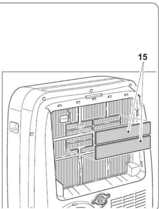
4.1.b - Air filters maintenance
The filter system consists of a mesh filter (fig. 34 ref. 27a) and a series of additional filters that the user can choose from (fig. 34 ref. 15).
To ensure the indoor air is filtered correctly and to guarantee that your air conditioner runs efficiently, it is vital to clean the air filters regularly.

The additional filters must be changed after around 500 working hours.
In order for the filter system to work correctly only original spare parts should be used.
4.1.c - Cleaning the air filter
A dirty air filter reduces the cooling capacity of the appliance.
Please clean the filter once every 2 weeks.
a. Release the grille (27) together with the filter (27a) and raise it to remove it from the appliance (Fig.19).
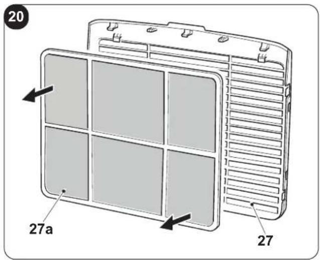
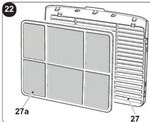
b. Remove the filter (27a) from the grille (27) (Fig.20).
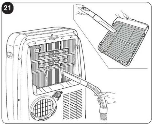
c. Clean the filter (27a) using a vacuum cleaner or wash it with water, then let it dry in a fresh environment.

Provide for the filter (27a) replacement if it is damaged.
d. Make sure the filter (27a) has dried completely.
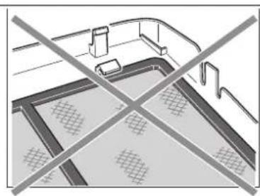
e. Reposition the filter (27a) in the grille (27) paying attention to its correct positioning (Fig. 22).
f. Suck possible fluff from the plates (Fig. 21).
g. Position the grille (27) together with the filter (27a) on the appliance body making sure it is correctly hooked.

Do not use the appliance without the filter (27a).
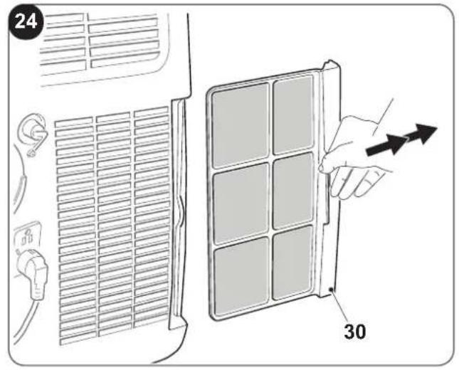
4.1.d - Cleaning the suction filter
A dirty suction filter reduces the appliance performances.
Please clean the filter once every 2 weeks.
a. Remove the filter (30) laterally (Fig.24).
b. Clean the filter (30) using a vacuum cleaner or wash it with water, then let it dry in a fresh environment.

Provide for the filter (30) replacement if it is damaged.
c. Make sure the filter (30) has dried completely.
d. Correctly reposition the filter (30) in its specific seat (Fig. 25).
e. Suck possible fluff from the grille (Fig. 25).

Do not use the appliance without the filter (30).
4.1.e - RECOMMENDATIONS FOR ENERGY SAVING
Below find simple recommendations for reducing consumption:
- Always and constantly keep the filters clean (see maintenance and cleaning chapter).
- Keep the doors and windows of the rooms to be climate controlled closed.
- Do not let sun rays penetrate freely into the room (we recommend using curtains or lowering blinds or closing the shutters).
- Do not obstruct the air flow path (input and output) of the appliance; this, in addition to obtaining a non-optimal yield, also affects the correct operation of the appliance and the possibility of irreparable damages to the appliance itself.
4.2 - MAINTENANCE
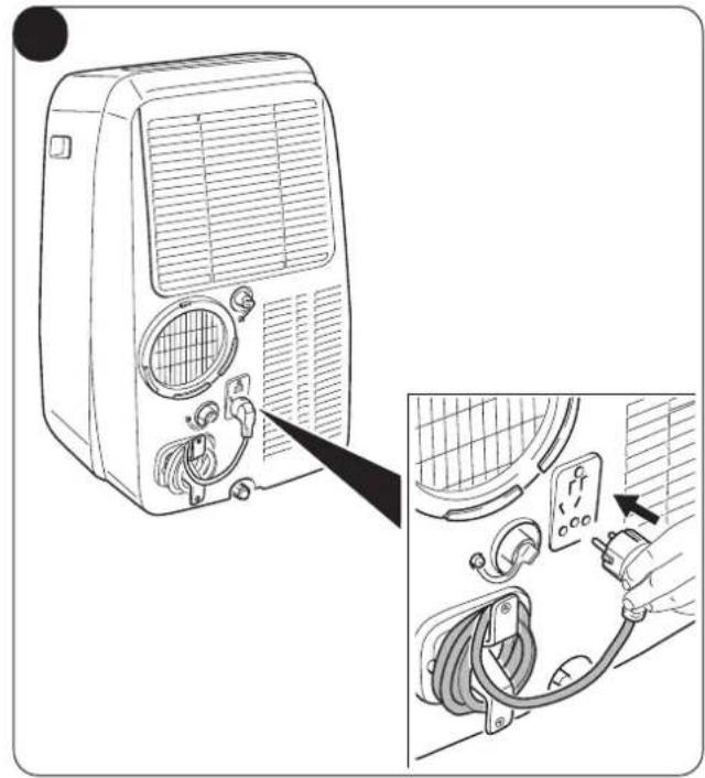
If you do not intend to use the appliance for a long period of time, work as follows:
a. Activate the fan only mode for a few hours (approximately 1÷2 hours) to dry the interior of the appliance.
b. Stop the air conditioner and disconnect the power supply.
c. Clean the air filters.
d. Completely discharge condensation.
e. Wrap the power supply cable (34) around the cable winder (33) and insert the plug in the specific housing (31) (Fig.31).
f. Remove the batteries from the remote control.
Checks before resuming use of the air conditioner:
a. Clean the filters after a long period of inactivity of the air conditioner.
b. Check that the air outlet or inlet are not obstructed (especially after a long period of inactivity of the air conditioner).
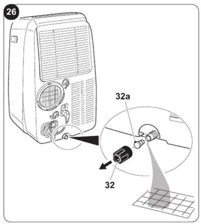
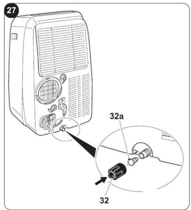
4.2.a - Discharging condensation
When condensation in the lower tray reaches the predetermined level, the appliance emits 8 beeps; "P1" appears on the control panel and the appliance stops working (the fan motor keeps running). In this case:
a. Disconnect the plug from the power socket.
b. Carefully move the appliance in position suitable to unload water.
c. Remove the drain cap (32) and the rubber cap (32a) (Fig.26).

Make sure you correctly tightened the drain cap (32) in order to avoid water leak.
d. Make water unload completely.
e. Reposition the rubber cap (32a) and screw the drain cap (32) (Fig.27).
f. Insert the plug in the power socket and restart the machine until when the indicator "P1" turns off.

If the error repeats, please contact an Assistance Centre.
EN - 22
4.2.b Error codes
During the appliance functioning, a few anomalies which stop its functioning could appear. In these cases, some error codes appear on the control panel.
• P1 Lower tray full.
- Empty it by operating as described in paragraph 4.2.a
• F1 Filters cleaning.
- Message F1 appears every 250 hours of operation of the fan motor.
Proceed with the filters cleaning (paragraphs 4.1.b - 4.1.c - 4.1.d) and reset the hours counting by keeping key "ON/OFF" on the appliance control panel pressed for 5 seconds.
• E1 Environment temperature sensor error.
• E2 Evaporator temperature sensor error.
• E3 Condenser temperature sensor error
• E4 Display panel communication error.
In these cases:
a. electrically disconnect the appliance
b. wait a few minutes
c. connect the plug to the power socket
d. restart the appliance.

If the inconvenience persists and the error code doesn't turn off, electrically disconnect the appliance and refer to an Assistance Centre.
5 - TECHNICAL DATA
For the technical data, please consult the data plate applied to the product (Fig.2).
| • Dimensions (W x H x D) 490 x 765 x 425 mm | |
| • Working temperature limits in Cooling function 17°C÷35°C (62 F ÷ 95 F) | |
| • Working temperature limits in Dehumidification function | 13°C÷35°C (55 F ÷ 95 F) |
| • Working temperature limits in Heating mode (heat pump) | 5°C÷30°C (41 F ÷ 86 F) |
| • Refrigerant gas R290 | |
6 - WIRING DIAGRAM
The wiring diagram shown in image 35.
OPTIONAL
This symbol indicates the element is optional.
7 - INCONVENIENCES AND POSSIBLE REMEDIES
| MALFUNCTIONThe appliance doesn't work. | CAUSENo power.The plug has not been inserted. | WHAT DO I DO?Wait.Insert the plug in the power socket. |
| The appliance doesn't switch on. | P1 Error CodeIn COOLING mode: environment temperature is lower than the set temperature | The water collection tray is full.Switch off the appliance, unload water from the collection tray and then restart the appliance.Reset temperature. |
| The appliance only works for a small amount of time. | The temperature set is too close to ambient temperature.Suction of outside air is obstructed. | Lower the temperature set.Remove the obstructions.Call the Service Centre. |
| The appliance doesn't cool efficiently. | The air filters are clogged by dust, fluff or animal hair.The drain pipe not connected or it is clogged.The appliance has a low level of refrigerant.Temperature setting is too high.The windows or doors of the room are open.The room area is too large.Heat sources are present inside the room. | Switch off the appliance and clean the filters following the instructions.Switch off the appliance, disconnect the pipe, remove the possible obstruction and reconnect the drain pipeContact an assistance centre to have the appliance inspected and the refrigerant topped-up.Reduce the set temperature.Make sure all the windows and the doors are closed.Check the cooling area again.Remove the heat sources if possible. |
| The appliance is noisy and vibrates excessively. | The appliance bearing surface is not levelled.The air filters are clogged by dust, fluff or animal hair. | Place the appliance on a flat and levelled surfaceSwitch the appliance off and clean the filters following the instructions. |
| The appliance emits an abnormal sound. | This sound is caused by the refrigerant flow inside the unit. | It is totally normal. |
| Water leaks from the conditioner during transport. | The conditioner has been tilted or laid flat. | Empty water before moving the appliance. |
| In cooling, night-time or automatic mode, minimum speed cannot be selected. | Ambient temperature too low. | Air conditioner behaviour is normal. |
Do not try to repair the appliance by yourself.
If the problem has not been solved, please contact your local retailer or the closest assistance service. Supply detailed information about the malfunction and the equipment version.
EN - 24
0 - MISES EN GARDE....2
0.1 - INFORMATIONS GÉNÉRALES ......2
0.2 - SYMBOLOGIE .... 2
0.2.1 - Pictogrammes rédactionnels ......2
0.3 - MISES EN GARDE GÉNÉRALES ....3
0.4 - UTILISATION PRÉVUE....5
0.5 - ZONES À RISQUE....6
0.6 - AVERTISSEMENTS POUR LE GAZ
RÉFRIGÉRANT R290....6
1 - DESCRIPTION DE L'APPAREIL .....11
1.1 - LISTE DES COMPOSANTS FOURNIS ..... 11
1.2 - IDENTIFICATION DES PARTIES
PRINCIPALES....11
2 - INSTALLATION ....12
2.1 - TRANSPORT DU CLIMATISEUR .....12
2.2 - MISES EN GARDE .....12
2.3 - INSTALLATION MOBILE 12
2.4 - INSTALLATION FIXE ......13
2.5 - RACCORDEMENT ELECTRIQUE....13
2.6 - DRAINAGE....13
natural_image
Illustration of a hand using a power plug to switch an electrical outlet (no text or symbols)
RECOMMANDATION
natural_image
Illustration of a hand using a power plug to switch an electrical outlet (no text or symbols present)
2.3 - BEWEGLICHE INSTALLATION
natural_image
Illustration of a hand using a power plug to insert an electrical socket (no text or symbols)
Hinweis
=> Kühlen =>
=> Turbo-Kühlung => ...
natural_image
Hand using a power plug to switch an electrical outlet (no text or symbols visible)
natural_image
Illustration of a hand using a power plug to switch an electrical outlet (no text or symbols)
Advertencia
=> Velocidad media =>
=> Velocidad máxima
=> Blue air (auto)

natural_image
Illustration of a hand using a power plug to switch an electrical outlet (no text or symbols present)
4.2 - MANUTENÇÃO....22
7 - PROBLEMAS E POSSÍVEIS SOLUÇÕES.....24
0 - ADVERTÊNCIAS
0.1 - INFORMAÇÕES GERAIS
a. Instale o climatizador sobre superfícies planas, estáveis e à altura do piso.
natural_image
Illustration of a hand using a power plug to switch an electrical outlet (no text or symbols)
Advertência

natural_image
Illustration of a hand using a power plug to switch an electrical outlet (no text or symbols present)
7 - PROBLEMAS E POSSÍVEIS SOLUÇÕES
0 - WAARSCHUWINGEN 2
0.1 - ALGEMENE INFORMATIE....2
0.2 - SYMBOLEN 2
0.2.1 - Redactionele pictogrammen.....2
0.3 - ALGEMEEN ADVIES ....3
0.4 - BEOOGD GEBRUIK 5
0.5 - RISICOZONES....6
0.6 - WAARSCHUWINGEN VOOR HET
KOELGAS R290....6
1 - OMSCHRIJVING VAN HET APPARAAT .....11
1.1 - LIJST VAN DE MEEGELEVERDE
ONDERDELEN .... 11
1.2 - IDENTIFICATIE VAN DE VOORNAAMSTE
ONDERDELEN .... 11
2 - INSTALLATIE ....12
2.1 - TRANSPORT VAN DE AIRCONDITIONER .12
2.2 - WAARSCHUWINGEN....12
2.3 - MOBIELE INSTALLATIE ....12
2.4 - VASTE INSTALLATIE....13
2.5 - ELEKTRISCHE AANSLUITING....13
2.6 - DRAINAGE....13
0.6 - WAARSCHUWINGEN VOOR HET KOELGAS R290
- HET APPARAAT BEVAT GAS R290 (ONTVLAMBAARHEIDSCATEGORIE A3)
- HET APPARAAT MOET OPGESLAGEN WORDEN IN EEN GOED GEVENTILEERD VER-TREK, WAARVAN DE AFMETINGEN OVEREENKOMEN MET DE MATEN DIE GESPECIFI-CEERD ZIJN VOOR HET GEBRUIK VAN HET APPARAAT.
- HET APPARAAT MOET GEINSTALLEERD, GEBRUIKT EN BEWAARD WORDEN IN EEN RUIMTE WAARVAN HET OPPERVLAK VAN DE VLOER GROTER IS DAN ZIE TABEL.
1 - OMSCHRIJVING VAN HET APPARAAT
1.1 - LIJST VAN DE MEEGELEVERDE ONDERDELEN
2.2 - WAARSCHUWINGEN

natural_image
Illustration of a hand using a power plug to install an electrical socket (no text or symbols present)
WAARSCHUWING
=> turbokoeling => ...

natural_image
Illustration of a hand using a power plug to switch an electrical outlet (no text or symbols present)
natural_image
Illustration of a hand using a power plug to switch an electrical outlet (no text or symbols present)
ΠΡΟΕΙΔΟΠΟΣΗΣΗ
natural_image
Illustration of a hand using a power plug to switch an electrical outlet (no text or symbols present)4.1 - ΚΑΘΑΡΙΣΜΟΣ
natural_image
Illustration of a hand using a power plug to switch an electrical outlet (no text or symbols)
OSTRZEŻENIE
2.3 - INSTALARE MOBILĂ
natural_image
Illustration of a hand using a power plug to switch an electrical outlet (no text or symbols)
AVERTISMENT
- SW1: ON/Stand-by;
- SW2: Selectare mod operare
ECO - Blue air (auto) =>
• B4: Activare mod SLEEP (ON/OFF)
• B5: DEZACTIVAT
3.9 - MOD VENTILATIE (FAN)
2.3 - MOBIL INSTALLATION
natural_image
Illustration of a hand using a power plug to switch an electrical outlet (no text or symbols present)
WARNINGAR
3.9 - VENTILATIONSLÄGE (FAN)
3.12 - MUUT TOIMINNOT....19
5 - TEKNISET TIEDOT ....23
6 - SÄHKÖKAAVIO....23
7 - ONGELMAT JA MAHDOLLISET KORJAUSTOIMENPITEET......24
0 - VAROITUKSIA
0.1 - YLEISTIETOJA
2.3 - SIIRRETTÄVÄ ASENNUS
natural_image
Illustration of a hand using a power plug to switch an electrical outlet (no text or symbols present)
VAROITUS

3.12 -MUUT TOIMINNOT
natural_image
Illustration of a hand using a power plug to switch an electrical outlet (no text or symbols present)
0 - ADVARSLER......2
0.1 - GENERELL INFORMASJON....2
0.2 - SYMBOLER 2
0.2.1 - Redaksjonelle piktogrammer....2
0.3 - GENERELLE ADVARSLER....3
0.4 - TILTENKT BRUK....5
0.6 - RISIKOOMRÅDER....5
0.6 - ADVARSLER FOR KJ∅LEGASS R290 ......6
1 - BESKRIVELSE AV APPARATET .....11
1.1 - LISTE OVER MEDF∅LGENDE
KOMPONENTER.... 11
1.2 - IDENTIFIKASJON AV DE
VIKTIGSTE DELENE 11
2 - INSTALLASJON....12
2.1 - TRANSPORT AV APPARATET .....12
2.2 - ADVARSLER....12
2.3 - MOBIL INSTALLASJON 12
2.4 - FAST INSTALLASJON 13
2.5 - ELEKTRISK TILKOBLING....13
2.6 - AVL∅P 13
2.6.a - Bruk som avfukter 13
2.6.b - Bruk som varmepumpe
(kun for predisponert modell)....13
3 - BRUK AV APPARATET ....14
3.1 - SYMBOLER OG TASTER PÅ
KONTROLLPANELET....14
3.2 - TASTER FJERNKONTROLL....15
3.3 - BRUK AV FJERNKONTROLLEN .....16
4.2 - VEDLIKEHOLD 22
- MERKING AV APPARATET MED SYMBOLER
Referer til lokale lover og regler.
- KASSERING AV APPARATER SOM INNEHOLDER BRENNBARE KJ∅LEVÆSKER
- INFORMASJON OM VEDLIKEHOLD
2.3 - MOBIL INSTALLASJON
natural_image
Illustration of a hand using a power plug to switch an electrical outlet (no text or symbols present)
ADVARSEL
natural_image
Illustration of a hand using a power plug to switch an electrical outlet (no text or symbols present)
2.3. - MOZGATHATÓ TELEPÍTÉS
natural_image
Illustration of a hand using a power plug to switch an electrical outlet (no text or symbols present)
FIGYELMEZTETÉS

natural_image
Illustration of a hand using a power plug to switch an electrical outlet (no text or symbols present)
natural_image
Illustration of a hand using a power plug to switch an electrical outlet (no text or symbols present)
UPOZORNĚNÍ
3.9 - REŽIM VENTILACE (FAN)
3.10 - REŽIM TOPENÍ (HEAT)
natural_image
Illustration of a hand using a power plug to switch an electrical outlet (no text or symbols present)
natural_image
Illustration of a hand using a power plug to switch an electrical outlet (no text or symbols present)
ПОПЕРЕДЖЕННЯ

0 - ADVARSLER......2
0.1 - GENERELLE OPLYSNINGER....2
0.2 - ANVENDTE SYMBOLER....2
0.2.1 - Redaktionelle piktogrammer....2
0.3 - GENERELLE ADVARSLER....3
0.4 - ANVENDELSESFORMÅL 5
0.5 - FAREOMRÅDER....6
0.6 - ADVARSLER VEDR∅RENDE
K∅LEGASSEN R290....6
1 - BESKRIVELSE AF ENHEDEN....11
1.1 - LISTE OVER MEDF∅LGENDE
TILBEH∅R 11
1.2 - IDENTIFIKATION AF DE
VIGTIGSTE DELE....11
2 - INSTALLATION ....12
2.1 - TRANSPORT AF APPARATET .....12
2.2 - ADVARSLER....12
2.3 - MOBIL INSTALLATION ....12
2.4 - FAST INSTALLATION ....13
2.5 - ELEKTRISK TILSLUTNING ....13
2.6 - AFL∅B....13
2.1 - TRANSPORT AF APPARATET
natural_image
Illustration of a hand using a power plug to switch an electrical outlet (no text or symbols)
ADVARSEL
natural_image
Illustration of a hand using a power plug to switch an electrical outlet (no text or symbols present)
This symbol on the product or its packaging indicates that the appliance cannot be treated as normal domestic trash, but must be handed in at a collection point for recycling electric and electronic appliances. Your contribution to the correct disposal of this product protects the environment and the health of your fellow men. Health and the environment are endangered by incorrect disposal. Further information about the recycling of this product can be obtained from your local town hall, your refuse collection service, or in the store at which you bought the product. This regulation is valid only in EU member states.

- DOLCECLIMA AIR PRO
- - AVVERTENZE 2
- - DESCRIZIONE APPARECCHIO....11
- AVVERTENZA
- - WARNINGS ......2
- - DESCRIPTION OF THE APPLIANCE .....11
- - INSTALLATION ....12
- - USE OF THE APPLIANCE ....14
- - MAINTENANCE AND CLEANING .....21
- - TECHNICAL DATA....23
- - WIRING DIAGRAM ....23
- - INCONVENIENCES AND POSSIBLE REMEDIES....24
- - WARNINGS
- - GENERAL INFORMATION
- - SYMBOLS
- - Editorial pictograms
- - GENERAL WARNINGS
- - PROPER USE
- - HAZARDOUS ZONES
- - WARNINGS FOR R290 REFRIGERANT GAS
- DETECTION OF FLAMMABLE REFRIGERANTS
- LEAK DETECTION METHODS
- REMOVAL AND EVACUATION
- CHARGING PROCEDURES
- DECOMMISSIONING
- LABELLING
- RECOVERY
- - DESCRIPTION OF THE APPLIANCE
- - LIST OF THE COMPONENTS SUPPLIED (Fig.5)
- - IDENTIFICATION OF THE MAIN COMPONENTS (Fig.A)
- - INSTALLATION
- - HOW TO TRANSPORT THE CONDITIONER
- CAUTION
- - WARNINGS
- - MOBILE INSTALLATION
- - FIXED INSTALLATION
- - ELECTRICAL CONNECTION
- - DRAINAGE
- 2.6.a - Use as dehumidifier
- 2.6.b - Use as heat pump
- - USE OF THE APPLIANCE
- - CONTROL PANEL SYMBOLS AND KEYS (Fig.B)
- - REMOTE CONTROL KEYS (Fig. C)
- - USE OF THE REMOTE CONTROL
- 3.3.a - Insertion of batteries
- 3.3.b - Replacement of batteries
- 3.3.c - Location of the remote control
- - USE OF THE APPLIANCE
- 3.4.a - Preliminary operations
- 3.4.b - Appliance switching on/off
- - AUTO MODE (Automatic)
- - COOLING MODE (COOL)
- - TURBO COOLING MODE
- - DEHUMIDIFICATION MODE (DRY)
- - VENTILATION MODE (FAN)
- - HEATING MODE (HEAT)
- (only for version with heat pump)
- - TIMER MODE
- 3.11.a Programmed switching on
- 3.11.b - Programmed switching off
- -OTHER FUNCTIONS
- 3.12.a - SILENT function
- 3.12.b - SLEEP function
- 3.12.c - FOLLOW ME function
- 3.12.d - Setting the unit of measurement of temperature
- 3.12.e - Directing the air flow
- 3.12.f - Short Cut function
- 3.12.g - Auto-Restart
- 3.12.h - Wi-Fi
- - MAINTENANCE AND CLEANING
- - CLEANING
- 4.1.a - Cleaning the appliance and the remote control
- 4.1.b - Air filters maintenance
- 4.1.c - Cleaning the air filter
- 4.1.d - Cleaning the suction filter
- Provide for the filter (30) replacement if it is damaged.
- Do not use the appliance without the filter (30).
- 4.1.e - RECOMMENDATIONS FOR ENERGY SAVING
- - MAINTENANCE
- 4.2.a - Discharging condensation
- Make sure you correctly tightened the drain cap (32) in order to avoid water leak.
- If the error repeats, please contact an Assistance Centre.
- 4.2.b Error codes
- - TECHNICAL DATA
- - WIRING DIAGRAM
- - MISES EN GARDE....2
- - DESCRIPTION DE L'APPAREIL .....11
- RECOMMANDATION
- - BEWEGLICHE INSTALLATION
- Hinweis
- Advertencia
- - PROBLEMAS E POSSÍVEIS SOLUÇÕES.....24
- - ADVERTÊNCIAS
- - INFORMAÇÕES GERAIS
- Advertência
- - PROBLEMAS E POSSÍVEIS SOLUÇÕES
- - WAARSCHUWINGEN 2
- - OMSCHRIJVING VAN HET APPARAAT .....11
- - INSTALLATIE ....12
- - WAARSCHUWINGEN VOOR HET KOELGAS R290
- - OMSCHRIJVING VAN HET APPARAAT
- - LIJST VAN DE MEEGELEVERDE ONDERDELEN
- - WAARSCHUWINGEN
- WAARSCHUWING
- ΠΡΟΕΙΔΟΠΟΣΗΣΗ
- - ΚΑΘΑΡΙΣΜΟΣ
- OSTRZEŻENIE
- - INSTALARE MOBILĂ
- AVERTISMENT
- - MOD VENTILATIE (FAN)
- - MOBIL INSTALLATION
- WARNINGAR
- - VENTILATIONSLÄGE (FAN)
- - TEKNISET TIEDOT ....23
- - SÄHKÖKAAVIO....23
- - ONGELMAT JA MAHDOLLISET KORJAUSTOIMENPITEET......24
- - VAROITUKSIA
- - YLEISTIETOJA
- - SIIRRETTÄVÄ ASENNUS
- VAROITUS
- -MUUT TOIMINNOT
- - ADVARSLER......2
- - BESKRIVELSE AV APPARATET .....11
- - INSTALLASJON....12
- - BRUK AV APPARATET ....14
- - MOBIL INSTALLASJON
- ADVARSEL
- - MOZGATHATÓ TELEPÍTÉS
- FIGYELMEZTETÉS
- UPOZORNĚNÍ
- - REŽIM VENTILACE (FAN)
- - REŽIM TOPENÍ (HEAT)
- ПОПЕРЕДЖЕННЯ
- - BESKRIVELSE AF ENHEDEN....11
- - TRANSPORT AF APPARATET
Brand : OLIMPIA SPLENDID
Model : Dolceclima Air Pro 14
Category : Air Conditioning