
D5855X0GB - Basket NEFF - Free user manual and instructions
Find the device manual for free D5855X0GB NEFF in PDF.
| Product Type | Extractor Hood |
| Brand | Neff |
| Model | D5855X0GB |
| Operating Mode | External ducting or recirculation (with optional activated charcoal filter) |
| Grease filter type | Felt or metal depending on version |
| Activated charcoal filter | Optional, replace approximately once a year |
| Lighting | Halogen bulbs (12 V, 20 W max, G4 socket) or E14 bulbs (40 W max) |
| Width | 53 cm (depending on version, also available in 73 cm) |
| Weight | From 5.0 to 11.6 kg depending on version |
| Power supply | Mains 220-240 V, 50 Hz |
| Power cord | 1.20 m |
| Air outlet diameter | 120 mm or 150 mm depending on version |
| Minimum distance above an electric hob | 650 mm |
| Minimum distance above a gas hob | 650 mm |
| Material | Lacquered steel, aluminium, plastic |
| Cleaning | Hot water and mild dish soap, avoid abrasive products |
| Metal grease filter replacement | Clean every 8 to 10 weeks |
| Felt grease filter replacement | Replace every 8 to 10 weeks |
| Control type | Toggle switch or slider depending on version |
| Safety | Do not use without grease filter; turn off before maintenance |
| Supplied accessories | Grease filter, air sleeve, non-return valve (depending on version) |
Frequently Asked Questions - D5855X0GB NEFF
User questions about D5855X0GB NEFF
0 question about this device. Answer the ones you know or ask your own.
Ask a new question about this device
Download the instructions for your Basket in PDF format for free! Find your manual D5855X0GB - NEFF and take your electronic device back in hand. On this page are published all the documents necessary for the use of your device. D5855X0GB by NEFF.
USER MANUAL D5855X0GB NEFF
en Operating and installation instructions
The ventilator fan draws the vapours produced during cooking into the extractor hood, where they pass through the grease filter and out into open air.
The grease filter absorbs the grease contained in the vapours produced during cooking.
The kitchen is kept almost totally free from grease and odours.
Circulating-air mode
An activated carbon filter must be fitted for this operating mode (see Filters and maintenance).
Activated carbon filters can be purchased from specialist outlets (see Optional accessories on the last page).
The ventilator fan draws the vapours produced during cooking into the extractor hood, where they pass through the grease filter and the activated carbon filter before the clean air is discharged back into the kitchen.
The grease filter absorbs the grease contained in the vapours produced during cooking.
The activated carbon filter absorbs any odorous substances.
Before using the first time
Never operate the extractor hood without a g rease filter.
Overheated fat or oil can easily catch fire. If you are cooking with fat or oil, e.g. ch etc., never leave the cooker unattended.
Do not flambé food directly under the extractor hood. Risk of grease filter catching fire due to flames.
The hotplates must always be covered with a u tensil.
Restrictions apply to the use of the extractor hood over a solid-fuel burner (coal, wood, etc.). (See Installation instructions).
Gas hobs / Gas cookers
Do not use all the gas hotplates simultaneously for a prolonged period (max. 15 minutes) at maximum thermal load, otherwise there is a risk of burns if the housing surfaces are touched or a risk of damage to the extractor hood. If the extractor hood is situated over a gas hob, operate the hood at maximum setting if three or more gas hotplates are operated simultaneously.
How to operate the extractor hoo
The most effective method of removing vapours produced during cooking is to:
Switch the ventilator ON as soon as you begin cooking. Switch the ventilator OFF a few minutes after you have finished cooking.
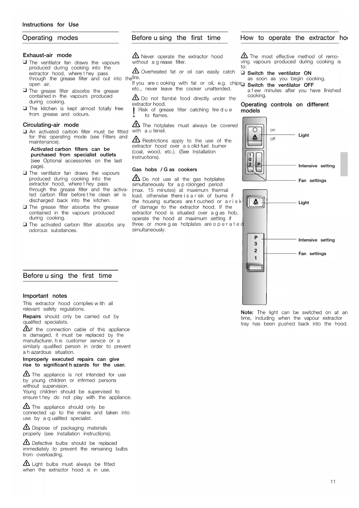
Operating controls on different models
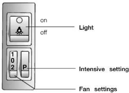
Note: The light can be switched on at an time, including when the vapour extractor tray has been pushed back into the hood.
Before using the first time
Important notes
This extractor hood complies with all relevant safety regulations.
Repairs should only be carried out by qualified specialists.
If the connection cable of this appliance is damaged, it must be replaced by the manufacturer, his customer service or a similarly qualified person in order to prevent a hazardous situation.
Improperly executed repairs can give rise to significant hazards for the user.
The appliance is not intended for use by young children or infirmed persons without supervision. Young children should be supervised to ensure they do not play with the appliance.
The appliance should only be connected up to the mains and taken into use by a qualified specialist.
Dispos of packaging materials properly (see Installation instructions).
Defective bulbs should be replaced immediately to prevent the remaining bulbs from overloading.
Light bulbs must always be fitted when the extractor hood is in use.
Various types of grease filter can be used to absorb the grease contained in the vapours produced during cooking.
Fleece grease filter
The filter mat is made from material that is itself virtually non-inflammable.
Caution:
As it becomes more and more saturated with grease however, the filter becomes increasingly inflammable. The efficiency of the extractor hood can also be adversely affected.
Important:
Renewing the fleece filter at appropriate intervals prevents the possibility of it catching fire as a result of a build-up of heat, such as occurs when deep-fat frying or roasting is taking place.
Renewing the fleece filter:
Under normal operating conditions (1 to 2 hours per day), the fleece filter will require replacing after 8 to 10 weeks. Printed fleece filters must be renewed no later than when the coloured printing has started to fade.
Use only original replacement filters. In so doing you will ensure that safety regulations are upheld and the extractor hood performs as effectively a s possible.
Disposing of the old fleece grease filter:
Fleece grease filters do not contain any pollutants. They can be composted and disposed of as biodegradable waste.
Metal grease filter
The filter mat is made of non-combustible metal.
Caution:
As it becomes more and more saturated with grease, the filter also becomes increasingly inflammable. The efficiency of the extractor hood can also be adversely affected.
Important:
Clean the metal grease filter at regular intervals.
Cleaning the metal filter:
Under normal operating conditions (1 to 2 hours per day), the metal grease filter will require cleaning after 8 to 10 weeks.
The filter can be cleaned in a dishwasher. This can however cause slight discoloration.
Important:
Metal filters that are heavily saturated with grease should not be cleaned at the same time as any crockery, etc.
If the filter mat is going to be cleaned hand, soak it first of all in a hot detergent solution for several hours. Clean the filter with a brush, rinse it off thoroughly and allow it to drip dry.
Use only original replacement filters. In so doing you will be ensuring that the extractor hood performs as effectively as possible.
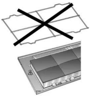
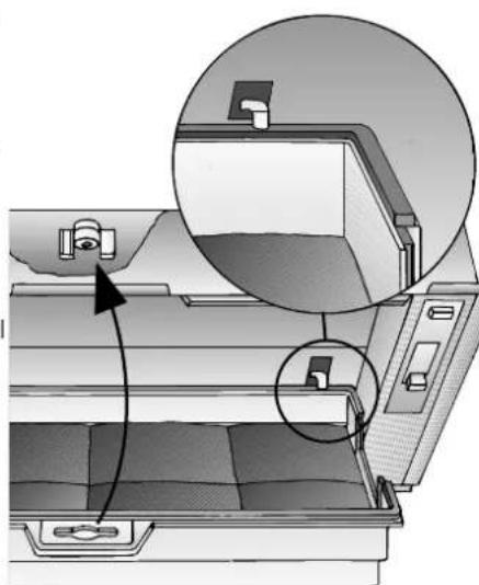
Removing and installing the grease filter
Extractor hoods with a filter mat:
- Rotate the handles on the left and right of the filter grille.
- Press the retaining spring and remove the filter frame.
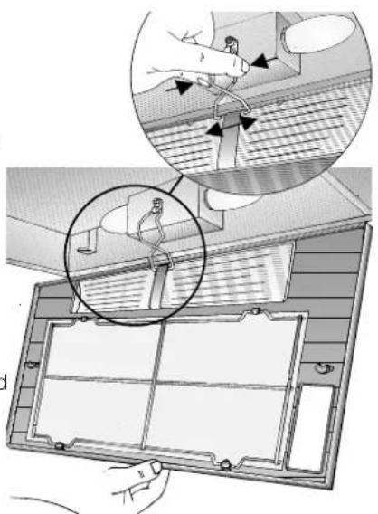
- Remove the wire grille and replace the filter mat.
- Install the filter frame in reverse sequence.
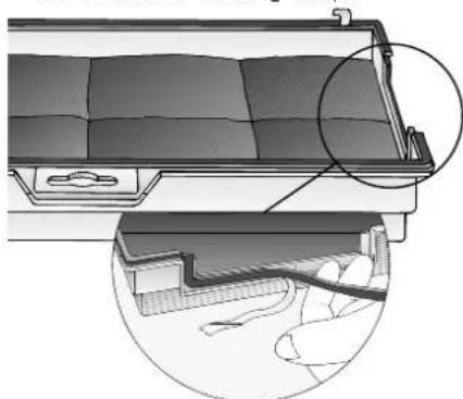
Re-attach the retaining spring.
The left and right sides of the filter frame must lock into position!
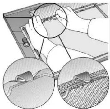
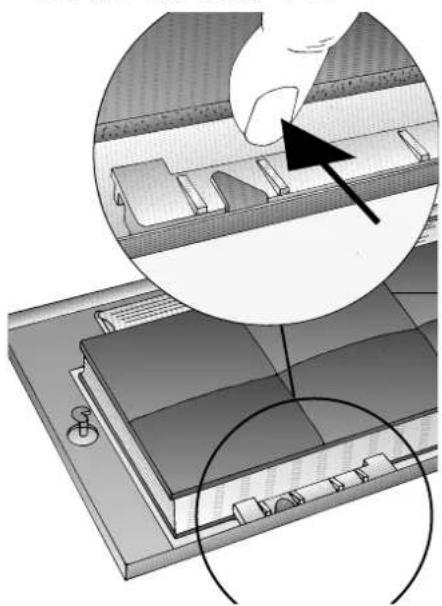
Extractor hoods with two filter cartridges: Warning: The halogen bulbs must be switched off and cool.
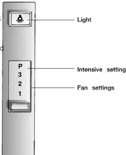
1. Depress the detent on the grease filters in the direction of the arrow and fold down the grease filter slightly. D etach the grease filter by pulling it towards yourself.
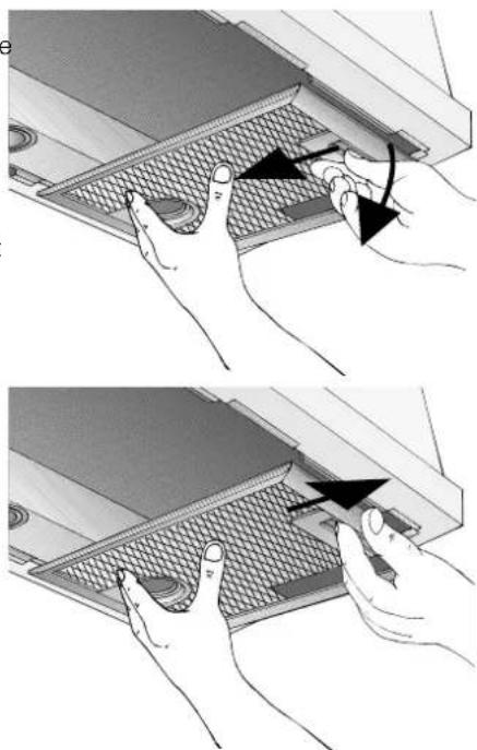
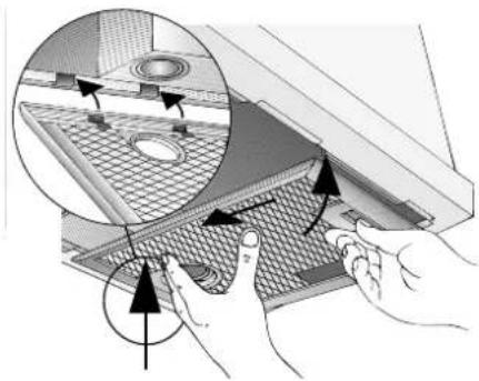
- Clean the grease filters.
- Re-insert the clean grease filters.
Removing and installing the activated carbon filter
Extractor hoods with a filter mat:
- Remove the filter; see grease filter. The wire grille is no longer required when an activated carbon filter is installed.
- Place the activated carbon filter on the filter mat and clamp it in.
- Install the filter frame.
See grease filter.
Extractor hoods with two filter cartridges:
- Remove the filter cartridge. See grease filter.
- Insert the screw through the wing nut and the sleeve and screw in the middle screw in the false bottom (required only during the initial installation). Screw, sleeve and wing nut are enclosed with the activated carbon filter.
- Using a screwdriver, press in the two lugs on the false bottom. If a spacer rail has been installed, it must be removed.
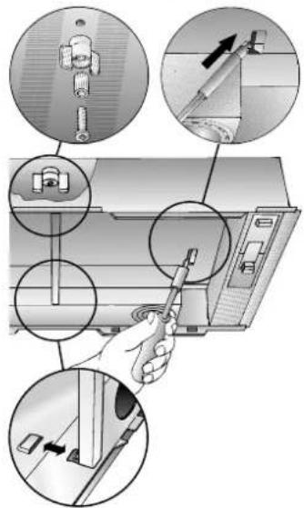
- Tape over the activated carbon filter with the enclosed sealing strip.
- Insert the activated carbon filter at the rear, fold up and lock in the middle with the wing nut. If the spacer rail has been removed, it must be re-installed.
- Re-insert the two filter cartridges.
Removing the activated carbon filter:
The activated carbon filter is removed in reverse sequence.
Changing the activated carbon filter: If used normally (1 to 2 hours daily), the activated carbon filter should be changed approx. once a year.
Activated carbon filters can be purchased from SPECIALIST OUTLETS (see optional accessories on the last page).
Use original filters only. This will ensure optimum performance.
Disposing of the old activated carbon filter:
Activated carbon filters do not contain any pollutants. They can be disposed of e.g. a residual waste.
Switch off the extractor hood and isolate by pulling out the mains plug or switch off the disconnector on the installation side.
At the same time as you renew the grease filter (see Filters and maintenance), clean off any grease from all accessible parts of the housing. This significantly reduces the fire hazard and ensures that the extractor hood performs as effectively as possible.
Clean the extractor hood with a hot detergent solution or a mild window cleaning agent.
If the hood is extremely dirty (older stains), use a liquid window cleaner.
Do not scratch off dried-on dirt, but wipe off with a damp cloth.
Do not use scouring agents.
Warning: Clean the control buttons with a mild detergent solution and a soft, damp cloth only.
Painted, aluminium and plastic surfaces:
- Do not use scouring agents or abrasive sponges.
Do not use dry clothes.
Do not use corrosive, acidic or alkaline cleaning agents.
Note: Do not use alcohol (spirit) on plastic parts, otherwise the surface may become matt in appearance.
Caution! Ensure that the kitchen is adequately ventilated. Avoid naked flames.
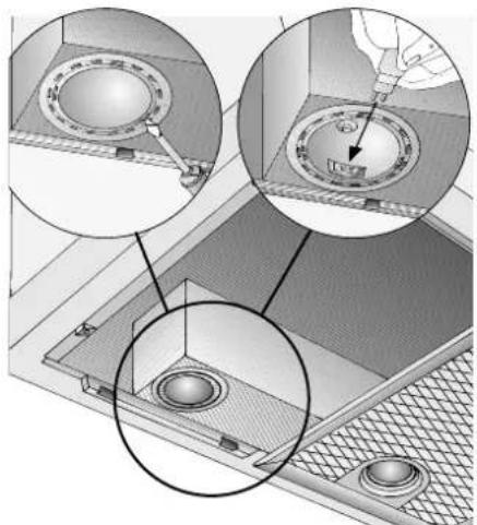
Changing the bulbs
- Switch off the extractor hood and isolat by pulling out the mains plug or switch- ching off the disconnector on the installation side.
- Remove the filter frame. See grease filter.
- Replace the bulb (standard fil a m ent bulb, max 40 W, E14 bulb holder).
- Attach the filter frame. See grease filter.
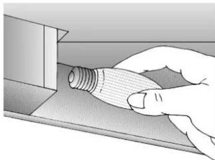
Halogen bulbs:
- Switch off the extractor hood and isolate by pulling out the mains plug or switching off the disconnector on the installation side.
When switched on, the halogen bulbs become very hot. Even for some time after the bulbs have been switched off there is still a risk of burns.
- Remove the bulb ring with a screw or similar tool.
- Replace the halogen light bulb (conventional halogen bulb, 12 Volt, max. 20 Watt, G4 cap). Caution: Refer to for plug-in lampholder.
Take hold of the bulb with a lean clott
- Re-insert the bulb ring.
- Plug the appliance into the mains or switch it on at the fuse box.
Note: If the light does not function, check that the bulbs have been inserted correctly.
If you encounter a problem
If you have any questions or if a fault occurs, please call Customer Service. (See list of Customer Service representatives).
When you call, please quote the following:
| E-Nr. | F | D |
Enter the relevant numbers into the box above. The E-Nr. (product no.) and FD (production date) are shown on the nameplate which can be seen inside the extractor hood after the filter frame has been detached.
Important information
Old appliances are not worthless rubbish. Valuable raw materials can be reclaimed by recycling old appliances. Before disposing of your old appliance, render it unusable.
You received your new appliance in a protective shipping carton. All packaging materials are environmentally friendly and recyclable. Please contribute to a better environment by disposing of packaging materials in an environmentally-friendly manner.
Please ask your dealer or inquire at your local authority about current means of disposal.
The extractor hood can be used in exhaust air or circulating air mode.
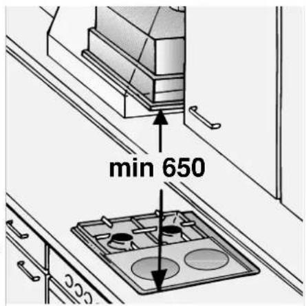
Always mount the extractor hood over the centre of the hob.
Minimum distance between electric hob and bottom edge of extractor hood: 650 mm.
The extractor hood must not be installed over a solid fuel cooker - a potential fire hazard (e.g. flying sparks) - unless the cooker features a closed, non-removable cover and all national regulations are observed.
The smaller the gap between the extractor hood and hotplates, the greater the likelihood that droplets will form on the underside of the extractor hood.
Additional information concerning gas cookers:
When installing gas hotplates, comply with the relevant national statutory regulations (e.g. in Germany: Technische Regel Gasinstallation TRGI).
Always comply with the currently valid regulations and installation instructions supplied by the gas appliance manufacturer.
Only one side of the extractor hood may be installed next to a high-sided unit or high wall. Gap at least 50 mm.
Minimum distance on gas hotplates between the upper edge of the trivet and lower edge of the extractor hood: 650 mm.
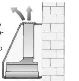
Exhaust-air mode
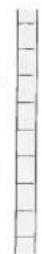
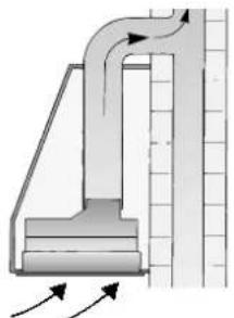
The exhaust air is discharged upwards through a ventilation shaft or directly through the outside wall into the open. Exhaust air should neither be directed into as smoke or exhaust flue that is currently used for other purposes, nor into shaft that is used for ventilating rooms in which stoves or fireplaces are also located.
Local authority regulations must be observed when discharging air into smoke or exhaust flues that are not otherwise in use.
When the extractor hood is operated in exhaust-air mode simultaneously with a different burner which also makes use of the same chimney (such as gas, oil or coal-fired heaters, continuous-flow heaters, hot-water boilers) care must be taken to ensure that there is an adequate supply of fresh air which will be needed by the burner for combustion.
Safe operation is possible provided that the underpressure in the room where the burner is installed does not exceed 4 Pa (0.04 mbar).
This can be achieved if the combustion air can be replenished by being able to flow through non-closeable openings such as in doors, windows, wall ventilation boxes, or by alternative technical measures such as reciprocally shutting the other device off, etc.
An air-intake/exhaust-air wall box by itself is no guarantee that the limiting value will not be exceeded.
Note: When assessing the overall requirement, the combined ventilation system for the entire household must be taken into consideration. This rule does not apply to the use of cooking appliances, such as hobs and ovens.
All legal requirements concerning the discharge of exhaust air must be observed. Unrestricted operation is possible if the extractor hood is used in recirculating mode with activated carbon filter.
The extractor hood should be fitted with a one-way flap for exhaust-air mode if there is not already one installed in the exhaust-air pipe or wall box. If a one-way flap is not enclosed with the appliance, purchase one from a specialist outlet (see optional accessories on the last page).
Attaching the one-way flap
Insert the two lugs on the one-way flap into the holes on the air-pipe connector or air outlet and lock into position.
Before installing the one-way flap, ensure that the lettering or stamp is on the outside.
Optimum performance of the extractor hood:
Short, smooth extraction pipe.
As few pipe bends as possible.
Largest possible pipe diameter (preferably 150 mm) and large pipe bends.
Round pipes:
We recommend for single-motor model, inner diameter of at least 120 mm for double-motor model. inner diameter of at least 150 mm
Flat ducts must have an inner cross-section equivalent to round pipes which have an inner diameter of 120/150 mm.
120 mm ∅ approx. 113²cm
150 mm ∅ approx. 177²cm
If pipe diameters differ: use sealing strip.
Ensure a n a dequate air supply for exhaust-air mode.
Pipe connection
Extractor hoods with 120 mm Ø air outlet:
100 mm extraction pipe
Insert the reducing connector (see optional accessories on the last page) into the air-pipe connector and then attach the exhaust-air pipe.
120 mm Ø extraction pipe
- Attach the exhaust-air pipe directly to the air-pipe connector.
Extractor hoods with 150 mm Ø air outlet:
150 mm extraction pipe
Screw the reducing connector (see optional accessories on the last page) onto the air outlet.
- Attach the extraction pipe to the reducing connector.
150 mm extraction pipe
- Attach the exhaust-air pipe directly to the air outlet.
If a one-way flap has been fitted, conduct a performance test.
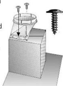
Extractor hoods with rectangular air outlet:
Screw the enclosed air-pipe connector over the air outlet.
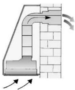
Recirculated air mode
The air cleaned by an additional activated carbon filter is conveyed back into the room.
In recirculated air mode the exhaust opening must be protected by a gr
(see optional accessories on the last page) in order to prevent a mechanical or electrical hazard.
The extractor hood must be connected a correctly installed earthed socket only.
Attach the earthed socket as close to the appliance as possible and in an accessible position. If the earthed socket is no longer accessible following installation of the extractor hood, a disconnector must be provided on the installation side. Disconnectors are switches with a contact opening of more than 3 mm and all-pole disconnection. LS switches and contactors are regarded as disconnectors.
The appliance must be isolated before repairs are carried out.
Repairs may be carried out by authorised technicians only.
If the connection cable of this appliance is damaged, it must be replaced by the manufacturer, his customer service or a similarly qualified person in order to prevent a hazardous situation.
Improper repairs may put the user at considerable risk.
Length of connection cable: 1.20 m.
Electrical specifications:
The electrical specifications can be found on the rating plate inside the appliance when the filter frame has been removed.
Do not place hand in the air outlet.
This appliance complies with the EC radio interference suppression regulations.
The extractor hood is particularly suitable for installation in a flue or chimney.
To ensure optimum extraction performance
(eespecially important for kitchen island solutions):
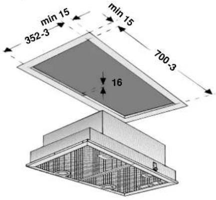
Install the extractor hood as high as possible within the structure
The structure must cover the entire cooking area.
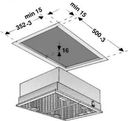
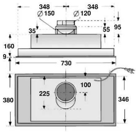
The following cutouts must be made for the installation depending on the model:
Extractor hood with rocker switch, 53 cm wide, 1-motor:
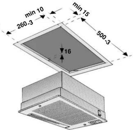
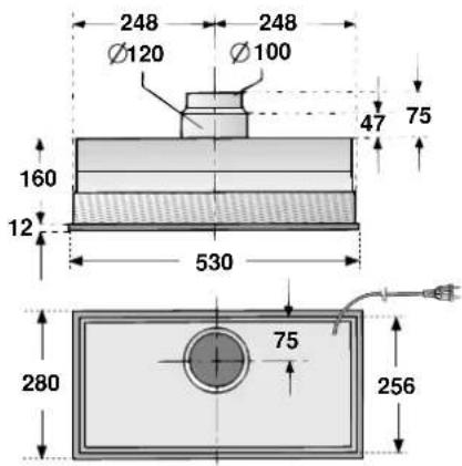
Extractor hood with slide control, 53 cm wide, 1 and 2-motor:
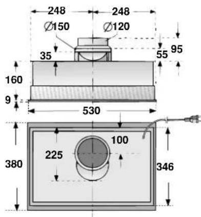
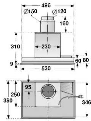
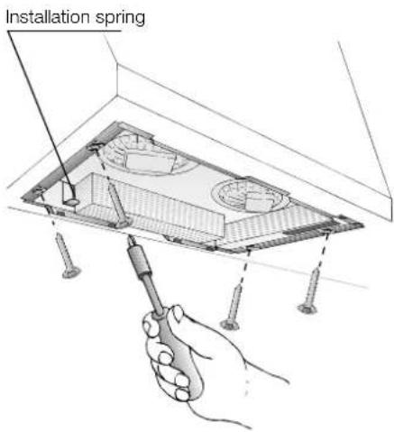
Installation
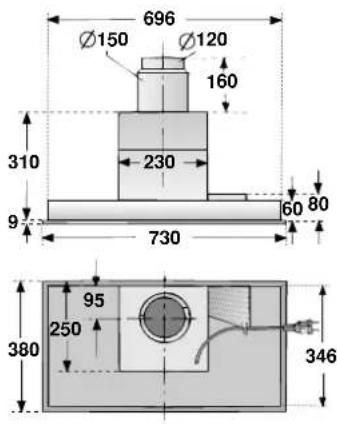
Extractor hood with slide control, 73 cm wide, 1 and 2-motor
- Remove the filter grille (see operating instructions).
- Connect the power.
- Press the extractor hood up into the installation opening until the installation aid locks into position at the front and rear.
- Screw in the extractor hood.
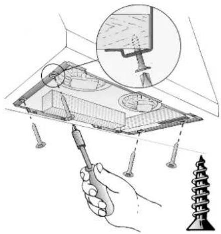
- Insert and secure the filter grille (see operating instructions).
Weight in kg:
| Model | Width | Exhaust air | Recircu lated air |
| 1-motor Rocker switch | 53 cm | 5,0 6 | 3 |
| 1-motor Slide control | 53 cm | 9,5 | 10,7 |
| 1-motor Slide control | 73 cm | 10,3 | 11,6 |
| 2-motor Slide control | 53 cm | 8,3 | 9,5 |
| 2-motor Slide control | 73 cm | 8,7 | 9,9 |
Design changes with respect to technical development shall remain withheld
Removal
- Loosen the screws.
- Hold the underside of the extractor hood, Hold the underside of the extractor hood.
- Lower the extractor hood and remove.
1
m = 311
MeTaaIko pIAtpo AInov
To Tou anotEaI aI aI aI aI aI aI aI aI aI aI aI aI aI aI aI aI aI aI aI aI aI aI aI aI aI aI aI aI aI aI aI aI aI aI aI aI aI aI aI aI aI aI aI aI aI aI aI aI aI aI
Ipooox:
Me tv auon Tou koeou Tou iatpou
ue katao nou triepixouv Aino
aueavetn duvatotnta avapEnc autou
kai npoei va eunodiketai n aeitoupyia
tou anoppopntnpa.
Σημαντικό:
KaqapiZeE Eykaipa To eTaAaiko fIATPO Aiov.
Kaopoioc Tou eTAAIKoI qIATPOIw:
Online-Shop: www.neff-eshop.com