
Gold 200 5G - Speaker MONITOR AUDIO - Free user manual and instructions
Find the device manual for free Gold 200 5G MONITOR AUDIO in PDF.
| Product type | 3-way floorstanding speaker |
| Brand | Monitor Audio |
| Model | Gold 200 5G |
| Frequency response | 35 Hz to 50 kHz (-6 dB) |
| Sensitivity | 88 dB (1 W at 1 m) |
| Nominal impedance | 4 ohms |
| Minimum impedance | 3.4 ohms at 1 kHz |
| Max. sound pressure level | 114 dBA (per pair) |
| Power handling (RMS) | 200 W |
| Recommended amplifier | 80 to 200 W |
| Bass alignment | Dual Bass Reflex HIVE II port |
| Crossover frequencies | 650 Hz (bass/midrange); 3.5 kHz (midrange/tweeter) |
| Driver complement | 2 x 6.5" RDT II (bass), 1 x 2" C-CAM (midrange), 1 x MPD (tweeter) |
| Dimensions (H x W x D) | 950 x 195 x 330.6 mm (with grill and terminals) |
| Dimensions with feet and spikes | 997 x 282.8 x 387.8 mm |
| Unit weight | 21.86 kg |
| Available finishes | Piano black, piano ebony, satin white, dark walnut |
| Main features | Bi-wiring / bi-amping, spike adjustment, port plugs, through-bolt |
| Maintenance and cleaning | Clean with a soft, dry cloth. Do not use liquid or abrasive products. |
| Safety | Check for electrical cables under the carpet before installing spikes. For wall mountings, use appropriate wall plugs. |
| Spare parts and repairability | Contact an authorized Monitor Audio dealer for any repair or spare part. |
| General information | Recommended burn-in of 50 to 70 hours at moderate level. |
Frequently Asked Questions - Gold 200 5G MONITOR AUDIO
User questions about Gold 200 5G MONITOR AUDIO
0 question about this device. Answer the ones you know or ask your own.
Ask a new question about this device
Download the instructions for your Speaker in PDF format for free! Find your manual Gold 200 5G - MONITOR AUDIO and take your electronic device back in hand. On this page are published all the documents necessary for the use of your device. Gold 200 5G by MONITOR AUDIO.
USER MANUAL Gold 200 5G MONITOR AUDIO
For Carpeted Floors 2
For Wooden/ Hard Floors 2
Setting Up 2
2 Channel Positioning 2
AV Positioning 3
Setting up the Gold FX 3
Atmos 4
Fixing the Gold FX to a wall 4
Wiring 5
Single Wiring 5
Bi-Wiring 5
Bi-Amping 5
The Effects of Bi-Wiring and Bi-Amping 6
Portbungs 6
Running-In Your Speakers 7
Retention Bolt Adjustment 7
Warranty 7
Owner Information 7
Specifications 8
Introduction
Monitor Audio's new Gold series of loudspeakers combine premium audio technology with class-leading build quality to deliver a compelling hi-fi and home cinema listening experience. For the first time, the Gold Series features the technology used in Monitor Audio's flagship Platinum II series to deliver a pure high-end performance.
The Monitor Audio team have used their years of audio design experience to reduce distortion in the Gold Series to an absolute minimum, and to ensure the sound delivered is as clear and articulate as possible, whilst being smooth and easy on the ear. The new Gold speakers represent a full redesign and the drivers used in the Platinum series have been especially re-developed, honed and refined.
A single bookshelf model, two floor-standers, single centre speaker, subwoofer and rear/ FX speakers completes the new range. The Gold series is designed for the demanding listener looking for speakers with high-end credentials and a stunning appearance.
The beautifully designed cabinets are available in dark walnut and ebony real wood veneer plus piano gloss black or satin white finishes. The rounded vertical edges of the cabinets combine with the sharp profile of the horizontal lines to give a classic and timeless appearance. A leather soft touch top panel trim (on the bookshelf and floor standing speakers) is soft to the touch and adds a further premium appeal to the Gold series. All cabinets are heavy and well damped with extensive bracing, augmented by Monitor Audio's renowned single bolt through drivers that allow a pure appearance.
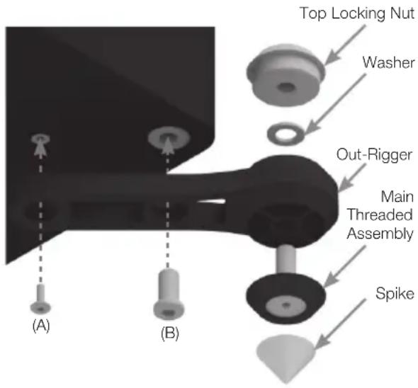
For Carpeted Floors
(Gold 200 and 300 only)
The feet and 'out-riggers' are supplied assembled for use on carpeted floors or where spikes are appropriate. All that is required is to fix them to the speaker base using the supplied bolts (A & B).
You can check that the speaker is level on all sides by using the spirit level. If it's slightly off-level, unscrew the foot at the lowest point and check again. Continue this process until the cabinet is fully level. Use the locking nuts on each foot to fix the feet in place and to stop any unwanted vibrations.
Please ensure there are no hidden wires under the carpet that could be damaged by the spikes.
For Wooden/ Hard Floors
(Gold 200 and 300 only)
Remove the spikes and fix the feet and 'out-riggers' to the speaker base using the supplied bolts (A & B).
You can check that the speaker is level on all sides by using a spirit level. If it's slightly off-level, unscrew the foot at the lowest point and check again. Continue this process until the cabinet is fully level. Use the locking nuts on each foot to fix the feet in place and to stop any unwanted vibrations.
Setting Up
2 Channel Positioning
When arranging a 2 channel system, the listening position and the loudspeakers should form an equilateral triangle. The speakers should be positioned approximately 6 - 10 feet (1.8 - 3m) apart. The ideal distance from the rear wall varies depending on the speaker (see list below), however, for optimal performance they need to be a minimum of 3 feet (91cm) from the side walls.
Gold 100 8-14 inches (20 - 35cm)
Gold 200 and Gold 300 12 - 18 inches (30 - 45cm)

NOTE: These are recommended distances for optimal performance. Actual results will vary dependant on room size and construction.
Experimentation is strongly advised when initially setting up the speakers, as environment and personal preference differ with every installation. If there is insufficient bass for example, try moving your speakers closer to a wall. The opposite approach is recommended if there is excess bass. Also see the information in the Port Bungs section. If stereo imaging is being lost, try 'toeing' them in slightly. The sound should appear to originate from the centre point between the speakers, not the actual speakers themselves.
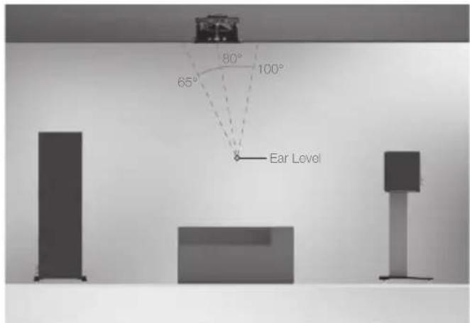
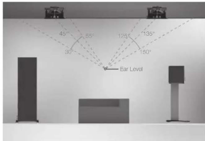
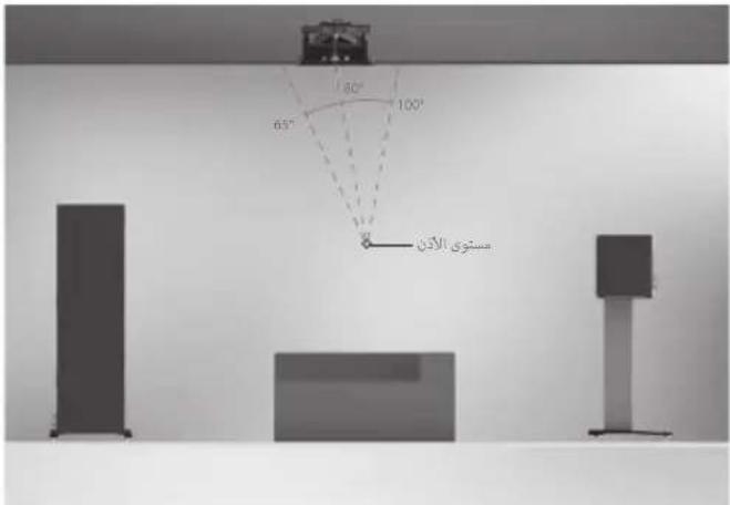
AV Positioning
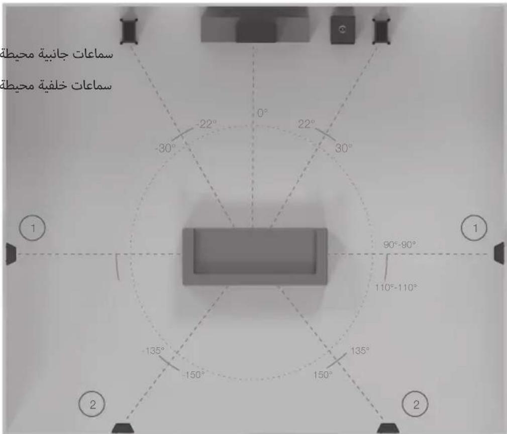
Please refer to the illustrations below for the ideal angles and positions of each speaker in your surround system. The speakers should be distanced from the wall according to the requirements of the speaker, which are listed in the 2-Channel Positioning section.
If the sound is too bass heavy or there is bass boom from the room when playing music (without a subwoofer), try moving the loudspeakers slightly further away from the wall(s). If this is not possible, then try the supplied port bungs. In a system with a subwoofer try adjusting the crossover frequency settings for the speakers and/or sub or changing the subwoofer's position.
The Gold C250 centre speaker should be positioned so that it is pointing at approximate ear height of the main listening position. Included with the C250 are 4 adhesive feet, stick these to the bottom of the cabinet for protection and to help isolate the speaker.

NOTE: Images below are for illustrative purposes only. If using the Gold FX please refer to the 'Setting Up the Gold FX' section for further information.
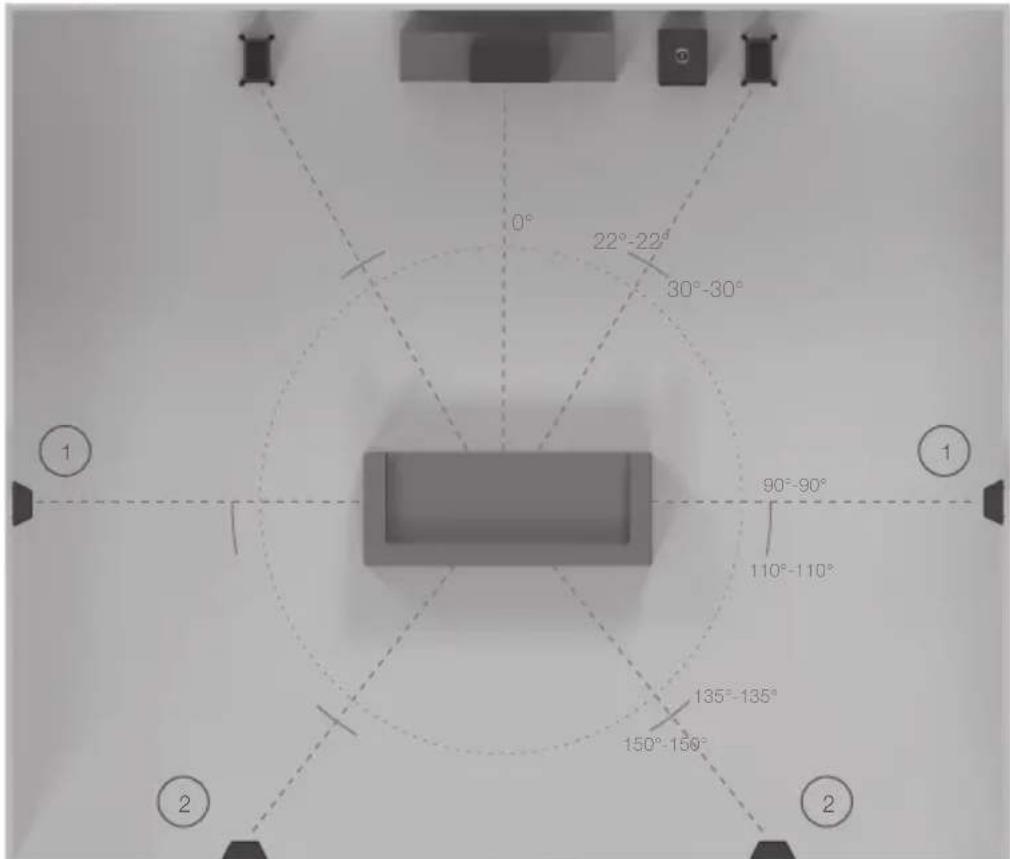
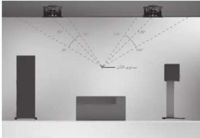
- Side surround speakers
- Rear surround speakers
A 7.1 surround system will make use of side (position 1) and rear speakers (position 2). If setting up a 5.1 system you can place your surrounds in position (1) or (2).
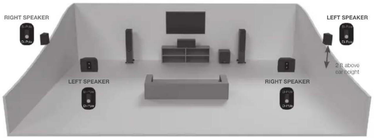
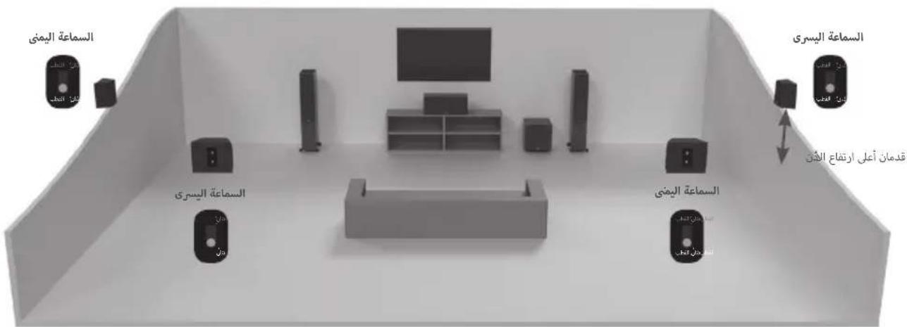
Setting up the Gold FX
The Gold FX features Di-Pole or Bi-Pole listening modes. In Bi-Pole mode, both drivers and tweeters are all in phase. In Di-Pole mode the tweeters and drivers on one side of the speaker is out of phase to the other tweeter and driver to create the diffused sound. The FX speakers should be wall mounted approximately 2 feet above ear height.
Di-Pole/ Bi-Pole switch: When part of 5.1 systems as a rear speaker, set the switch to Bi-Pole. Although there is nothing wrong with experimenting and trying the switch in the Di-Pole mode.
If part of a 7.1 system with 1 pair of FX's set the switch to Di-Pole. If using 2 pairs of FX's for side and rear effects, set them all to Di-Pole mode and swap the left and right handed side FX speakers over, keeping the rear FX speakers handed correctly (matching left and right with the front left and right channels) as illustrated on the next page.

NOTE: Before adjusting any switches, please ensure that the amplifier is at the very least turned off. This will help to protect the amplifier.
Atmos
When arranging an Atmos system, or the overhead channels in an Atmos system we would recommend using our C265-IDC, C380-IDC or CPCT380-IDC. These speakers employ a unique pivoting IDC (Inverted Dual Concentric) midrange/tweeter module which offers a wider dispersion characteristic, and is ideal for Atmos duties. More information on the C265-IDC, C380-IDC and CPCT380-IDC can be found on our website: monitoraudio.com
Please see below for ideal positioning of 2 or 4 Atmos speaker setups.
2 Atmos speakers (in line with front left and right) 4 Atmos Speakers (in line with front left and right)
Fixing the Gold FX to a wall

CAUTION: Always determine where the Gold FX will be fixed and the structure of the wall. For safety reasons, if unsure of your ability to provide a secure and safe fixing, do not attempt to fix these speakers to a wall. Instead, please obtain the services of a competent and qualified trades person.

CAUTION: Ensure that water pipes or electricity cables do not run behind where the wall plate is going to be secured. Work from secure steps and avoid trailing wires.

NOTE: We do not supply wall fixing screws and plugs with the Gold FX. Please only use suitable fixings for the type of wall construction the Gold FX's will be fixed to.
The Gold FX comes with keyhole inserts for use with the included wall bracket. We do not supply wall fixing screws and plugs with the FX's to fix the bracket to the wall. Please use suitable fixings for the type of wall construction the FX's will be fixed to.
To fix your FX's to the wall, we would recommend using the wall fixing template enclosed within the packaging carton.
Wiring
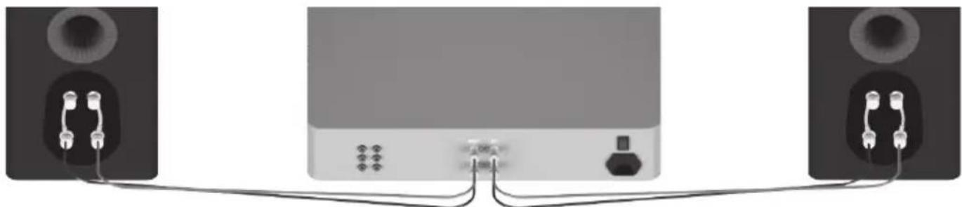
Single Wiring
Single wiring is achieved via a single set of cables to the terminals on the back of the loudspeaker. Internally the loudspeaker crossover guides the frequencies to the appropriate driver/tweeter. Low frequencies to the bass drivers, mid frequencies to the mid/bass drivers and high frequencies to the tweeter.
It is perfectly acceptable to connect to the top, bottom terminals or even diagonally (experimentation is advisable to achieve the preferred results).
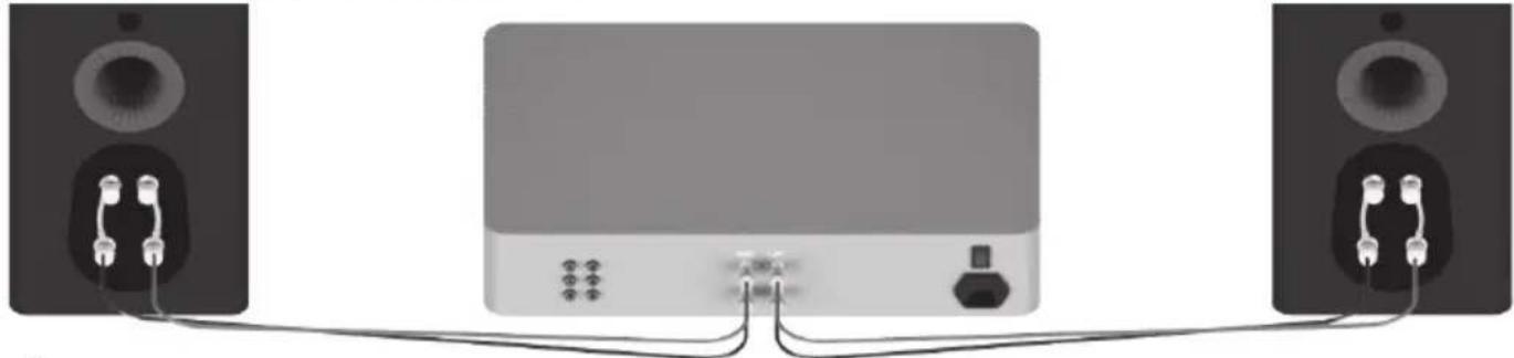

NOTE: When using this method you must keep the terminal links in place.
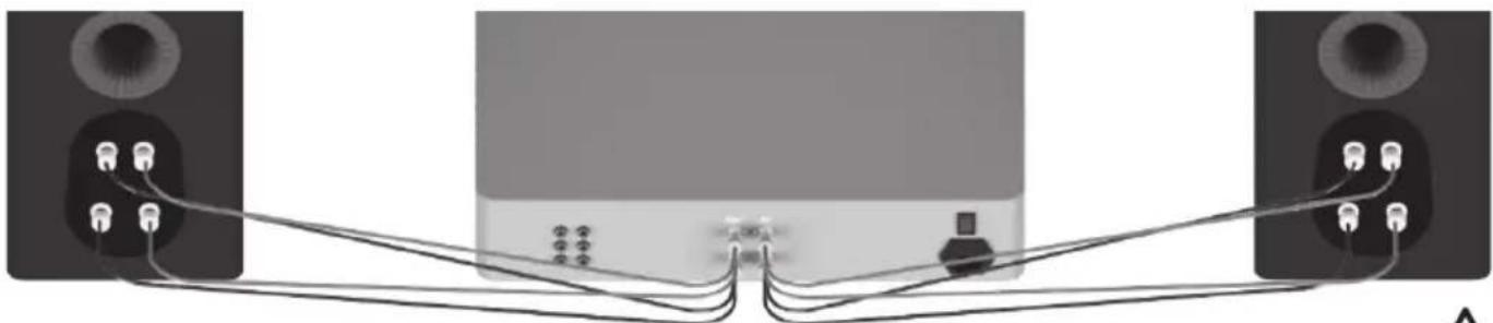
Bi-Wiring
Bi-wiring is accomplished by connecting separate pairs of speaker cables to the terminals on the loudspeaker from a single pair of connections on the amplifier. In the case of the Gold Series, the bottom terminals connect to the bass driver(s) and the top terminals connect to the tweeter in 2 way loudspeakers, or the mid and tweeter in 2.5 and 3 way loudspeakers.
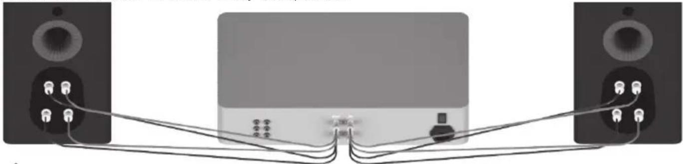

NOTE: When using this method the terminal links MUST be removed.
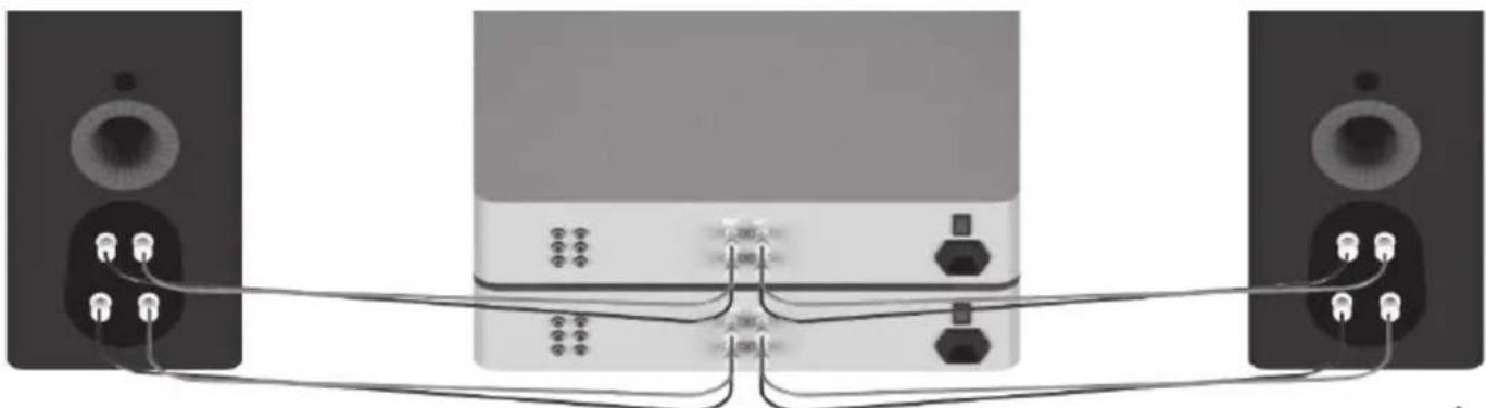
Bi-Amping
Bi-amping is the same as bi-wiring except you are introducing a second amplifier into the equation.
In order to bi-amp you must connect a set of speaker cables to the top terminals on the loudspeaker from one amplifier and another set of speaker cables to the bottom terminals from the second amplifier.

NOTE: When wiring this method the terminal links MUST be removed.
The Effects of Bi-Wiring and Bi-Amping
Fundamentally a loudspeaker crossover varies the impedance seen by the speaker and by the power amplifier. When a full range audio signal is applied to the terminals of a full range speaker system, the bass driver(s) will only receive low frequency signals, the mid driver receives the mid band frequency signals and the tweeter only gets sent high frequency signals.
This means that if separate speaker cables are connected to the low and high frequency terminals, not only have the drive units had the frequency's directed and divided for them, but if using a bi-wire setup the two separate speaker cables will now also carry different signals due to the impedance. So the bass cables carry mostly the low frequencies, and the tweeter cable mostly the highs.
The effects of bi-wiring are subtle and depending on the cable construction and design it could be better to go for one better engineered cable than two for bi-wiring. Monitor Audio recommends experimenting with both configurations to find out which one works best in your system.
Bi-amping adds an additional amplifier to the system so that the one amplifier drives the low frequencies and the other amplifier drives the high frequencies. Bi-amping can therefore present a 'cleaner' signal at both the low frequency and high frequency speaker terminals, and because the high and low frequencies have already been separated, each has a minimal effect on the other - in essence the bass has less effect on the delicate treble. In order to best take advantage of bi-amping the amplifiers should be as independent from each other as possible. For instance, if using two stereo amplifiers you should use one stereo amplifier for the bass and the other for the treble, minimising the impact of the bass on the treble.
Port bungs

WARNING: Care must be taken not to insert the port bungs too far into the port, as this may result in the foam bung being lost inside the cabinet.
If the loudspeaker is to be installed in a small room, typically 9 sqM (80 sqFT), or a room known to reproduce accentuated bass response, it may be desirable to fit port bungs. However, experimentation is recommended with positioning of the loudspeaker in the room prior to fitting. To optimise performance from the loudspeaker it is important to ensure the loudspeaker is not positioned too close to a wall or near the corners of a room.
If the positioning of the loudspeaker is predetermined by room aesthetics or layout, you find you have accentuated bass or in the case speakers are to be sited in close proximity (less than the minimum suggested distances shown in the 2 Channel Positioning section) to a rear wall (such as on a bookshelf, positioned in a cabinet or on a stand close to a wall), we recommend fitting port bungs to the ports. This will reduce the bass 'boom' sometimes termed as overhang, and assist the loudspeakers to reproduce their best performance under these environmental conditions. 'Boom' is generally caused when bass energy from the loudspeaker 'excites' room modes and causes an accentuation at a particular frequency, or number of frequencies.
When fitting port bungs the overall bass extension will not be reduced, however bass energy/ output around the port tuning frequency will be reduced. This has the effect of reducing bass 'boom' while increasing bass clarity and apparent agility.
In all circumstances experimentation is highly recommended.
Running-In Your Speakers
Run your speakers in by playing normal music at low-mid listening levels for approximately 50-70 hours play time. You may find the sound will continue to improve even after the 70 hour mark.
This can be done naturally over time: like a fine wine the performance will improve with age.
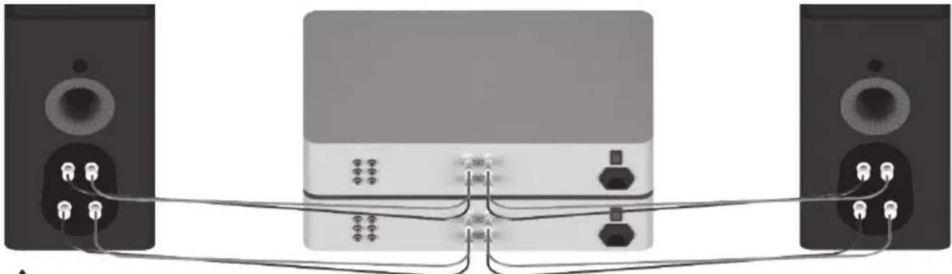
Alternatively if you wish to run the speakers continuously on loop you can decrease the audible volume/ presence by placing the speakers face-to-face so that the drivers/tweeters are directly aligned and as close as possible. Then connect the amplifier to your speakers so that one is as normal (in phase): positive to positive and negative to negative (red to red and black to black), and the other speaker out of phase: positive to negative and negative to positive inputs on the speaker.
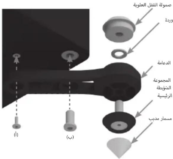
Retention Bolt Adjustment
The new Gold Series has a bolt-through driver fixing to reduce cabinet colouration. Each bolt acts as a rigid brace, but also removes the need for conventional driver fixings as well, effectively decoupling the driver and front baffle to eliminate a further source of resonance.

NOTE: Should this bolt become loose over time, or has worked loose during transit, then please use the supplied hex key to tighten the bolt back up. This only needs to be a quarter turn after the strain has been taken by the bolt.
Warranty
Both the craftsmanship and the performance of this product is covered by the manufacturer's warranty against manufacturing defects provided that the product was supplied by an authorised Monitor Audio retailer under the consumer sale agreement. For the period of cover please refer to the product page on our website: monitoraudio.com for the product you have purchased.
When purchasing Monitor Audio products, please keep your receipt of purchase safe, as this validates your warranty.
Owner Information
Product Details
Model:
Product Serial No:
Date of Purchase:
Dealer Details
Dealer Name:
Address:
Post code:
E-mail address:
Specifications
| MODEL Gold 100 Gold 200 Gold 300 Gold C250 Gold FX | |||||
| System Format | 2-way 3-way 3-way 3-way 2-way | ||||
| Frequency Response (-6dB) | 40 Hz - 50 kHz 35 Hz - 50 kHz 30 Hz -50 kHz 40 Hz -50 kHz 60 Hz -50 kHz | ||||
| Sensitivity (1W@1M) | 86 dB 88 dB 90 dB 88 dB 86 dB | ||||
| Nominal Impedance | 4 Ohms 4 Ohms 4 Ohms 4 Ohms | 4 Ohms | |||
| Minimum Impedance | 2.8 Ohms @ 3.4 kHz | 3.4 Ohms @ 1 kHz | 3.5 Ohms @ 1 kHz | ||
| Maximum SPL | 110 dBA (Pair) | 117 dBA (Pair) | 117 dBA (Each) | ||
| Power Handling (RMS) | 120 W 200 W | 250 W | 200 W 100 W | ||
| Recommended Amplifier Requirements | 60 - 120 W | 80 - 200 W | 100 - 250 W | ||
| Bass Alignment | Bass reflex H/He II port system | Bass Reflex Dual H/He II port system | Bass Reflex Dual H/He II port system | ||
| Crossover Frequency | 2.5 kHz | L.F/ M.F: 650 Hz M.F/ H.F: 3.5 kHz | L.F/ M.F: 650 Hz M.F/ H.F: 2 kHz | ||
| Drive Unit Complement | 1 x 6" RDT II long-throw bass driver 1 x MPD high frequency transducer | 2 x 6" RDT II long-throw bass drivers 1 x 2" C-CAM mid-range driver 1 x MPD high frequency transducer | 2 x 6" RDT II long-throw bass drivers 1 x 2" C-CAM mid-range driver 1 x MPD high frequency transducer | ||
| External Dimensions Including Grilli and Terminals (H x W x D) | 360 x 195 x 330.6 mm 14" x 7" x 13" | 950 x 195 x 330.6 mm 37" x 7" x 13" | 1000 x 240 x 360.6 mm 39" x 9" x 14" | ||
| External Dimensions Including Outrigger Feet and Spikes (H x W x D) | N/A | 997 x 282.8 x 387.8 mm 39" x 11" x 15" | 1047 x 327.8 x 417.8 mm 41" x 12" x 16" | ||
| Weight (Each) | 9.12 kg 20 lb 2 oz | 21.86 kg 48 lb 2 oz | 30.56 kg 67 lb 4 oz | ||
| Finishes | Piano Black, Piano Ebony, Satin white, Dark Walnut | ||||
Monitor Audio reserves the right to alter specifications without notice.
Table des matieres
Introduction 9
Pointes et pieds 10
Monitor Audio reserves the right to alter specifications without notice.
Copepknne
Iglll llllllllllllllllllllllllllllllllllllllllllllllllllllllllllllllllllllllllllllllllllllllllllllllllllllllllllllllllllllllllllllllllllllllllllllllllllll
Monitor Audio
Gld 1g 1 g 1 g 1 g 1 g 1 g 1 g 1 g 1 g 1 g 1 g 1 g 1 g 1 g 1 g 1 g 1 g 1 g 1 g 1 g 1 g 1 g 1 g 1 g 1 g 1 g 1 g 1 g 1 g 1 g 1 g 1 g 1 g 1 g
J 1
Oclawg oog aag g yjy aclawg ayly b jg klll jgljg jdyd jdg
gagog ojgbocu cukoy gao jll cclawl jc agb jky jnnnnaaoll aaa Gold alawg.FX claw / a
a a a a a a a a a a a a a a a a a a a a a a a a a a a a a a a a
aag. jyj y 15 kss kgs aagb bgsal l gaa aagll aajl alggl aagw g
a a 1000000000000000000000000000000000000000000000
aaii jg jol g jao ojzso lgl os 1 aokall acll Jks j01 1 gclzo Jzso bao ao g alao slall g. Gold
Lalls Iabe oohcMonitor Audio
Jy Jy
(baa 300g Gold 200 |j|yb)
g o jy lo jg. dawlio rolwlln gglj glj wylly aogwrll lgl 0dss sasao "clolc"g alddll gla
.()jlaalllolduwlydcllld
s 1
oogoljaoolgoouxul. lolo gno goggudall yoo aolll oio g jaioi .sfo gao agaboi sdi oia
.1g 1
.
A/
(ba3 300g Gold 200 |jlyb)
jlll lalld aclll oclg 1olccg olalolall
.
goo ool olduw yolgl gag aig uo aclawl n o gaoall kai abu jue ooll aga aol ao 150 .dgu w guo gog g ouuul cag aol oio g rsw. s rjfo gao gao gok
g
[ \downarrow \left( {x,y}\right) ]
gai li gol
gagolgo gclalglgogbgygol yglalglgolgoglaalglgogjy jy alalal 10-6 10
.3 1 1 1 1 1 1 1 1 1 1 1 1 1 1 1 1 1
(ω35-20) ωg y 14-8
Gold 100 jIb
(ω45-30) ωg 18-12
Gold 3009 Gold 200
.1a111 1

g 1 g 1 g 1 g 1 g 1 g 1 g 1 g 1 g 1 g 1 g 1 g 1 g 1 g 1 g 1 g 1 g 1 g 1 g 1 g 1 g 1 g 1 g 1 g 1 g 1 g 1 g 1 g 1 g 1 g 1 g 1 g 1 g 1 g 1 g
aaii aiee iiaeaai 10000000000000000000000000000000000000
Jcclaw Jlalllg 1g 1g jg jg jg jg jg jg jg jg jg jg jg jg jg jg jg jg jg jg jg jg jg jg jg jg jg jg jg jg jg jg jg jg jg jg jg jg jg jg jg
((g)aagg)gaggall jiaaa uic aafjlln no dargall gajg jdgglgglgglgglgglgglgglgglgglgglgglgglgglgglgglgglgglgglgglgglgglgglgglgglgglgglgglgglgglgglgglgglgglgglgglgglgglgglgglgglgglgglgglgglgglgglgglgglgglgglggl
C250 g o n aag .g y g g g g g g g g g g g g g g g g g g g g g g g g g g g g g g g g g g g g g g
Gold duc" aal l jy Gdf FX alxw alg g. baf aaggul fag U aill oogall s:ab>lo .tloglall no yj zo JgaoJ "FX

7.1 b20all 11
(1 g0gll) aalgl lclal
a1lgl.(2 g0gll) aalgl
a0blg .5.1 albi
.(2) (1) g0gll
Gold FX
g g g g g g g g g g g g g g g g g g g g g g g g g g g g g g g g g g g g g g g g g g g
a 5.1 a b 5i j 5 i
claw no jgjolldw dic. boll ggl fX cIclaw no gjolldw 7.1 o jn no e jbdo xie
blallgo gllf FX cIclaw no jn bllbllg glg boll gglg lglg bllg aiaa aiaa Jx
,dlallaeall (aoloal yllgaiyllgaiyllgaiyllgaiyllgaiyllgaiyllgaiyllgaiyllgaiyllgaiyll
.

Atoms
J .CPCT380-IDC g C380-IDC g C265-IDC ,Atmos , j Atoms , j Atoms , j Atoms , j Atoms , j Atoms , j Atoms , j Atoms , j Atoms , j Atoms , j Atoms , j Atoms , j Atoms , j Atoms , j Atoms , j Atoms , j Atoms , j Atoms , j Atoms , j Atoms , j Atoms , j Atoms , j Atoms , j Atoms , j Atoms , j Atoms , j Atom s, j Atoms, j Atoms, j Atoms, j Atoms, j Atoms, j Atoms, j Atoms, j Atoms, j Atoms, j Atoms, j Atoms, j Atoms, j Atoms, j Atoms, j Atoms, j Atoms, j Atoms, j Atoms, j Atoms, j Atoms, j Atoms, j Atoms, j Atoms, j Atoms, j Atoms, j Atom s, JAtom s, JAtom s, JAtom s, JAtom s, JAtom s, JAtom s, JAtom s, JAtom s, JAtom s, JAtom s, JAtom s, JAtom s, JAtom s, JAtom s, JAtom s, JAtom s, JAtom s, JAtom s, JAtom s, JAtom s, J
monitororaudio.com
Atmos cllaw no cllaw 4 g! nclaw lal y llalg
(gssallaaiaa)Atmos lclaw(
Jg s Jg Jg)Atmos 4
bjol金 Gold FX jng C
Jgog c0s fcld y jy Jgl 00 g
a 1
.
Jg j 1000000000000000000000000000000000000000000000000000000000000
Laed Gd Fx jby oJbJl


jIb g o 1d lalw g bllg 8 100. 4e 1000000000000000000000000000000000000000000000000000000
.
.
JxwJU
JxJ1 Jg
y
Jgollllgljrgd/abwgoollxlaa 1 abwgooll
()JloKg>glddjllaaeaegeaegalpblgagallolao
LgKo 3 aRbI cXogJcBlaQaOa oia ploaiu iic:abx

JxwJ Loo
J 1 1 1 1 1 1 1 1 1 1 1 1 1 1 1 1 1 1 1 1 1 1 1 1 1 1 1 1 1 1 1 1 1 1 1 1 1 1 1 1 1
aBbI xlogI aIj! cAaBbIO oio pUauu uic: aboXo

Jn 26 JxJ1 Joo
a
.1111111111111111111111111111
aBbll cIwogll aIjI yabbl oIgI wOJI uOgI uO

monitororaudio.com 85
aIgblglbllalok gog oJgag aclawl lglglaall jg bglalc yw alg 1
.aa 23
gaaagaaagaaagaaagaaagaaagaaagaaagaaagaaagaaagaaagaaagaaagaaagaaagaaagaaagaaagaaagaaagaaagaaagaaagaaagaaagaaagaaagaaagaaagaaagaaagaaagaaagaaagaaagaaagaaagaaagaaagaaagaaagaaagaaagaaagaaagaaagaaagaaagaaagaa
.
.1J 1 J 1 J 1 J 1 J 1 J 1 J 1 J 1 J 1 J 1 J 1 J 1 J 1 J 1 J 1 J 1 J 1 J 1 J 1 J 1 J 1 J 1 J 1 J 1 J 1 J 1 J 1 J 1 J 1 J 1 J 1 J 1 J 1 J 1 J
g g a aiaaaii i 1 1 1 1 1 1 1 1 1 1 1 1 1 1 1 1 1 1 1 1 1 1 1 1 1 1 1 1 1 1 1 1 1 1 1 1 1 1 1 1 1 1 1 1 1 1 1 1 1 1
1 1
islibl 101
dssssssssssssssssssssssssssssssssssssssssssssssssssssssssssssssssssssssssssssssssssssss
.

gac aJyLd 1234567890101123456789010112345678901011234567890101123456789010112345678901011234567890101123456789010112345678
aJn jn Jn Jn Jn Jn Jn Jn Jn Jn Jn Jn Jn Jn Jn Jn Jn Jn Jn Jn Jn Jn Jn Jn Jn Jn Jn Jn Jn Jn Jn Jn Jn Jn Jn
Jg 1 g 1 g 1 g 1 g 1 g 1 g 1 g 1 g 1 g 1 g 1 g 1 g 1 g 1 g 1 g 1 g 1 g 1 g 1 g 1 g 1 g 1 g 1 g 1 g 1 g 1 g 1 g 1 g 1 g 1 g 1 g 1 g 1 g 1 g
.1 1 1 1 1 1 1 1 1 1 1 1 1 1 1 1 1 1 1 1 1 1
1g. j 1000000000000000000000000000000000000000000
gog jyjoc gaoaall gaaol sgaiao aaiy jaiyagai jaiyaiyaiyaiyaiyaiyaiyaiyaiyaiyaiyaiyaiyaiyaiyaiyaiyaiyaiyaiyaiyaiyaiyaiyaiyaiyaiyaiyaiyaiyaiyaiyaiyaiyaiyaiyaiyaiyaiyaiyaiyaiyaiyaiyaiyai
ccllalwly gall joo. Jko yj d a jg o jolal/ kai wll olldo aeg l g
gogll jgl gjll aclawlg (gwl ydl gwl gwl jywl jywl) wlll wlwl lg gall: gol
.
jIiJyI JIeWo bwo
Juslll lss s Jy jy a 1s, a ooc Jaao Jg Jg Gld aalw
| Gold FX Gold C250 Gold 300 Gold 200 Gold 100 | العربية الحرفية الحرفية الحرفية الحرفية الحرفية الحرفية الحرفية الحرفية الحرفية الحرفية الحرفية الحرفية الحرفية الحرفية الحرفية الحرفية الحرفية الحرفية الحرفية الحرفية الحرفية الحرفية الحرفية الحرفية الح註冊 العربية الحرفية الح註冊 العيلة الح註冊 العيلة الح註冊 العيلة الح註冊 العيلة الح註冊 العيلة EXCELLENTLY | العربية EXCELLENTLY | العيلة EXCELLENTLY | العيلة EXCELLENTLY | العيلة EXCELLENTLY |
| العيلة EXCELLENTLY | العيلة EXCELLENTLY | العيلة EXCELLENTLY | العيلة EXCELLENTLY | العيلة EXCELLENTLY | العيلة EXCELLENTLY |
| العيلة EXCELLENTLY | العيلة EXCELLENTLY | العيلة EXCELLENTLY | العيلة EXCELLENTLY | العيلة EXCELLENTLY | العيلة EXCELLENTLY |
| العيلة EXCELLENTLY | |||||
| العيلة EXCELLENTLY | |||||
| العيلة EXCELLENTLY | |||||
| العيلة EXCELLENTLY | |||||
| العيلة EXCELLENTLY | |||||
| العيلة EXCELLENTLY | |||||
| العيلة EXCELLENTLY | |||||
| THESE | THESE | THESE | THESE | THESE | THESE |
| THESE | THESE | THESE | THESE | THESE | THESE |
| THESE | THESE | THESE | THESE | THESE | THESE |
| THESE | THESE | THESE | THESE | THESE | THESE |
| THESE | THESE | THESE | THESE | THESE | THESE |
| THESE | THESE | THESE | THESE | THESE | THES |
| THESE | THESE | THESE | THESE | THESE | THES |
| THESE | THESE | THESE | THESE | THESE | THES |
| THESE | THESE | THESE | THESE | THESE | THES |
| THESE | THESE | THESE | THESE | THESE | THES |
| THESE | THESE | THESE | THESE | THESE | THEs |
| THESE | THESE | THESE | THESE | THESE | THES |
| THESE | THESE | THESE | THESE | THESE | THES |
| THESE | THESE | THESE | THESE | THESE | THES |
| THESE | THESE | THESE | THESE | THESE | THES |
| THESE | THESE | THESE | THESE | THESE | THET |
| THESE | THESE | THESE | THESE | THESE | THES |
| THESE | THESE | THESE | THESE | THESE | THES |
| THESE | THESE | THESE | THESE | THESE | THES |
| THESE | THESE | THESE | THESE | THESE | THES |
| THESE | THESE | THESE | THESE | THESE | THEt |
| THESE | THESE | THESE | THESE | THESE | THES |
| THESE | THESE | THESE | THESE | THESE | THES |
| THESE | THESE | THESE | THESE | THESE | THES |
| THESE | THESE | THESE | THESE | THESE | THES |
| THESE | THESE | THESE | THESE | THESE | THE S |
| THESE | THESE | THESE | THESE | THESE | THES |
| THESE | THESE | THESE | THESE | THESE | THES |
| THESE | THESE | THESE | THESE | THESE | THES |
| THESE | THESE | THESE | THESE | THESE | THES |
| THESE | THESE | THESE | THESE | THESE | THE T |
| THESE | THESE | THESE | THESE | THESE | THE S |
| THESE | THESE | THESE | THESE | THESE | THES |
| THESE | THESE | THESE | THESE | THESE | THE S |
| THESE | THESE | THESE | THESE | THESE | THE S |
| THESE | THESE | THESE | THESE | THESE | THE S |
| THESE | THESE | THESE | THESE | THESE | THE S |
| THESE | THESE | THESE | THESE | THESE | THE S |
| THESE | THESE | THESE | THESE | THESE | THES |
| THESE | THESE | THESE | THESE | THESE | THE S |
| THESE | THESE | THESE | THESE | THESE | THE S |
| THESE | THESE | THESE | THESE | THESE | THES |
| THESE | THESE | THESE | THESE | THESE | THE S |
| THESE | THESE | THESE | THESE | THESE | THES |
| THESE | THESE | THESE | THESE | THESE | THE S |
| THESE | THESE | THESE | THESE | THESE | THE S |
| THESE | THESE | THESE | THESE | THESE | THE s |
| THESE | THESE | THESE | THESE | THESE | THE S |
| THESE | THESE | THESE | THESE | THESE | THE S |
| THESE | THESE | THESE | THESE | THESE | THE S |
| THESE | THESE | THESE | THESE | THESE | THE S |
| THESE | THESE | THESE | THESE | THESE | THE s |
| THESE | THESE | THESE | THESE | THESE | THE S |
| THESE | THESE | THESE | THESE | THESE | THE s |
| THESE | THESE | THESE | THESE | THESE | THE S |
| THESE | THESE | THESE | THESE | THESE | THE S |
| THESE | THESE | THESE | THESE | THESE | THE s |
| THESE | THESE | THESE | THESE | THESE | THE S |
| THESE | THESE | THESE | THESE | THESE | THES |
| THESE | THESE | THESE | THESE | THESE | THE S |
| THESE | THESE | THESE | THESE | THESE | THE S |
| THESE | THESE | THESE | THESE | THESE | THE T |
| THESE | THESE | THESE | THESE | THESE | THE S |
| THESE | THESE | THESE | THESE | THESE | THE S |
| THESE | THESE | THESE | THESE | THESE | THE S |
| THESE | THESE | THESE | THESE | THESE | THE S |
| THESE | THESE | THESE | THESE | THESE | THE T |
| THESE | THESE | THESE | THESE | THESE | THE S |
| THESE | THESE | THESE | THESE | THESE | THE T |
| THESE | THESE | THESE | THESE | THESE | THE S |
| THESE | THESE | THESE | THESE | THESE | THE S |
| THESE | THESE | THESE | THESE | THESE | THE T |
.120d tlaolgll 5 Monitor Audio
Spistresci
Wstep 89
Kolce i nozki 90
- Introduction
- For Carpeted Floors
- Please ensure there are no hidden wires under the carpet that could be damaged by the spikes.
- For Wooden/ Hard Floors
- Setting Up
- Channel Positioning
- AV Positioning
- Setting up the Gold FX
- Atmos
- Fixing the Gold FX to a wall
- Wiring
- Single Wiring
- Bi-Wiring
- Bi-Amping
- The Effects of Bi-Wiring and Bi-Amping
- Port bungs
- WARNING: Care must be taken not to insert the port bungs too far into the port, as this may result in the foam bung being lost inside the cabinet.
- Running-In Your Speakers
- Retention Bolt Adjustment
- Warranty
- Owner Information
- Product Details
- Dealer Details
- Specifications
- Table des matieres
- Copepknne
- Jy Jy
- A/
- Gold FX
- Atoms
- bjol金 Gold FX jng C
- jIiJyI JIeWo bwo
- Spistresci
Brand : MONITOR AUDIO
Model : Gold 200 5G
Category : Speaker