
BMT 24 - Brush cutter EINHELL - Free user manual and instructions
Find the device manual for free BMT 24 EINHELL in PDF.
| Product type | Gasoline brush cutter |
| Brand | Einhell |
| Model | BMT 24 |
| Engine | Single-cylinder 2-stroke, air-cooled |
| Displacement | 24 cm³ |
| Dry weight | 4.5 kg |
| Fuel tank capacity | 50 cl |
| Shaft length | 112 cm |
| Cutting width | 38 cm |
| Handle type | Delta |
| Ignition | Electronic |
| Spark plug | TORCH L7RTC |
| Transmission | Direct |
| Cutting line | Nylon Ø 2.0 mm |
| Fuel mixture | Unleaded gasoline + 2-stroke oil (25:1) |
| Safety | Deflector, exhaust guard, safety switch |
| Air filter maintenance | Clean with soapy water (no gasoline) |
| Carburetor adjustment | Preset at factory, entrust to a professional if necessary |
| Warranty | 24 months |
Frequently Asked Questions - BMT 24 EINHELL
User questions about BMT 24 EINHELL
0 question about this device. Answer the ones you know or ask your own.
Ask a new question about this device
Download the instructions for your Brush cutter in PDF format for free! Find your manual BMT 24 - EINHELL and take your electronic device back in hand. On this page are published all the documents necessary for the use of your device. BMT 24 by EINHELL.
USER MANUAL BMT 24 EINHELL
General Safety Rules
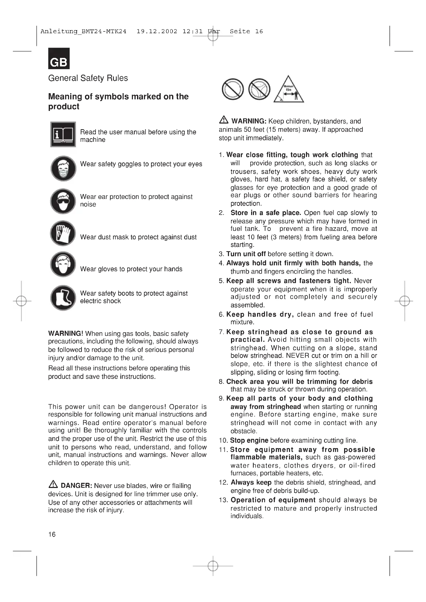
Meaning of symbols marked on the product

Read the user manual before using the machine

Wear safety goggles to protect your eyes

Wear ear protection to protect against noise

Wear dust mask to protect against dust

Wear gloves to protect your hands

Wear safety boots to protect against electric shock
WARNING! When using gas tools, basic safety precautions, including the following, should always be followed to reduce the risk of serious personal injury and/or damage to the unit.
Read all these instructions before operating this product and save these instructions.
This power unit can be dangerous! Operator is responsible for following unit manual instructions and warnings. Read entire operator's manual before using unit! Be thoroughly familiar with the controls and the proper use of the unit. Restrict the use of this unit to persons who read, understand, and follow unit, manual instructions and warnings. Never allow children to operate this unit.
DANGER: Never use blades, wire or flailing devices. Unit is designed for line trimmer use only. Use of any other accessories or attachments will increase the risk of injury.


WARNING: Keep children, bystanders, and animals 50 feet (15 meters) away. If approached stop unit immediately.
- Wear close fitting, tough work clothing that will provide protection, such as long slacks or trousers, safety work shoes, heavy duty work gloves, hard hat, a safety face shield, or safety glasses for eye protection and a good grade of ear plugs or other sound barriers for hearing protection.
- Store in a safe place. Open fuel cap slowly to release any pressure which may have formed in fuel tank. To prevent a fire hazard, move at least 10 feet (3 meters) from fueling area before starting.
- Turn unit off before setting it down.
- Always hold unit firmly with both hands, the thumb and fingers encircling the handles.
- Keep all screws and fasteners tight. Never operate your equipment when it is improperly adjusted or not completely and securely assembled.
- Keep handles dry, clean and free of fuel mixture.
- Keep stringhead as close to ground as practical. Avoid hitting small objects with stringhead. When cutting on a slope, stand below stringhead. NEVER cut or trim on a hill or slope, etc. if there is the slightest chance of slipping, sliding or losing firm footing.
- Check area you will be trimming for debris that may be struck or thrown during operation.
- Keep all parts of your body and clothing away from stringhead when starting or running engine. Before starting engine, make sure stringhead will not come in contact with any obstacle.
- Stop engine before examining cutting line.
- Store equipment away from possible flammable materials, such as gas-powered water heaters, clothes dryers, or oil-fired furnaces, portable heaters, etc.
- Always keep the debris shield, stringhead, and engine free of debris build-up.
- Operation of equipment should always be restricted to mature and properly instructed individuals.
WHAT NOT TO DO
- DO NOT USE ANY OTHER FUEL than that recommended in your manual. Always follow instructions in the Fuel and Lubrication section of this manual. Never use gasoline unless it is properly mixed with 2-cycle engine lubricant. Permanent damage to engine will result, voiding manufacturer's warranty.
- DO NOT SMOKE while refueling or operating equipment.
- DO NOT OPERATE UNIT WITHOUT A MUFFLER and properly installed muffler shield.
- DO NOT TOUCH or let your hands or body come in contact with the muffler. Hold unit with thumbs and fingers encircling the handles.
- DO NOT OPERATE UNIT IN AWKWARD POSITIONS, off balance, outstretched arms, or one-handed. Always use two hands when operating unit with thumbs and fingers encircling the handles.
- DO NOT RAISE STRINGHEAD above ground level while unit is operating. Injury to operator could result.
- DO NOT USE UNIT FOR ANY PURPOSES OTHER than trimming lawn or garden areas.
- DO NOT OPERATE UNIT FOR PROLONGED PERIODS. Rest periodically.
- DO NOT OPERATE UNIT WHILE UNDER THE INFLUENCE OF ALCOHOL OR DRUGS.
- DO NOT OPERATE UNIT UNLESS DEBRIS SHIELD AND/OR GUARD IS INSTALLED AND IN GOOD CONDITION.
- DO NOT ADD, REMOVE OR ALTER ANY COMPONENTS OF THIS PRODUCT. Doing so could cause personal injury and/or damage the unit voiding the manufacturer's warranty.
- DO NOT operate your unit near or around flammable liquids or gases whether in or out of doors. An explosion and/or fire may result.
General identification
- STRINGHEAD
2.CUTTER LINE - DEBRIS SHIELD*
4.DRIVE SHAFT ASSEMBLY - HANDLE
- THROTTLE TRIGGER
- IGNITION OFF SWITCH
- SAFETY TRIGGER
- CHOKE LEVER KNOB
- STARTER ROPE HOUSING
- FUEL TANK
- AIR FILTER COVER
- STARTER HANDLE
- MUFFLER SHIELD
- PRIMER BULB
- DEBRIS SHIELD NUT & BOLT & WASHER*
- COUPLING (MTK 24 only)
*Supplied in User Kit
NOTE: DO NOT use blades on these models.
SAFETY FEATURES
3 DEBRIS SHIELD must be installed to prevent debris from being thrown at the operator and prevent the string from extending longer than necessary.
14 MUFFLER SHIELD helps prevent hands, body and/or combustible materials from making contact with a hot muffler.
GB
Specifications
| BMT 24 MTK 24 | ||
| Engine Type Air-cooled, 2-Cycle, Chrome Cylinder Air-cooled, 2-Cycle, Chrome Cylinder | ||
| Displacement 24 cm | 3 | 24 cm3 |
| Power: 0,6 kW 0,6 kW | ||
| Dry Weight 4,5 kg 4,8 kg | ||
| Fuel Capacity 500 ml 500 ml | ||
| Drive Shaft Length 112 cm 122 cm | ||
| Cutting Width 38 cm 38 cm | ||
| Handle | Adjustable | Adjustable |
| Ignition Electronic Electronic | ||
| Drive | Centrifugal Clutch | Direct Drive |
| Nylon cutting lineø | 2,0 mm | 2,0 mm |
Assembly instructions
Handle Assembly
NOTE: The Handle is attached to the shaft but has been turned under for ease of packing.
- Loosen adjustment knob and rotate handle to top of shaft. Position handle 160mm - 220mm from throttle (Fig. 1b).
- Tighten adjustment knob securely.
- DEBRIS SHIELD (Fig. 2A - 2B)
Warning: The debris shield must be installed to properly dispense cutter line and protect operator. Shield fits snug on shaft. Some force may be required.
- Seat shield (B) onto shaft bracket (C).
- Insert washers (D) onto bolt.
- Insert bolt (E) and nut (F), tighten securely.
Drive shaft (MTK 24 only)
Installing the lower shaft
- Remove the hanger from the lower shaft (A). Press the release lever (B) while pushing the lower shaft into the tool-link coupling. (Fig. 3A)
- Locate and lock the release lever into the primary hole (C) in the shaft. (Fig. 3A)
CAUTION: Make sure the release lever is locked in the primary hole and knob is securely tightened before operating this unit.
3. Tighten the knob (D) securely clockwise before using the unit. (Fig. 3B)
CAUTION: If the incorrect hole is used, it could result in injury, or damage to the unit.
Fuel and lubrication
- Fuel
Use regular grade unleaded gasoline mixed with 2-cycle engine oil for best results. Use mixing ratios in Section FUEL MIXING TABLE.
Warning: Never use straight gasoline in your unit. This will cause permanent engine damage and void the manufacturer's warranty for that product. Never use a fuel mixture that has been stored for over 90 days.
Warning: Do not use any 2-cycle oil product with a recommended mixing ratio of 100:1. If insufficient lubrication is the cause of engine damage, it voids the manufacturer's engine warranty.
- MIXING FUEL
Mix fuel 2 cycle oil in an approved container. Use mixing table for correct ratio of fuel to oil. Shake container to ensure through mix.
Warning: Lack of lubrication voids engine warranty. Gasoline and oil must be mixed at 25:1.
- Fuel Mixing Table
Gasoline Lubricant
5 Liters 200 ml (cc)
Mixing Procedure 25 Parts Gasoline to
1 part Lubricant
1ml = 1cc
RECOMMENDED FUELS
Some conventional gasolines are being blended with oxygenates such as alcohol or an ether compound to meet clean air standards. Your engine is designed to operate satisfactorily on any gasoline intended for automotive use including oxygenated gasolines.
OPERATING INSTRUCTIONS
- STARTING A COLD ENGINE
NOTE: To minimize load on engine during starting and warm-up, trim excess cutter line to 5^ (13cm) (Fig. 5A).
- Move ignition switch to the "RUN (I)" position (Fig. 5B).
- Your unit is designed with a 3 position choke: CHOKE "F, PARTIAL " and RUN " .Move choke lever to CHOKE " F position (Fig. 5C).
- Prime the carburetor. Pump the primer bulb (A) 10 times (Fig. 5D).
- Grip handle firmly - depress safety trigger (B) & throttle trigger (C) to the FULL THROTTLE position (Fig. 5E).
- Pull starter rope out a short way until resistance is felt (approximately 100mm ) (Fig. 5F). A smooth rapid pull is required for a strong spark. Pull starter rope briskly 4 times.
- Move choke lever to PARTIAL " position (Fig. 5G).
- Pull starter rope again 4 times while trigger is in the full throttle position (Fig. 5F)
- Once engine starts, leave in the PARTIAL " position for 10 seconds.
- Move the choke to RUN " position (Fig. 5H).
- If engine fails to start, repeat steps 1 through 7.
NOTE: If engine fails to start after repeated attempts, refer to Troubleshooting section.
NOTE: Always pull starter rope straight out. Pulling starter at an angle will cause rope to rub against the eyelet. This friction will cause the rope to fray and wear more quickly. Always hold starter handle when rope retracts. Never allow rope to snap back from extended position. This could cause rope to snag or fray and also damage the starter assembly.
WARM ENGINE START
- Place trimmer on firm flat surface.
- Move ignition switch to the "RUN (I)" position (Fig. 6).
- Grip handle firmly, squeeze throttle trigger to FULL position.
- Pull starter rope briskly until engine starts, but no more than 6 times.
- If engine does not start, please operate "STARTING A COLD ENGINE" again.
TO STOP ENGINE
Release throttle trigger. Let engine return to idle. Push and hold ignition stop switch until engine stops (Fig. 6).
Trimming Instructions
- ADDITIONAL SAFETY PRECAUTIONS
Before operating your unit, review ALL SAFETY PRECAUTIONS in this manual.
WARNING / CAUTION
- IF UNFAMILIAR WITH TRIMMING techniques, practice the procedures with ENGINE in "OFF" position.
- ALWAYS CLEAR WORK area of debris such as cans, bottles, rocks, etc. Striking objects can cause serious injury to operator or bystanders and also damage equipment. If an object is accidentally hit, immediately TURN ENGINE OFF and examine equipment. Never operate unit with damaged or defective equipment.
- ALWAYS TRIM OR CUT AT HIGH ENGINE SPEEDS. Do not run engine slowly at start or during trimming operations.
DO NOT use equipment for purposes other than trimming or mowing weeds. - NEVER raise stringhead above knee height during operation.
DO NOT operate unit with other people or animals in the immediate vicinity. Allow a minimum of 50 feet (15 meters) between operator and other people and animals when trimming or mowing. Allow a distance of 100 feet (30 meters) between
GB
operator and other people and animals when SCALPING with stringhead cutter.
- IF OPERATING UNIT ON A SLOPE, stand below the cutting attachment. DO NOT OPERATE on a slope or hilly incline if there is the slightest chance of slipping or losing your footing.
STRINGHEAD LINE RELEASE
WARNING: DO NOT use steel wire or plastic-coated steel wire of any kind with your stringhead. Serious operator injury can result.
To release fresh line, run engine at full throttle and "bump" stringhead against lawn. Line will automatically release. The knife in debris shield will trim excess line (Fig. 7A).
CAUTION: Periodically remove weed wrap to prevent overheating the drive shaft. Weed wrap occurs when strands of weed become entangled around the shaft beneath the debris shield (Fig. 7B). This condition prevents the shaft from being properly cooled. Remove weed wrap with screwdriver or similar
- TRIMMING PROCEDURES
When properly equipped with a debris shield and stringhead, your unit will trim unsightly weeds and tall grass in those hard-to-reach areas - along fences, walls, foundations and around trees. It can also be used for scalping to remove vegetation down to the ground for easier preparation of a garden or to clean out a particular area.
NOTE: Even with care, trimming around foundations, brick or stone walls, curves, etc., will result in above normal string wear.
TRIMMING/MOWING
Swing trimmer with a sickle-like motion from side to side. Do not tilt the stringhead during the procedure. Test area to be trimmed for proper cutting height. Keep stringhead at same level for even depth of cut (Fig. 8A).
CLOSER TRIMMING
Position trimmer straight ahead with a slight tilt so bottom of stringhead is above ground level and string contact occurs at proper cutting point. Always cut away from operator. Do not pull trimmer in toward operator.
FENCE / FOUNDATION TRIMMING
Approach trimming around chain link fences, picket fences, rock walls and foundations slowly to cut close without whipping string against the barrier. If the string comes in contact with rock, brick walls, or foundations, it will break or fray. If string snags fencing, it will snap off.
TRIMMING AROUND TREES
Trim around tree trunks with a slow approach so string does not contact bark. Walk around the tree trimming from left to right. Approach grass or weeds with the tip of the string and tilt stringhead slightly forward.
WARNING: Use extreme caution when
SCALPING. Keep a distance of 100 feet (30 meters) between operator, other people and animals during these operations.
SCALPING
Scalping refers to removal of all vegetation down to the ground. To do this, tilt the stringhead to about a 30 degree angle to the left. By adjusting the handle you will have better control during this operation. Do not attempt this procedure if there is any chance flying debris could injure operator, other people or cause damage to property. (Fig. 8B)
EDGING FUNCTION: (MTK 24 only)
- Loosen knob (B) by turning counter clockwise (Fig. 8C).
- Push down release lever (A) and twist shaft to desired position (Fig. 8C). Edging holes positioned at 90 degrees left, 90 degrees right and 180 degrees.
- Lock lower shaft in desired edging hole with release lever.
- Tighten knob (B) securely before use by turning clockwise.
- REPLACING CUTTER LINE
- Turn knob (A) COUNTERCLOCKWISE and remove (Fig. 9A). User knob spanner supplied.
- Remove spool (B) and spring (C) from spindle (D).
- Remove any remaining cutter line (H).
- Double a 14^ (4.3m) length of .080" (2mm) cutter line. Place the looped center in one of the slots of the spool divider (Fig. 9B).
- Wind cutter line clockwise as shown in illustration (Fig. 9C), keeping tension, with each half separated by the spool divider. Wind to within 6'' (15cm) of the ends.


Fig 9A
A.KNOB
B. SPOOL
C. SPRING
D. SPINDLE
E. HOUSING
F.SLOTS
G. EYELETS
H. CUTTER LINE
- Lock each end of line (H) into a slot (F) on opposite sides of the spool (Fig. 9D).
- Install the spring (C) over the spindle (D). Insert each end of the line through an eyelet (G) in the housing (E) (Fig. 9E).
- Lower the spool into the housing (E) while feeding the line through the eyelets (G). Ensure the spring seats itself into the spool (Fig. 9E).
- Once the spool is in place, apply pressure on the spool compressing the spring. Pull each end of the line (H) sharply to unlock the line from the slots (Fig. 9F).
- Continue to apply pressure to the spool until the knob can be threaded CLOCKWISE onto the spindle. Tighten the knob securely by hand only (Fig. 9G).
- Trim the excess line to approximately 5^ (13cm). This will minimize load on engine during starting and warm-up (Fig. 5A).
·AIR FILTER
Caution: Remove fuel from unit and store in approved container before starting this procedure.
Open fuel cap slowly to release any pressure which may have formed in fuel tank.
To Clean Air Filter: (fig 11a - 11c)
- Remove 3 screws (A) holding air filter cover in place, pull out choke lever knob (B) remove cover (C) and lift filter (D) from air box.
- Wash filter in soap and water. DO NOT USE GASOLINE!
- Air dry filter.
- Reinstall filter.
NOTE: Replace filter if frayed, torn, damaged or unable to be cleaned.
FUEL CAP/FUEL FILTER
Caution: Remove fuel from unit and store in approved container before starting this procedure. Open fuel cap slowly to release any pressure which may have formed in fuel tank.
NOTE: Keep vent (A) on fuel cap clean of debris (Fig.12A).
- Lift fuel line and filter (B) out of tank. A steel wire (C) with a hook or a paper clip works well (Fig. 12B).
- Pull off with a twisting motion (Fig. 12C).
- Replace fuel filter (D).
NOTE: Never operate the trimmer without the fuel filter. Internal engine damage could result!
CARBURETOR ADJUSTMENT
The carburetor was pre-set at the factory for optimum performance. If further adjustments are necessary, please take your unit to the nearest Authorized Service Center.
SPARK PLUG
- Spark plug gap = .025" (.635mm) (Fig. 13).
- Torque to 105 to 130 inch pounds (12 to 15 N·m). Connect spark plug boot.
- DEBRIS SHIELD KNIFE SHARPENING
- Remove cutter knife (E) from debris shield (F) (Fig. 14).
- Place knife in a bench vise. Sharpen knife using a flat file, being careful to maintain the angle of cutting edge. File in one direction only.
STORING A UNIT
Warning: Failure to follow these steps may cause varnish to form in the carburetor and difficult starting or permanent damage following storage.
- Perform all the general maintenance recommended in the Maintenance Section of your User Manual.
- Clean exterior of engine, drive shaft assembly, debris shield and stringhead.
- Drain fuel from the fuel tank.
- After fuel is drained, start engine.
- Run engine at idle until unit stops. This will purge the carburetor of fuel.
- Allow engine to cool (approx. 5 minutes).
- Using a spark plug wrench, remove the spark plug.
- Pour 1 teaspoon of clean 2-cycle oil into the
GB
combustion chamber. Pull starter rope slowly several times to coat internal components. Replace spark plug.
- Store unit in a cool, dry place away from any source of ignition such as an oil burner, water heater, etc.
- REMOVING A UNIT FROM STORAGE
- Remove spark plug.
- Pull starter rope briskly to clear excess oil from combustion chamber.
- Clean and gap spark plug or install a new spark plug with proper gap.
- Prepare unit for operation.
- Fill fuel tank with proper fuel / oil mixture. See Fuel and Lubrication Section.
Trouble shooting the engine
| PROBLEM Unit won't start or starts but will not run. | PROBABLE CAUSE Incorrect starting procedures. Incorrect carburetor mixture adjustment setting. Fouled spark plug Fuel filter plugged. | CORRECTIVE ACTION Follow instructions in the User Manual. Have carburetor adjusted by an Authorized Service Center. Clean / gap or replace plug. Replace fuel filter. |
| Unit starts, but engine has low power. | Incorrect lever position on choke. Dirty air filter. Incorrect carburetor mixture adjustment setting. | Move to RUN position. Remove, clean and reinstall filter. Have carburetor adjusted by an Authorized Service Center. |
| Engine hesitates. | Incorrect carburetor mixture adjustment setting. | Have carburetor adjusted by an Authorized Service Center. |
| No power under load. Runs erratically. | Incorrectly gapped spark plug. | Clean / gap or replace plug. |
| Smokes excessively. | Incorrect carburetor mixture adjustment setting. Incorrect fuel mixture. | Have carburetor adjusted by an Authorized Service Center. Use properly mixed fuel (25:1 mixture). |
SPUSTENI MOTORU V TEPLÉM STAVU
The undersigned declares in the name of the company that the product is in compliance with the following guidelines and standards.
Eschenstraße 6 - D-94405 Landau/Isar (Germany)
The warranty period begins on the day of purchase and lasts 24 months.
The warranty covers poor workmanship or material and functional defects.
No charges will be invoiced for the replacement parts and time required by warranty claims.
Consequential damages are not covered by the warranty.
Your Customer Service Partner
GARANTIE
S.C. A Ap. 9 Sector 1
RO 75 121 Bucharest
Tel. 021 4104800, Fax 021 4103568
Cz Poker Plus S.R.O.
Areal Vu Bechovice
Budava 10B
CZ-19011 Praha - Bechovice 911
Tel.+Fax 02579 10204
Technical & Commercial company
12, Papastratou & Asklipiou Str.
GR 18545 Piräus
Tel 0210 4136155, Fax 0210 4137692
RusBermas
Altufyevskoye shosse, 2A
RUS 127372 Moscow
Tel 095 3639580,Fax 095 3639581
Technical changes subject to change
O katakevaotc diatnpei to ikaiwa TExvikw alayaw


- General Safety Rules
- Meaning of symbols marked on the product
- WHAT NOT TO DO
- General identification
- SAFETY FEATURES
- GB
- Specifications
- Assembly instructions
- Handle Assembly
- - DEBRIS SHIELD (Fig. 2A - 2B)
- Drive shaft (MTK 24 only)
- Installing the lower shaft
- Fuel and lubrication
- - Fuel
- - MIXING FUEL
- - Fuel Mixing Table
- Gasoline Lubricant
- RECOMMENDED FUELS
- OPERATING INSTRUCTIONS
- - STARTING A COLD ENGINE
- WARM ENGINE START
- TO STOP ENGINE
- Trimming Instructions
- - ADDITIONAL SAFETY PRECAUTIONS
- WARNING / CAUTION
- STRINGHEAD LINE RELEASE
- - TRIMMING PROCEDURES
- TRIMMING/MOWING
- CLOSER TRIMMING
- FENCE / FOUNDATION TRIMMING
- TRIMMING AROUND TREES
- WARNING: Use extreme caution when
- SCALPING
- EDGING FUNCTION: (MTK 24 only)
- - REPLACING CUTTER LINE
- Fig 9A
- ·AIR FILTER
- To Clean Air Filter: (fig 11a - 11c)
- FUEL CAP/FUEL FILTER
- CARBURETOR ADJUSTMENT
- SPARK PLUG
- - DEBRIS SHIELD KNIFE SHARPENING
- STORING A UNIT
- - REMOVING A UNIT FROM STORAGE
- SPUSTENI MOTORU V TEPLÉM STAVU
- GARANTIE
Brand : EINHELL
Model : BMT 24
Category : Brush cutter