
ALC100 KNX - Home automation STEINEL - Free user manual and instructions
Find the device manual for free ALC100 KNX STEINEL in PDF.

| Product Type | KNX coupler for home automation |
| Brand | Steinel |
| Model | ALC100 KNX |
| Main functions | Zone coupler, line coupler, segment coupler; line amplifier; secure proxy; galvanic isolation; KNX Data Secure; physical and group address filtering |
| Dimensions (width) | 18 mm (1 TE) |
| Weight | 90 g |
| Power supply | KNX bus DC 21–32 V SELV, current consumption upper line 9 mA, lower line 5 mA |
| Operating temperature | -5 °C to +45 °C |
| Storage temperature | -25 °C to +70 °C |
| Protection class | III |
| Mounting type | On DIN rail (IEC 60715) |
| KNX connection type | Connection terminals with polarity labeling |
| Commissioning | Via ETS (from version 5.7.7 or 6.1.1 depending on use) |
| LED indicators | RUN, MAIN, SUB, MODE, programming (red) |
| Control buttons | Programming (PROG.), Pass IA, Pass GA |
| Filtering function | Manual deactivation via Pass IA (physical address) and Pass GA (group address) buttons |
| Safety | Installation and connection reserved for a qualified electrician; compliance with SELV standards; protective caps on terminals |
| Maintenance and cleaning | No special maintenance; clean with a dry, lint-free cloth |
| Spare parts and repairability | No detachable parts; repair only by the manufacturer or an authorized service |
| Warranty | In accordance with applicable legislation (check with the reseller) |
Frequently Asked Questions - ALC100 KNX STEINEL
User questions about ALC100 KNX STEINEL
0 question about this device. Answer the ones you know or ask your own.
Ask a new question about this device
Download the instructions for your Home automation in PDF format for free! Find your manual ALC100 KNX - STEINEL and take your electronic device back in hand. On this page are published all the documents necessary for the use of your device. ALC100 KNX by STEINEL.
USER MANUAL ALC100 KNX STEINEL
Area-/Linecoupler ALC100 KNX-S
Art.-Nr. 085643
Inhaltsverzeichnis
Operating instructions
Area-/Linecoupler ALC100 KNX-S
Art.no.085643
Table of contents
1 Safety instructions 3
2 System information 3
3 Device components 3
4 Intended use 5
5 Product characteristics 5
6 Area of use 5
6.1 Backbone coupler and line coupler 5
6.2 Segment coupler and amplifier 6
7 Operation 7
8 Information for electrically skilled persons. 7
8.1 Mounting and electrical connection 7
8.2 Commissioning 8
8.2.1 Safe-state mode and master reset.. 8
9 Technical data 9
1 Safety instructions
To avoid potential damage, read and follow the following instructions:

Electrical devices may be mounted and connected only by electrically skilled persons.
Danger of electric shock. During installation and cable routing, comply with the regulations and standards which apply for SELV circuits.
This manual is an integral part of the product, and must remain with the customer.
2 System information
This device is a product of the KNX system and complies with the KNX directives. Detailed technical knowledge obtained in KNX training courses is a prerequisite to proper understanding.
The function of this device depends upon the software. Detailed information on loadable software and attainable functionality as well as the software itself can be obtained from the manufacturer's product database.
The device can be updated. Firmware can be easily updated with the STEINEL KNX Service App (additional software).
The device is KNX Data Secure capable. KNX Data Secure offers protection against manipulation in building automation and can be configured in the ETS project. Detailed technical knowledge is required. A device certificate, which is attached to the device, is required for safe commissioning. During mounting, the device certificate must be removed from the device and stored securely.
Planning, installation and commissioning of the device is carried out using ETS version 5.7.7. or higher in the case of use as a backbone coupler, line coupler or amplifier or 6.1.1 in the case of use as a backbone coupler, line coupler, segment coupler or secure proxy.
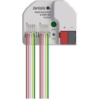
3 Device components
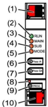
Figure 1: Front view
(1) KNX device connection terminal, subordinate line SUB
(2) Status LED RUN
(3) Status LED MAIN
(4) Status LED SUB
(5) Status LED MODE
(6) Button Pass IA
(7) Button Pass GA
(8) Programming LED, red
(9) Programming button PROG.
(10) KNX device connection terminal, higher-order line MAIN
Status LED function RUN
Off Power failure on higher-order line
Lights up green Ready for operation, higher-order and subordinate lines are supplied with voltage.
Lights up red Power failure on subordinate line.
Lights up orange Group address filter function is deactivated
Flashes orange (approx. 1 Hz) Physical address filter function is deactivated
Flashes orange quickly (approx. Both filter functions are deactivated 4 Hz)
Status LED function MAIN
Lights up orange for 6 ms Telegram reception, higher-order line
Lights up red for 6 ms One-time communication error, higher-order line
Lights up red for 100 ms Repeated communication error, higher-order line
The display of errors has a higher priority.
Status LED function SUB
Lights up orange for 6 ms Telegram reception, subordinate line
Lights up red for 6 ms One-time communication error, subordinate line
Lights up red for 100 ms Repeated communication error, subordinate line
The display of errors has a higher priority.
Status LED function MODE
Off Device functions as a backbone coupler or line coupler
Lights up green Device functions as a segment coupler or line amplifier
Lights up orange Device functions as a backbone coupler, line
coupler or segment coupler; and the secure proxy is activated
Lights up red for 100 ms Pass IA or Pass GA button has been pressed
Self-test of the status LED
During restart, the status LEDs light up green for 0.5 seconds and then red in sequence from the top to the bottom
4 Intended use
- Establishes a data link between two KNX lines/segments/backbones and ensures electrical separation between these lines/segments/backbones
- Operation as a backbone coupler, line coupler or segment coupler (from ETS 6.1.1 onwards) or amplifier (up to ETS 5.7.7)
- Installation in small distribution board on a DIN rail according to IEC 60715
5 Product characteristics
- KNX Data Secure
- Secure proxy for connection to an unencrypted and encrypted line
- Electrical separation between the higher-order and subordinate line
- Manual control used to deactivate filter functions
6 Area of use
6.1 Backbone coupler and line coupler
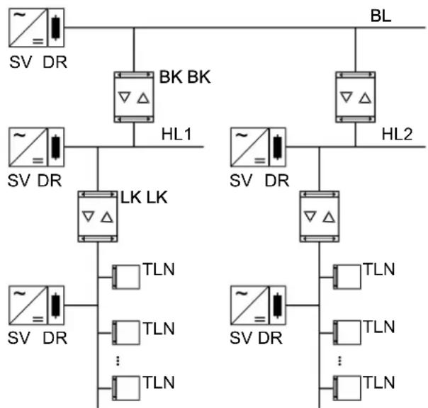
Figure 2: Use as a backbone and line coupler
Backbone coupler (BK): The physical address is the address of a backbone coupler X.0.0 and must match the logical topology of the KNX system.
Connection of a main line (HL) with a backbone line (BL). Alternatively with or without filter function. The coupler is logically assigned to the subordinate line. Observe the instructions in the technical documentation regarding the address.
Line coupler (LK): The physical address is the address of a line coupler X.Y.0 and must match the logical topology of the KNX system.
Connection of a line with a main line (HL). Alternatively with or without filter function.
The coupler is logically assigned to the subordinate line. Observe the instructions in the technical documentation regarding the address.
BK = Backbone coupler
LK = Line coupler
TLN = Bus device
SV = KNX power supply
DR = Choke
Each line segment requires a separate power supply (SV) including choke (DR).
6.2 Segment coupler and amplifier
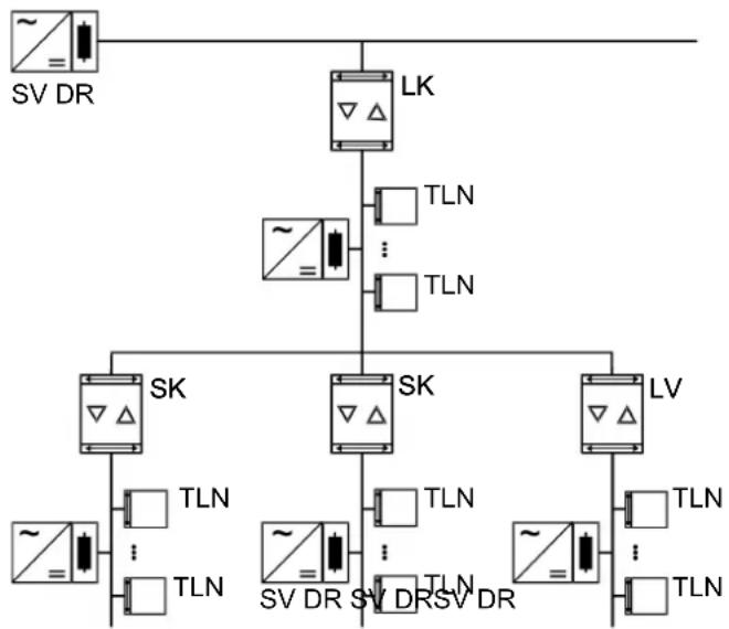
Figure 3: Use as a segment coupler and amplifier
Segment coupler (SK): The physical address is the address of a normal KNX participant X.Y.Z (Z 0) and must match the logical topology of the KNX system.
Division of a line (max. 256 participants) into independent line segments. Alternatively with or without filter function. The segment coupler is logically assigned to the subordinate line segment. Observe the instructions in the technical documentation regarding the address.
Amplifier (LV): The physical address is the address of a normal KNX participant X.Y.Z (Z 0) and must match the logical topology of the KNX system.
Division of a line (max. 256 participants) into independent line segments. Preparation and repetition of telegrams on a line, no filter function. Observe the instructions in the technical documentation regarding the address.
SK = Segment coupler
LV = Amplifier
TLN = Bus device
SV = KNX power supply
DR = Choke
Each line segment requires a separate power supply (SV) including choke (DR).
7 Operation
Deactivating the physical address filter function
Press the Pass IA button.
The status LED MODE briefly lights up red.
The status LED RUN displays the state of the filter functions, (see figure 1).
The filter is deactivated until the Pass IA button is pressed again.
Deactivating the group address filter function
Press the Pass GA button.
The status LED MODE briefly lights up red.
The status LED RUN displays the state of the filter functions, (see figure 1).
The filter is deactivated until the Pass GA button is pressed again.
8 Information for electrically skilled persons

DANGER!
Electric shock when live parts are touched.
Electric shocks can be fatal.
Cover up live parts in the installation environment.
8.1 Mounting and electrical connection
Secure operation
- Secure commissioning in the ETS is activated.
- Remove the device certificate from the device and store it securely.
-
Enter or scan the device certificate and add it to the project. Recommendation: Use a high resolution camera to scan the QR code.
-
Document all passwords and keep them safe.
Mounting and connecting the device
- Observe cable routing and spacing
- Mount device on DIN rail.
- Connect bus lines to KNX device connection terminals (see figure 1) observing the correct polarity.
- Connect the higher-order line to the lower device connection terminal (10). Power is supplied to the device via this terminal.
- Connect the subordinate line to the upper device connection terminal (1).
- Attach the cover caps to the KNX connections as protection against hazardous voltages.
The subordinate line requires a separate power supply.
8.2 Commissioning
Programming the physical address and application programme with ETS
- Switch on the bus voltage.
Press the programming button (9) PROG.. The programming LED (8) lights up. - Programming the physical address. The programming LED goes out.
■ Program the application programme and filter table.
8.2.1 Safe-state mode and master reset
Activating safe-state mode
The safe-state mode stops the execution of the loaded application program.
1 Only the system software of the device is still functional. ETS diagnosis functions and programming of the device are possible. No telegrams are transmitted.
- Switch off the bus voltage or remove the KNX device connection terminal (10) of the higher-order line.
- Press and hold down the programming button for approx. 15 seconds.
- Switch on the bus voltage or attach the KNX device connection terminal. Release the programming button only after the programming LED starts flashing slowly.
The safe-state mode is activated.
By briefly pressing the programming button again, the programming mode can also be switched on and off in the safe-state mode. If the programming mode is active, the programming LED stops flashing.
Deactivating safe-state mode
- Switch off the bus voltage for approx. 15 seconds or trigger a restart via the ETS.
Master reset
The master reset restores the basic device settings (physical address 15.15.0, firmware remains in place). The device must then be recommissioned with the ETS.
In secure operation: A master reset deactivates device security. The device can then be recommissioned with the device certificate.
Performing a master reset
Precondition: The safe-state mode is activated.
- Press and hold down the programming button for >5 s. The programming LED flashes quickly.
- Release the programming button.
The device performs a master reset, restarts and is ready for operation again after approx. 5 s.
Restoring the device to factory settings
The device can be reset to factory settings with the STEINEL KNX Service App. This function uses the firmware contained in the device that was active at the time of delivery (delivered state). Restoring the factory settings causes the device to lose its physical address and configuration.
9 Technical data
Ambient temperature -5 ... +45°C
Storage/transport temperature -25 ... +70°C
Protection class III
Weight 90 g
Installation width 18 mm / 1 HP
KNX medium TP256
Commissioning mode S mode
Rated voltage KNX DC 21 ... 32 V SELV
Current consumption, KNX
Higher-order line 9 mA
Subordinate line 5 mA
Connection mode KNX Device connection terminal
STEINEL GmbH
Dieselstraße 80-84
33442 Herzebrock-Clarholz
Telefon +49 5245 448 0
www.steinel.de
product@steinel.de
Area-/Linecoupler ALC100 KNX-S
Núm. de art. 085643
Indices
Tension nominal KNX DC 21 ... 32 V MBTS
Consumo de corriente KNX
Linea principal 9 mA
Linea secundaria 5mA
Area-/Linecoupler ALC100 KNX-S
Ref. 085643
Sommaire
TLN = participant de bus
SV = tension d'alimentation KNX
DR = réactance
TLN = participant de bus
SV = tension d'alimentation KNX
DR = reactance
Désactiver le mode Safe State
Area-/Linecoupler ALC100 KNX-S
N. art. 085643
Indice
8.2.1 Safe State Mode Master reset
Area-/Linecoupler ALC100 KNX-S
Art.nr.085643
Inhoudsopgave
Nominate spanning KNX DC 21 ... 32 V SELV
Area-/Linecoupler ALC100 KNX-S
Art.-nr. 085643
Selvtest for status-LED
Ved omstart lyser status-LED-ene gront i 0,5 sekunder og deretter rødt fra topp til cunning
SV = KNX-spenningsforsyning
DR = Induktans
En separat spenningsforsyning (SV) inkludert induktans (DR) er nødvendig for hvert linjesegment.
Utfore Master-omstart
Forutsetting: Safe-State-modus er aktivert.
Trykk pa programmeringstasten, og hold den >5 s.
Programmerings-LED-en blinker raskt.
Slipp programmingstasten.

- Inhaltsverzeichnis
- Operating instructions
- Table of contents
- Safety instructions
- System information
- Device components
- Status LED function RUN
- Status LED function MAIN
- Status LED function SUB
- Status LED function MODE
- Self-test of the status LED
- Intended use
- Product characteristics
- Area of use
- Backbone coupler and line coupler
- Segment coupler and amplifier
- Operation
- Information for electrically skilled persons
- DANGER!
- Mounting and electrical connection
- Secure operation
- Commissioning
- Safe-state mode and master reset
- Technical data
- Indices
- Sommaire
- Désactiver le mode Safe State
- Indice
- Safe State Mode Master reset
- Inhoudsopgave
- Selvtest for status-LED
Brand : STEINEL
Model : ALC100 KNX
Category : Home automation