UI4 KNX - Home automation STEINEL - Free user manual and instructions
Find the device manual for free UI4 KNX STEINEL in PDF.

| Product Type | KNX input/output interface |
| Brand | Steinel |
| Model | UI4 KNX |
| Number of channels | 2, 4 or 8 depending on variant |
| Power supply | KNX bus (DC 21…32 V) |
| KNX consumption | 5…18 mA depending on number of channels |
| Ambient temperature | -5…+45 °C |
| Storage temperature | -25…+75 °C |
| Protection | IP20, class III |
| Dimensions (L×W×H) 2/4 channels | 43.0 × 28.5 × 15.4 mm |
| Dimensions (L×W×H) 8 channels | 43.5 × 35.5 × 15.4 mm |
| Number of inputs | Up to 8 (potential-free contacts) |
| Number of outputs | Up to 8 (for LEDs) |
| Output voltage | 5 V DC SELV |
| Output current per channel | 3.2 mA max. |
| Connection cable length | 25 cm, extendable up to 30 m |
| Input functions | Switching, dimming, blind, scene, temperature, pulse counter, logic |
| Output functions | LED control, short-circuit/overload/reverse polarity protection |
| KNX compatibility | TP256, Mode S, ETS ≥5.7.7 or 6.1.0 |
| Security | KNX Data Secure, device certificate |
| Warranty | In accordance with legislation |
Frequently Asked Questions - UI4 KNX STEINEL
User questions about UI4 KNX STEINEL
0 question about this device. Answer the ones you know or ask your own.
Ask a new question about this device
Download the instructions for your Home automation in PDF format for free! Find your manual UI4 KNX - STEINEL and take your electronic device back in hand. On this page are published all the documents necessary for the use of your device. UI4 KNX by STEINEL.
USER MANUAL UI4 KNX STEINEL
(1) (2) (3) (4)
Operating instructions
Universal Input UI2 KNX-S
Art. no. 089221
Universal Input UI4 KNX-S
Art. no. 089238
Universal Input UI8 KNX-S
Art. no. 089245
Table of contents
1 Safety instructions .... 3
2 System information.... 3
3 Intended use.... 3
4 Product characteristics .... 4
5 Mounting and electrical connection 4
6 Commissioning 8
6.1 Safe-state mode and master reset.... 8
7 Technical data 9
8 Warranty 10
1 Safety instructions
To avoid potential damage, read and follow the following instructions:

Electrical devices may be mounted and connected only by electrically skilled persons.
Danger of electric shock. During installation and cable routing, comply with the regulations and standards which apply for SELV circuits.
Danger of electric shock. Make sure during the installation that there is always sufficient insulation between the mains voltage and the bus. A minimum distance of at least 4 mm must be maintained between bus conductors and mains voltage cores.
Danger of electric shock on the installation. Do not connect any external voltage to the inputs. The device might be damaged, and the SELV potential on the bus line will no longer be available.
This manual is an integral part of the product, and must remain with the customer.
2 System information
This device is a product of the KNX system and complies with the KNX directives. Detailed technical knowledge obtained in KNX training courses is a prerequisite to proper understanding.
The function of this device depends upon the software. Detailed information on loadable software and attainable functionality as well as the software itself can be obtained from the manufacturer's product database.
The device can be updated. Firmware can be easily updated with the STEINEL KNX Service App (additional software).
The device is KNX Data Secure capable. KNX Data Secure offers protection against manipulation in building automation and can be configured in the ETS project. Detailed technical knowledge is required. A device certificate, which is attached to the device, is required for safe commissioning. During mounting, the device certificate must be removed from the device and stored securely.
Planning, installation and commissioning of the device are carried out with the aid of the ETS, version 5.7.7 and higher or 6.1.0.
3 Intended use
- Outputs for polling of conventional, potential-free contacts in KNX systems and for sending telegrams to the KNX bus for reporting of states, meter levels, operation of loads, etc.
– Outputs for activation of LEDs - Mounting in appliance box with dimensions according to DIN 49073 in combination with a suitable cover
- When mounting behind switch inserts and push-button inserts, use an appliance box with sufficient installation depth
4 Product characteristics
- Depending on the variant, two, four or eight independent channels, which work as inputs or as outputs, depending on the ETS configuration
– Common reference potential for all channels
– Disabling of individual channels
– Supply via the KNX bus, no additional supply voltage necessary
Inputs
- Connection of potential-free contacts such as push-buttons, switches or Reed contacts
- Impulse current for avoiding contact fouling (image of an oxide layer) at the connected contacts
- Operating functions: switching, dimming, controlling of Venetian blinds, moods or room temperature
– Value transmitter for dimming, colour temperature, RGBW, temperature and brightness values - Transmission of the current input state after bus voltage failure
- Connection of door or window contacts for the evaluation of the status open, closed, tilted and grip position
- Connection of leakage, condensation and temperature sensors (on request)
– Pulse counter with main counter and intermediate counter - Combination of adjacent input channels for connection of push-button, door contact and window contact
- Logic functions
Outputs
- Connection of LEDs
– Short-circuit resistant, overload-protected and reverse-polarity protected - Switching outputs in parallel possible, for loads with higher energy consumption
5 Mounting and electrical connection
Mount device
In secure operation (preconditions):
- Secure commissioning is activated in the ETS.
– Device certificate entered/scanned or added to the ETS project. A high resolution camera should be used to scan the QR code. - Document all passwords and keep them safe.
■ In secure operation: device certificate must be removed from the device and stored securely.
■ Mounting in suitable appliance box. Observe cable routing and spacing.
Bus connection
■ Connect bus with a KNX device connection terminal to KNX connection (1) (see figure 1).
(1) (2) (3) (4)
(1) (2)(3) (4)
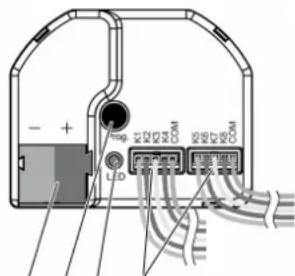
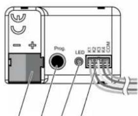
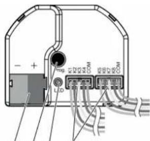
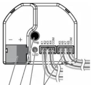
Figure 1: Device components
(1) KNX connection
(2) Programming button
(3) Programming LED
(4) Connection cables
Installation instructions
- To avoid interference from EMC radiation, the cables of the inputs should not run parallel to cables carrying mains voltage or to load cables.
- The voltage potentials of the connecting cables for the inputs and outputs are not galvanically isolated from the bus voltage.
The connecting cables actually lengthen the bus cable. The specification for the bus cable length (max. 1000 m) must be observed.
- Do not connect the COM connections of multiple push-button interfaces.
- No series resistance required for the connection of LEDs.
- Use channels 1 and 2 for NTC temperature sensors. Select a compatible NTC temperature sensor based on the characteristic curve of the NTC (see tables below).
Characteristic curve of the NTC
| R_25^ | 33 kΩ |
| B_25/100 | 4300 K |
| T [°C] R | _T/R_25 | α [%/K] R | _T [kΩ, rounded] |
| -30.0 | 21.56700 6.6 711.7 | ||
| -10.0 | 6.29270 5.9 207.7 | ||
| -5.0 | 4.70770 5.7 155.4 | ||
| 0.0 | 3.55630 5.5 117.4 | ||
| 5.0 | 2.71190 5.3 89.5 | ||
| 10.0 | 2.08600 5.1 68.8 | ||
| 15.0 | 1.62040 5.0 53.5 | ||
| 20.0 | 1.26830 4.8 41.9 | ||
| 25.0 | 1.00000 4.7 33.0 | ||
| 30.0 | 0.79420 4.6 26.2 | ||
| 35.0 | 0.63268 4.5 20.9 | ||
| 40.0 | 0.50740 4.3 18.9 | ||
| 45.0 | 0.41026 4.2 13.5 | ||
| 50.0 | 0.33363 4.1 11.0 | ||
| 55.0 | 0.27243 4.0 9.0 | ||
| 60.0 | 0.22370 3.9 7.4 | ||
| 70.0 | 0.15305 3.7 5.1 | ||
| 80.0 | 0.10677 3.5 3.5 | ||
| 90.0 | 0.07607 3.3 2.5 |
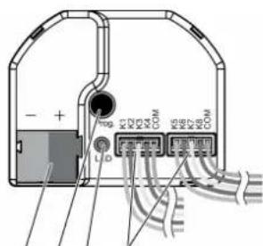
For the extension of the enclosed cable set (see figure 2), observe the maximum cable length. The com cable for each cable set may not have a total length beyond 30 m in length.
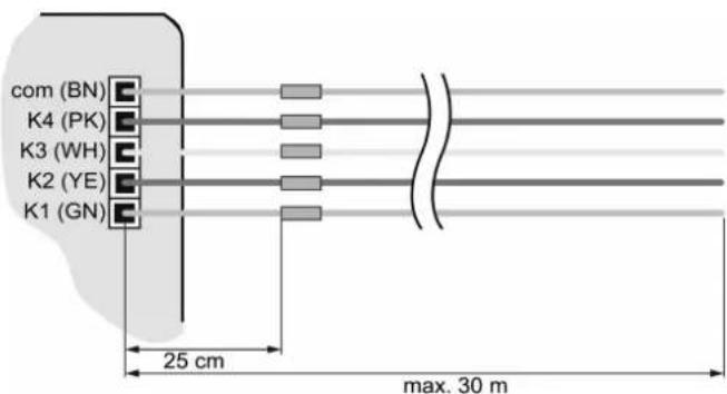
Figure 2: Maximum cable length
Connect device

DANGER!
Danger of electrical shock when mains voltage 230 V or other external voltages are connected!
Electric shocks can be fatal.
Device may be destroyed.
Only connect potential-free push-buttons, switches or contacts.
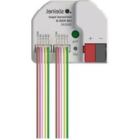
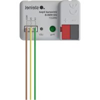
■ Connect push-buttons, switches, contacts, LED or NTC to enclosed connecting cables (4) according to the connection examples; (see figure 3) to (see figure 6). The connection examples show the use with inputs and outputs.
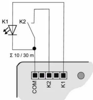
Figure 3: Connection example: push-button interface 2-gang
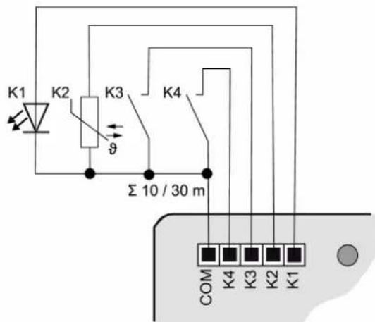
Figure 4: Connection example: push-button interface 4-gang
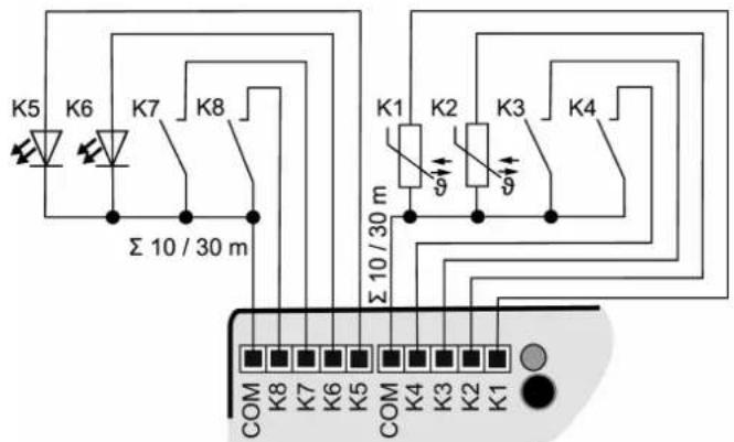
Figure 5: Connection example: push-button interface 8-gang
To increase the output current, outputs can also be switched parallel to each other with the same parameterization; in the example here, (see figure 6) K1-K3 are switched in parallel.
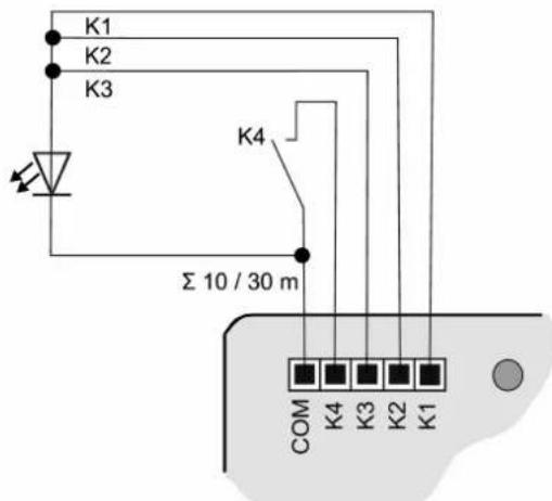
Figure 6: Connection example with outputs switched in parallel
6 Commissioning
Programming the physical address and application program
■ Switch on the bus voltage.
■ Press the programming button (2).
The programming LED (3) lights up.
■ Program the physical address with the ETS. The programming LED goes out.
■ Program the application program with the ETS.
6.1 Safe-state mode and master reset
Safe-state mode
The safe-state mode stops the execution of the loaded application program.
Only the system software of the device is still functional. ETS diagnosis functions and programming of the device are possible.
Activating safe-state mode
■ Switch off the bus voltage or remove the KNX device connection terminal
■ Wait approx. 10 seconds.
■ Press and hold down the programming button.
■ Switch on the bus voltage or attach the KNX device connection terminal.
■ Wait until the programming LED flashes slowly.
■ Release the programming button.
The safe-state mode is activated.
By briefly pressing the programming button again, the programming mode can also be switched on and off in the safe-state mode as usual. If the programming mode is active, the programming LED stops flashing.
Deactivating safe-state mode
■ Switch off bus voltage (wait approx. 10 seconds) or carry out ETS programming.
Master reset
The master reset restores the basic device settings (physical address 15.15.255, firmware remains in place). The device must then be recommissioned with the ETS.
In secure operation: A master reset deactivates device security. The device can then be recommissioned with the device certificate.
Performing a master reset
Precondition: The safe-state mode is activated.
■ Press and hold down the programming button for > 5 s.
The programming LED flashes quickly.
■ Release the programming button.
The device performs a master reset, restarts and is ready for operation again after approx. 5 s.
Restoring the device to factory settings
The device can be reset to factory settings with the STEINEL KNX Service App. This function uses the firmware contained in the device that was active at the time of delivery (delivered state). Restoring the factory settings causes the device to lose its physical address and configuration.
7 Technical data
Ambient temperature -5 ... +45°C
Storage/transport temperature -25 ... +75°C
Degree of protection IP20
Protection class III
Number of channels
089221 2
089238 4
089245 8
Output voltage DC 5 V SELV
Output current per channel max. 3.2 mA
LED current (red LED with 1.7 V current voltage) 2.2 mA per output
Connection of channels
089221 3-core wiring harness
089238 5-core wiring harness
089245 2x 5-core wiring harness
Length, wiring harness 25 cm, can be extended to max. 30 m
Recommended cable J-Y(St)Y 2×2×0.8
Dimensions (LxWxH)
089221, 089238 43.0 x 28.5 x 15.4 mm
089245 43.5 x 35.5 x 15.4 mm
KNX medium TP256
Commissioning mode S mode
Rated voltage KNX DC 21 ... 32 V SELV
Current consumption, KNX
089221 5 ... 10 mA
089238 5 ... 12 mA
089245 5 ... 18 mA
Connection mode KNX Device connection terminal
8 Warranty
We reserve the right to make technical and formal changes to the product in the interest of technical progress.
We provide a warranty as provided for by law.
STEINEL GmbH
Dieselstraße 80-84
33442 Herzebrock-Clarholz
Telefon +49 5245 448 0
www.steinel.de
product@steinel.de
(1) (2) (3) (4)
(1) (2)(3) (4)
Figura 1: Estructura del aparato
Activer le mode Safe State
Désactiver le mode Safe State
6.1 Safe State Mode e Master reset
Modalità Safe State
(1) (2) (3) (4)
Bilde 2: Maksimal ledningslengde
Koble til apparatet